EP1155914A2 - Fahrzeug- Dachrelingbefestigungsvorrichtung - Google Patents
Fahrzeug- Dachrelingbefestigungsvorrichtung Download PDFInfo
- Publication number
- EP1155914A2 EP1155914A2 EP01112134A EP01112134A EP1155914A2 EP 1155914 A2 EP1155914 A2 EP 1155914A2 EP 01112134 A EP01112134 A EP 01112134A EP 01112134 A EP01112134 A EP 01112134A EP 1155914 A2 EP1155914 A2 EP 1155914A2
- Authority
- EP
- European Patent Office
- Prior art keywords
- roof
- railing
- channel
- molding
- piping
- Prior art date
- Legal status (The legal status is an assumption and is not a legal conclusion. Google has not performed a legal analysis and makes no representation as to the accuracy of the status listed.)
- Granted
Links
Images


Classifications
-
- B—PERFORMING OPERATIONS; TRANSPORTING
- B60—VEHICLES IN GENERAL
- B60R—VEHICLES, VEHICLE FITTINGS, OR VEHICLE PARTS, NOT OTHERWISE PROVIDED FOR
- B60R9/00—Supplementary fittings on vehicle exterior for carrying loads, e.g. luggage, sports gear or the like
- B60R9/04—Carriers associated with vehicle roof
Definitions
- the present invention relates to a fastening device for a railing a roof channel of motor vehicle roofs, with a plurality of fastening means for fastening the railing at several points and one piece Roof molding to cover the roof duct.
- Such a fastening device is known from DE 36 26 926 C2.
- Such rail arrangements are characterized in that the roof rail is in one piece and extends over the entire length of the roof channel to be covered extends.
- the attachment of the railing must be designed to be massive intercept the high forces that occur with large roof loads on the railing.
- the roof molding is provided for this by means of several Bolt solidly to the body in the roof channel area.
- the railing itself is integrally formed in one piece on the roof molding or also by means of a variety of screws attached to this to provide the necessary strength of the To achieve connection.
- this known device is in several respects room for improvement. So it is e.g. unsatisfactory due to the massive construction regarding the weight of the railing. In addition, the manufacturing this rail fastening relatively expensive.
- the present invention is therefore based on the object of an improved To create device of the type mentioned, which the state of the art in advantageously further training.
- the integral length of the roof duct to be covered thus has recesses through which the railing can be attached the fastener is anchored to a wall of the roof channel.
- the railing is not screwed or molded onto the roof molding, but directly attached to the roof channel itself.
- the forces acting on the railing become by the extension of the fasteners through the roof molding not in the latter initiated, the anchorage of the railing is provided separately from the roof molding.
- no massive attachment of the roof molding is required be, the roof molding itself can be thin and lightweight. As a result, considerable weight savings can be achieved.
- the attachment of the roof molding itself can be done in different ways.
- the Roof molding can be attached to the railing at the same time as the railing Roof channel be fixed.
- the fastening of the roof molding is preferred decoupled from the fasteners for the railing and are from the fasteners separate fasteners for the roof rail are provided for the railing, with which this can be attached to the roof channel.
- the fasteners can be designed differently for the roof molding.
- the roof molding can be clamped non-positively. According to a preferred embodiment of the Invention, the roof molding is locked in a form-fitting manner.
- a piping is provided in the roof channel under the roof molding to which the roof molding is attached.
- the roof molding and / or the piping can Have locking tongues, by means of which the roof molding by pressing on the piping can be locked.
- the piping is preferably formed in several pieces, so that the railing is immediate can be anchored to the roof channel.
- the piping can also if necessary have corresponding recesses in the area of the fastening means for the railing, through which the fastening means for the railing on the wall of the roof channel can be attached.
- the roof molding is advantageous Can be pre-assembled independently of the railing, the railing is separate from the roof molding removable.
- the railing is anchored in the roof channel by means of latching brackets Support the rail at the bottom of the roof channel so that it cannot tilt.
- the tensile force of the fasteners is placed on the floor of the roof channel via the latching blocks.
- the Latching blocks can in principle be integrally formed on the railing.
- the latching blocks are formed separately from the railing and are made by the Fasteners clamped between the roof channel and the railing.
- the latching blocks can lie with a support surface under the roof rail, so that they also support the roof molding.
- the latching blocks preferably pass through the Cutouts in the roof molding and have a height that is greater than the distance of the top of the top of the roof molding from the bottom of the roof duct. You can easily with their support surface against which the railing is clamped project over the roof molding. This ensures that the railing is not is tensioned against the roof rail and on the railing holding forces on the Roof ledge can be initiated.
- the latching blocks and the Roof molding not each other.
- the recesses in the roof rail are preferably larger than that Cross section of the locking blocks passing through them, so that the locking blocks with Play in the recesses and manufacturing tolerances are compensated can.
- the latching blocks have passage recesses through which the Fasteners for the railing can pass through.
- fasteners are preferably provided screw connections, on the one hand with the railing and on the other hand, can be connected to the floor of the roof duct. This allows the Railing solid against the floor of the roof channel or against the corresponding one Support surface of the latching blocks can be tensioned.
- Corresponding in the roof channel floor Holes are provided, inserted through the bolts and can be screwed with nuts.
- the piping to which the roof molding is attached is, preferably have integrally molded keder lips, which have a positive fit between the roof molding and the roof channel. Center through this the piping lips the roof molding. They can also provide a backup for the Form the roof molding against unintentional loosening. You can go to the section of Attack the roof rail, which is locked with the piping, so that the locking between Roof molding and piping is secured.
- the piping can be integrally formed in one piece from different materials.
- a central piping body to which the roof rail is attached is advantageous is made of a harder material than the keder lips. This results in a best possible adaptation of the piping sections to their respective function.
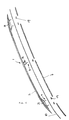
- the railing 1 shown in FIG. 1 comprises a railing rail 2, which is attached to its two End and supported approximately in the middle by a railing column 3 becomes.
- the railing columns 3 are directly in the ground by means of screw connections 4 of a roof channel 5 anchored in the edge region of a motor vehicle roof is provided.
- the roof channel 5, which is essentially rectangular in cross section, is as shown in Figures 3 and 5, limited by roof and side panels, which in Bottom area of the roof channel 5 are welded together.
- the bottom 6 of the Roof channel 5 is essentially flat.
- a piping 7 is used, which is formed in several pieces. How Fig. 1 shows, the piping 7 comprises several parts that are between the screw connections 4 of the rail 1 extend in the roof channel 5. In the field of screw connections 4 no piping is provided in the roof channel 5.
- the piping comprises a central piping body 8 (see FIG. 5), which is at the bottom 6 of the Roof channel 5 stands up and on its facing towards the light side of the roof channel 5 End positive and non-positive fasteners Attachment of the roof molding 10 has.
- the piping 7 has on its the bottom 6 of the roof channel 5 facing away from the end two to the side walls of the roof channel 5 projecting locking tongues 9, each of which is a web-shaped Extend projection in the longitudinal direction of the welt 7 and the roof channel 5. Between the locking tongues 9, the piping 7 has a spring recess 11, the one Compression of the locking tongues 9 allowed to each other.
- the roof molding 10 which has a substantially U-shaped cross section, has on its parallel legs 12 inwardly projecting locking tongues 13, which are complementary to the locking tongues 9 of the welt 7.
- the roof molding 10 can be attached to the piping 7 by being pressed onto it is so that the locking tongues 9 of the piping with the locking tongues 13 of the roof molding 10 engage and lock the roof molding 10 on the piping 7 (see Fig. 5).
- the width of the roof molding 10 is narrower than the width of the roof channel 5, so that between the legs 12 of the roof molding 10 and the side walls of the Roof channel 5 is a gap.
- the piping has a second pair of piping lips 16 which extend from the central one Keder body 8 below the first keder lips 15, i.e. closer to the ground 6 of the roof channel 5, essentially from a foot region of the central welt body 8 project from the side. They also nestle against the side walls of the roof channel 5 and seal this towards the floor (see FIG. 5).
- the roof channel 5 has an undercut 17 in which one of the second keder lips is located 16 spread, so that the piping 7 is held in the roof channel 5.
- the piping 7 includes its central body 8 and the piping lips 15 and 16 integrally molded in one piece, in particular it can consist of polyvinyl chloride.
- the piping lips have a lower hardness than the piping body.
- each screw connection has 4 locking blocks 19 assigned, which on the one hand rest on the flat floor 6 of the roof channel 5 and have at their opposite end support surfaces 20 on which the Railing columns 3 can rest.
- the Latching blocks 19 through the roof molding 10, i.e. their height is greater than that Distance of the top of the roof molding 10 from the bottom 6 of the roof duct 5.
- the support surface 20 of the latching blocks 19 is above in the embodiment shown the top of the roof molding 10.
- the latching blocks 19 have a central passage recess 21 through which through which the screw connection 4 extends.
- the passage recess 21 extends centrally and the support surfaces of the latching bracket 19 extend around the passage recess around, so that the respective latching frame is full and is pulled stable against the bottom of the roof channel recess 5.
- the Through recess 21 widens in the longitudinal direction of the roof channel 5 Bottom side of the same in its cross section (see. Fig. 4), while transverse to Longitudinal direction of the roof channel straight flanks, i.e. a consistent one Cross section has (see Fig. 3).
- the recess 18 in the roof molding 10 is larger than the cross section of the respective locking bracket 19, so that the locking bracket 19 with Game can pass through the recess 18. This will cause tension or a force transmission to the roof molding 10 avoided.
- each screw connection 4 passes through the base 6 of the roof channel 5 through. It can be screwed with a corresponding nut or possibly also in a screw sleeve assigned to the bottom be screwed in. This ensures that all forces be directed into the floor of the roof channel.
Landscapes
- Engineering & Computer Science (AREA)
- Mechanical Engineering (AREA)
- Body Structure For Vehicles (AREA)
- Fittings On The Vehicle Exterior For Carrying Loads, And Devices For Holding Or Mounting Articles (AREA)
Abstract
Description
- Fig. 1
- eine perspektivische Ansicht des Relingverbaus gemäß einer bevorzugten Ausführung der Erfindung in einer Explosionsdarstellung, die die Reling, die Dachleiste, den Keder und Rastböcke für die Befestigung der Reling zeigt,
- Fig. 2
- eine ausschnittsweise Darstellung der Befestigung einer rückwärtigen Relingsäule der Reling aus Fig. 1 in montiertem Zustand,
- Fig. 3
- eine Schnittansicht quer zur Längsrichtung des Dachkanales einer Schraubverbindung zwischen Reling und Dachkanalboden mit einem Rastbock durch die Dachleiste hindurch gemäß einer bevorzugten Ausführung der Erfindung,
- Fig. 4
- eine Schnittansicht der Schraubverbindung aus Fig. 3 in Längsrichtung des Dachkanals, und
- Fig. 5
- eine Schnittansicht quer zur Längsrichtung des Dachkanals, des darin angeordneten Keders und der daran befestigten Dachleiste gemäß einer bevorzugten Ausführung der Erfindung, wobei Kederlippen in ihrer unmontierten, entspannten Stellung gezeichnet sind.
Claims (7)
- Befestigungsvorrichtung für eine Reling an einem Dachkanal von Kraftfahrzeugdächern, mit einer Mehrzahl von Befestigungsmitteln zur Befestigung der Reling an mehreren Punkten sowie einer einstückigen Dachleiste zur Abdekkung des Dachkanales, dadurch gekennzeichnet, daß die Dachleiste (10) Aussparungen (18) aufweist, durch die hindurch die Reling (1) mittels der Befestigungsmittel (4) an einer Wandung (6) des Dachkanals (5) verankert ist.
- Vorrichtung nach dem vorhergehenden Anspruch, wobei die Dachleiste (10) mittels eigener Befestigungsmittel (9, 13) an dem Dachkanal (5) befestigt ist, insbesondere in dem Dachkanal (5) unter der Dachleiste (10) ein Keder (7) vorgesehen ist, an dem die Dachleiste (10) befestigt, vorzugsweise formschlüssig verrastet ist.
- Vorrichtung nach einem der vorhergehenden Ansprüche, wobei Rastböcke (19) zur Abstützung der Reling (1) jeweils im Bereich der Aussparungen (18) der Dachleiste (10) vorgesehen sind, vorzugsweise am Boden (6) des Dachkanals (5) aufliegen und durch die Aussparungen (18) in der Dachleiste (10) hindurchtreten.
- Vorrichtung nach dem vorhergehenden Anspruch, wobei die Rastböcke (19) Durchgangsausnehmungen (21) zum Durchtritt der Befestigungsmittel (4) aufweisen.
- Vorrichtung nach einem der vorhergehenden Ansprüche, wobei als Befestigungsmittel Schraubverbindungen (4) vorgesehen sind, die einerseits mit der Reling (1) und andererseits mit dem Boden (6) des Dachkanals (5) verbindbar sind.
- Vorrichtung nach einem der vorhergehenden Ansprüche, wobei zwischen die Dachleiste (10) und den Dachkanal (5) eine Spaltabdeckung geschaltet ist, vorzugsweise Kederlippen (15) formschlüssig dazwischengefügt sind.
- Vorrichtung nach einem der vorhergehenden Ansprüche, wobei im Bereich der Aussparungen (18) der Dachleiste (10) die Reling (1) den Dachkanal (5) überdeckt.
Applications Claiming Priority (4)
| Application Number | Priority Date | Filing Date | Title |
|---|---|---|---|
| DE10024245 | 2000-05-17 | ||
| DE10024245 | 2000-05-17 | ||
| DE10038123A DE10038123A1 (de) | 2000-05-17 | 2000-08-04 | Befestigungsvorrichtung |
| DE10038123 | 2000-08-04 |
Publications (3)
| Publication Number | Publication Date |
|---|---|
| EP1155914A2 true EP1155914A2 (de) | 2001-11-21 |
| EP1155914A3 EP1155914A3 (de) | 2003-08-06 |
| EP1155914B1 EP1155914B1 (de) | 2005-08-03 |
Family
ID=26005719
Family Applications (1)
| Application Number | Title | Priority Date | Filing Date |
|---|---|---|---|
| EP20010112134 Expired - Lifetime EP1155914B1 (de) | 2000-05-17 | 2001-05-17 | Fahrzeug- Dachrelingbefestigungsvorrichtung |
Country Status (2)
| Country | Link |
|---|---|
| EP (1) | EP1155914B1 (de) |
| ES (1) | ES2246959T3 (de) |
Cited By (1)
| Publication number | Priority date | Publication date | Assignee | Title |
|---|---|---|---|---|
| CN116409248A (zh) * | 2021-12-31 | 2023-07-11 | 广东东箭汽车科技股份有限公司 | 连接组件及车体组件 |
Citations (1)
| Publication number | Priority date | Publication date | Assignee | Title |
|---|---|---|---|---|
| DE3626926C2 (de) | 1986-08-08 | 1988-07-21 | Daimler-Benz Ag, 7000 Stuttgart, De |
Family Cites Families (6)
| Publication number | Priority date | Publication date | Assignee | Title |
|---|---|---|---|---|
| DE3153106C2 (de) * | 1981-12-24 | 1986-10-02 | Adam Opel AG, 6090 Rüsselsheim | Blendleiste |
| FR2657055A1 (fr) * | 1990-01-16 | 1991-07-19 | Peugeot | Baguette d'enjoliveur et systeme porte-bagages pour vehicule automobile. |
| FR2687964B1 (fr) * | 1992-03-02 | 1997-06-13 | Profil | Enjoliveur de pavillon de vehicule automobile. |
| DE4237158C2 (de) * | 1992-11-04 | 1998-01-08 | Schade Gmbh & Co Kg | Abdeckleiste für eine in ein Fahrzeugdach eingelassene Rinne |
| DE19732288A1 (de) * | 1997-07-26 | 1999-02-11 | Bayerische Motoren Werke Ag | Verfahren zum Herstellen eines Dachgepäckträgers, insbesondere einer Reling |
| ES2151411B1 (es) * | 1998-08-07 | 2001-06-01 | Ind Ilpea Espana S A | Junta para recubrimiento de uniones soldadas en carrocerias de automoviles. |
-
2001
- 2001-05-17 EP EP20010112134 patent/EP1155914B1/de not_active Expired - Lifetime
- 2001-05-17 ES ES01112134T patent/ES2246959T3/es not_active Expired - Lifetime
Patent Citations (1)
| Publication number | Priority date | Publication date | Assignee | Title |
|---|---|---|---|---|
| DE3626926C2 (de) | 1986-08-08 | 1988-07-21 | Daimler-Benz Ag, 7000 Stuttgart, De |
Cited By (1)
| Publication number | Priority date | Publication date | Assignee | Title |
|---|---|---|---|---|
| CN116409248A (zh) * | 2021-12-31 | 2023-07-11 | 广东东箭汽车科技股份有限公司 | 连接组件及车体组件 |
Also Published As
| Publication number | Publication date |
|---|---|
| EP1155914A3 (de) | 2003-08-06 |
| EP1155914B1 (de) | 2005-08-03 |
| ES2246959T3 (es) | 2006-03-01 |
Similar Documents
| Publication | Publication Date | Title |
|---|---|---|
| DE3417337C2 (de) | Anordnung eines Kraftfahrzeug-Frontteils aus Kunststoff an der Fahrzeugkarosserie | |
| EP2804786B1 (de) | Dachreling für ein kraftfahrzeug | |
| DE102018108149B3 (de) | Dekor-Zierblende an einer Kfz-Felge | |
| EP2878743B1 (de) | Anordnung zur Ausbildung eines Bodenbelags | |
| EP3614885A1 (de) | Rahmenkonstruktion für ein regalsystem | |
| DE2931026A1 (de) | Anordnung zur erstellung von wand- und/oder deckenkonstruktionen, insbesondere im messebau | |
| DE10035802C2 (de) | Vorrichtung zur Befestigung einer aufrollbaren Markise auf dem Dach eines Wohnwagens, Wohnmobils oder dergleichen | |
| DE102009007120A1 (de) | Befestigungselement für ein Verlegesystem zur Erstellung eines Wand-, Boden- oder Deckenbelages sowie ein solches Verlegesystem | |
| EP1393653B1 (de) | Mehrteilige Seitenzarge für einen Schubkasten | |
| DE10065962A1 (de) | Metallprofil für Strassenmöbelkonstruktionen | |
| DE202019101409U1 (de) | Profilsystem zur Bildung eines Untertragrahmens für die Aufnahme von Bodenbelägen und Anschlusselement | |
| DE3820334C1 (en) | Arrangement for mounting a sun visor in a vehicle | |
| DE69323953T2 (de) | Verfahren zur Montage eines Zauns, Mittel zur Realisierung desgleichen und Zaun damit hergestellt | |
| DE3213717A1 (de) | Flaechenelement zur bildung flaechiger gegenstaende, wie sichtblenden, und zum zusammensetzen von wand- und deckenteilen fuer messestaende oder dergleichen aufbauten | |
| DE102006014719B4 (de) | Trägerprofil und Befestigungsanordnung eines Sitzuntergestells an einer Bodenanlage eines Omnibusses | |
| EP1155914B1 (de) | Fahrzeug- Dachrelingbefestigungsvorrichtung | |
| DE102012000827B4 (de) | Dachreling für ein Kraftfahrzeug sowie Verfahren zur Befestigung einer Abdeckung einer Dachreling | |
| DE202016101078U1 (de) | Geländer | |
| DE10038123A1 (de) | Befestigungsvorrichtung | |
| DE19508949C2 (de) | Bausatz für ein Tragsystem | |
| DE4220178A1 (de) | Tragstrukturelement für Traggestelle von Tischmöbeln und dergleichen Möbelstücken sowie Verfahren zur Herstellung eines solchen Tragstrukturelements | |
| WO2018138336A1 (de) | Konstruktionsprofil und rahmenkonstruktion zur bildung eines podests, einer bühne und/oder einer tribüne | |
| DE102008048608B4 (de) | Bodenkonstruktion für Schienenfahrzeuge | |
| DE19620709C5 (de) | Möbelfußsystem | |
| EP3251061A1 (de) | Carport |
Legal Events
| Date | Code | Title | Description |
|---|---|---|---|
| PUAI | Public reference made under article 153(3) epc to a published international application that has entered the european phase |
Free format text: ORIGINAL CODE: 0009012 |
|
| AK | Designated contracting states |
Kind code of ref document: A2 Designated state(s): AT BE CH CY DE DK ES FI FR GB GR IE IT LI LU MC NL PT SE TR |
|
| AX | Request for extension of the european patent |
Free format text: AL;LT;LV;MK;RO;SI |
|
| PUAL | Search report despatched |
Free format text: ORIGINAL CODE: 0009013 |
|
| AK | Designated contracting states |
Designated state(s): AT BE CH CY DE DK ES FI FR GB GR IE IT LI LU MC NL PT SE TR |
|
| AX | Request for extension of the european patent |
Extension state: AL LT LV MK RO SI |
|
| 17P | Request for examination filed |
Effective date: 20031112 |
|
| AKX | Designation fees paid |
Designated state(s): DE ES FR GB |
|
| GRAP | Despatch of communication of intention to grant a patent |
Free format text: ORIGINAL CODE: EPIDOSNIGR1 |
|
| 17Q | First examination report despatched |
Effective date: 20040617 |
|
| GRAS | Grant fee paid |
Free format text: ORIGINAL CODE: EPIDOSNIGR3 |
|
| GRAA | (expected) grant |
Free format text: ORIGINAL CODE: 0009210 |
|
| AK | Designated contracting states |
Kind code of ref document: B1 Designated state(s): DE ES FR GB |
|
| REG | Reference to a national code |
Ref country code: GB Ref legal event code: FG4D Free format text: NOT ENGLISH |
|
| REF | Corresponds to: |
Ref document number: 50106941 Country of ref document: DE Date of ref document: 20050908 Kind code of ref document: P |
|
| GBT | Gb: translation of ep patent filed (gb section 77(6)(a)/1977) | ||
| REG | Reference to a national code |
Ref country code: ES Ref legal event code: FG2A Ref document number: 2246959 Country of ref document: ES Kind code of ref document: T3 |
|
| ET | Fr: translation filed | ||
| PLBE | No opposition filed within time limit |
Free format text: ORIGINAL CODE: 0009261 |
|
| STAA | Information on the status of an ep patent application or granted ep patent |
Free format text: STATUS: NO OPPOSITION FILED WITHIN TIME LIMIT |
|
| 26N | No opposition filed |
Effective date: 20060504 |
|
| PGFP | Annual fee paid to national office [announced via postgrant information from national office to epo] |
Ref country code: ES Payment date: 20100526 Year of fee payment: 10 Ref country code: FR Payment date: 20100601 Year of fee payment: 10 |
|
| PGFP | Annual fee paid to national office [announced via postgrant information from national office to epo] |
Ref country code: DE Payment date: 20100527 Year of fee payment: 10 |
|
| PGFP | Annual fee paid to national office [announced via postgrant information from national office to epo] |
Ref country code: GB Payment date: 20100525 Year of fee payment: 10 |
|
| GBPC | Gb: european patent ceased through non-payment of renewal fee |
Effective date: 20110517 |
|
| REG | Reference to a national code |
Ref country code: FR Ref legal event code: ST Effective date: 20120131 |
|
| REG | Reference to a national code |
Ref country code: DE Ref legal event code: R119 Ref document number: 50106941 Country of ref document: DE Effective date: 20111201 |
|
| PG25 | Lapsed in a contracting state [announced via postgrant information from national office to epo] |
Ref country code: FR Free format text: LAPSE BECAUSE OF NON-PAYMENT OF DUE FEES Effective date: 20110531 |
|
| PG25 | Lapsed in a contracting state [announced via postgrant information from national office to epo] |
Ref country code: GB Free format text: LAPSE BECAUSE OF NON-PAYMENT OF DUE FEES Effective date: 20110517 |
|
| REG | Reference to a national code |
Ref country code: ES Ref legal event code: FD2A Effective date: 20130606 |
|
| PG25 | Lapsed in a contracting state [announced via postgrant information from national office to epo] |
Ref country code: DE Free format text: LAPSE BECAUSE OF NON-PAYMENT OF DUE FEES Effective date: 20111201 |
|
| PG25 | Lapsed in a contracting state [announced via postgrant information from national office to epo] |
Ref country code: ES Free format text: LAPSE BECAUSE OF NON-PAYMENT OF DUE FEES Effective date: 20110518 |