EP1155830A2 - Means for applying a pressure force a printing press cylinder and printing machine with such a means - Google Patents
Means for applying a pressure force a printing press cylinder and printing machine with such a means Download PDFInfo
- Publication number
- EP1155830A2 EP1155830A2 EP01111492A EP01111492A EP1155830A2 EP 1155830 A2 EP1155830 A2 EP 1155830A2 EP 01111492 A EP01111492 A EP 01111492A EP 01111492 A EP01111492 A EP 01111492A EP 1155830 A2 EP1155830 A2 EP 1155830A2
- Authority
- EP
- European Patent Office
- Prior art keywords
- force
- contact pressure
- generating element
- printing
- roller
- Prior art date
- Legal status (The legal status is an assumption and is not a legal conclusion. Google has not performed a legal analysis and makes no representation as to the accuracy of the status listed.)
- Granted
Links
Images

Classifications
-
- B—PERFORMING OPERATIONS; TRANSPORTING
- B41—PRINTING; LINING MACHINES; TYPEWRITERS; STAMPS
- B41F—PRINTING MACHINES OR PRESSES
- B41F13/00—Common details of rotary presses or machines
- B41F13/08—Cylinders
- B41F13/24—Cylinder-tripping devices; Cylinder-impression adjustments
- B41F13/26—Arrangement of cylinder bearings
- B41F13/32—Bearings mounted on swinging supports
Definitions
- the invention relates to a device for loading a roller of a printing technology Machine with a contact pressure and a printing machine with such Contraption.
- rollers In the case of printing machines, rollers often have to be applied with a contact pressure be, and in many cases it is crucial for the print quality that the Contact force is constant across the width of such a roller.
- rollers which are used by a substrate conveyed printing substrates against the cylinders of several printing modules Press to make the part-color images generated by the print modules as even as possible and to be transferred to the printing substrates in exact register.
- pressure rollers either individually Pressing springs against the cylinders or the pressure rollers all on one support element to arrange and to apply this to springs so that the pressure rollers pressed together against the cylinders.
- the Contact force generated by a corresponding force from the springs is transferred to displaceably arranged bearings of the pressure rollers.
- a constant Contact pressure across the width of the rollers is not, however, satisfactory Way achievable, especially not if this is due to a required high Print quality in a very precise way is required.
- the invention is therefore based on the object of a device at the outset mentioned type in such a way that a constant contact pressure with little effort can be achieved across the width of the rollers.
- the object is achieved in that the roller at one end two two-armed lever is rotatably mounted that the two-armed lever on side parts are rotatably mounted and that at the other ends of the two-armed lever one Cross connection is arranged to the at least one force-generating element attacks.
- the lever transmission of the forces according to the invention distributes them evenly on the respective roller. This also includes inaccuracies in dimensions by rollers or the elements interacting with them, as well Shocks that occur, for example, from the front or rear edges of printing substrates.
- the force-generating element can be designed in various ways.
- On Proposal provides that the force-generating element to apply a permanent Force is formed, which is dimensioned such that the two-armed lever the contact pressure arises.
- it can create a permanent force that the force-generating element is a weight.
- a force generated in this way is always constant, shows hardly any position-dependent differences and no hysteresis, as is the case with springs.
- the force-generating element for the counteracting force is expedient a pneumatic cylinder.
- this is like starting and stopping a roller well controllable and can be designed such that it simultaneously as Damping element works. This way the occurrence of vibrations prevents, for example, those caused by printing substrate leading or trailing edges could be stimulated.
- variable force is formed, which is adjustable such that a desired contact pressure can be achieved.
- variable force is too adjustable so that the contact pressure can be switched off, that is, the roller with it interacting element can be moved away. This also serves to prevent this the deformation of surfaces mentioned above.
- a force-generating element is arranged centrally on the cross-connection, then easily achieved a very constant contact force along a roller.
- variable force is also preferably generated by means of a pneumatic cylinder, with which various forces such as starting and stopping a roller can be easily achieved are.
- the pneumatic cylinder has a good damping effect achieve.
- cross connection is designed as a resilient element, one becomes special good absorption of shocks and pressure fluctuations as well as a very good compensation achieved by inaccuracies. It also serves this purpose if the cross connection is rotatably connected to the levers, the cross connection parallel to the roller should run.
- damping elements can of course also be arranged.
- One It also serves to prevent vibrations when the bearings of the levers in the Side parts are designed as plain bearings.
- the side panels can have housing walls or be separate components that are connected to the housing walls.
- a particularly useful application of the device provides for this Use pressure of the pressure rollers, whereby the contact pressure is generated, the required for optimal transfer of partial color images to a printing substrate is.
- the aforementioned purpose is particularly important, because the uniform and precise force setting for the print quality is crucial Role play. Therefore, it is also proposed to use a printing press, in particular an electrophotographic printing machine with an aforementioned device equip, the rollers on a support for printing substrates opposite of cylinders are arranged, which for transferring the partial color images Print substrates are formed.
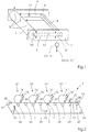
- Fig. 1 shows a schematic diagram of the device according to the invention.
- a roller 1 with a contact pressure 3 this is supported at one end by two two-armed levers 4, 5.
- the two-armed levers 4, 5 are mounted on side parts 6 and 7 by means of bearings 14.
- a cross connection 8 At the other ends of the two-armed levers 4, 5 there is a cross connection 8, which is acted upon by a force generating element 9, 9 ', 9 "with a force 10, 10', 10".
- This can be a force-generating element 9 for generating a permanent force 10, a force-generating element 9 'for generating a force 10' opposite to the permanent force 10, or a force-generating element 9 "for generating a variable force 10".
- the representation here is symbolic in nature and will be explained in more detail below.
- the actuating movement of the roller 1 is shown by means of a double arrow 20 and the Adjustment movement of the opposite ends of the levers 4, 5 with the double arrow 21.
- Forces 10, 10 ', 10 "and actuating movements 20 and 21 are used to engage the roller 1 interacting component, not shown here, with the symbolized by three arrows Apply pressure 3.
- the three arrows 3 are intended to illustrate that the Contact pressure 3 is evenly distributed over the entire width of the roller. This is the Main purpose of the invention, which is achieved in that the power transmission by means of the two-armed levers 4, 5 in such a way that the roller 1 with uniform Forces is applied.
- the diagram in FIG. 2 shows a printing press 2 with a carrier 17 for transporting printing substrates 16 through the printing press 2 in the direction of the arrow 31.
- the printing substrates 16 change from one printing module 19, 19 ', 19 “, 19”' to the other conveyed and thereby printed by cylinders 18, 18 ', 18 ", 18"' of the printing modules 19, 19 ', 19 “, 19”' with partial color images 15, 15 ', 15 ", 15”', which together result in color printing.
- An exact contact pressure 3 and a vibration-free guidance of the printing substrates 16 are required.
- the invention proposes rollers 10, 10 ', 10 ", 10"' which are mounted on the principle described above.
- the carrier 17 is placed over a variety of roles.
- a roller 22 is used to drive of the carrier 17 in the direction of arrow 23. Another role is by the effect a tensioning roller 25.
- a roller 26 pivotable transversely to its axis of rotation is for lateral adjustment of the tape run of the carrier 17 is provided.
- a pulley 27 interacts with a roller 28.
- the roller 28 is used to hang up Print substrates 16 which are to be printed.
- Guide rollers 29 cause certain wrapping of cylinders 18, 18 ', 18 ", 18"' corresponding to the partial color images 15, 15 ', 15 ", 15”' a print image in the form of toner particles for transfer wear on the printing substrates 16.
- the cylinders 15, 15 ', 15 ", 15”' Provide the toner particles directly or via further cylinders (not shown) become.
- the arrows 32 show the direction of rotation of the cylinders 15, 15 ', 15 ", 15”'.
- rollers 10, 10 ', 10 ", 10"' designed as pressure rollers are provided, which can be switched on and off on the underside of the carrier 17.
- Another role 30 is used to remove a printing substrate 16 from the carrier 17.
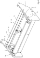
- Fig. 3 shows an embodiment of the device according to the invention with force-generating elements 9 and 9 ', which are designed as a weight 11 and as a pneumatic cylinder 12.
- the weight 11 pulls down and thereby generates the contact pressure 3 of the roller 10.
- the element 9 ' serves to generate the counterforce 10' to regulate this contact pressure 3 or to switch off the contact pressure.
- This element 9 ' is designed as a pneumatic cylinder 12.
- the actuating movement of the pneumatic cylinder 12 is shown by means of the double arrow 34. If the pneumatic cylinder 12 is not active, the contact pressure 3 is generated by the weight 11.
- the two two-armed levers 4, 5 are attached to side parts 6, 7, which are connected to one another by cross struts 33. In this way, the device is designed such that it can be used as a whole in a machine, for example by fastening the side parts 6, 7 in the machine.
- the other functions and the other components reference is made to the basic diagrams above.
- FIG. 4 shows a further exemplary embodiment of the invention, in which an element 9 "for generating a variable force 10" is arranged.
- This element is a pneumatic cylinder 13, which is arranged in the middle of the cross connection 8.
- the cross connection 8 is rotatably suspended on the two-armed levers 4, 5 and has spring properties. These measures result in a very good distribution of force and absorption of shocks and other stresses.
- the levers 4, 5 are supported by means of bearings 14 in side parts 6, 7, which are connected to one another by means of cross struts 33.
- the actuating movement of the pneumatic cylinder 13 is indicated by the double arrow 34.
- the pneumatic cylinder 13 applies the entire force required to set the contact pressure 3.
- the pneumatic cylinder 13 is designed such that it can turn the roller 10 on and off.
Landscapes
- Engineering & Computer Science (AREA)
- Mechanical Engineering (AREA)
- Delivering By Means Of Belts And Rollers (AREA)
- Rotary Presses (AREA)
- Inking, Control Or Cleaning Of Printing Machines (AREA)
- Unwinding Webs (AREA)
- Rolls And Other Rotary Bodies (AREA)
- Electrostatic Charge, Transfer And Separation In Electrography (AREA)
- Color Electrophotography (AREA)
Abstract
Description
Die Erfindung betrifft eine Vorrichtung zur Beaufschlagung einer Walze einer drucktechnischen Maschine mit einer Anpreßkraft und eine Druckmaschine mit einer derartigen Vorrichtung.The invention relates to a device for loading a roller of a printing technology Machine with a contact pressure and a printing machine with such Contraption.
Bei drucktechnischen Maschinen müssen Walzen oft mit einer Anpreßkraft beaufschlagt werden, wobei es in vielen Fällen für die Druckqualität entscheidend ist, daß die Anpreßkraft über die Breite einer solchen Walze gesehen konstant ist.In the case of printing machines, rollers often have to be applied with a contact pressure be, and in many cases it is crucial for the print quality that the Contact force is constant across the width of such a roller.
Ein wichtiges Beispiel für derartige Walzen sind Andrückwalzen, die dazu dienen, von einem Träger geförderte Drucksubstrate gegen die Zylinder mehrerer Druckmodule zu drücken, um die von den Druckmodulen erzeugten Teilfarbenbilder möglichst gleichmäßig und registergenau auf die Drucksubstrate zu übertragen.An important example of such rollers are pressure rollers, which are used by a substrate conveyed printing substrates against the cylinders of several printing modules Press to make the part-color images generated by the print modules as even as possible and to be transferred to the printing substrates in exact register.
Für den vorgenannten Zweck ist es bekannt, Andrückwalzen entweder einzeln mittels Federn gegen die Zylinder zu drücken oder die Andrückwalzen alle auf einem Tragelement anzuordnen und dieses mit Federn zu beaufschlagen, damit die Andrückwalzen gemeinsam gegen die Zylinder gedrückt werden. Bei beiden Anordnungen wird die Anpreßkraft dadurch erzeugt, daß von den Federn unmittelbar eine entsprechende Kraft auf verschiebbar angeordnete Lager der Andrückwalzen übertragen wird. Eine konstante Anpreßkraft über die Breite der Walzen ist dadurch jedoch nicht in befriedigender Weise erzielbar, insbesondere dann nicht, wenn diese wegen einer geforderten hohen Druckqualität in sehr präziser Weise erforderlich ist. For the aforementioned purpose, it is known to use pressure rollers either individually Pressing springs against the cylinders or the pressure rollers all on one support element to arrange and to apply this to springs so that the pressure rollers pressed together against the cylinders. In both arrangements, the Contact force generated by a corresponding force from the springs is transferred to displaceably arranged bearings of the pressure rollers. A constant Contact pressure across the width of the rollers is not, however, satisfactory Way achievable, especially not if this is due to a required high Print quality in a very precise way is required.
Weiterhin ist es bekannt, an verschiebbar angeordneten Lagern von Walzen aktive Aktuatoren einzusetzen, welche diese unmittelbare Kraftbeaufschlagung übernehmen. Damit ist es zwar möglich, über die Breite der Walzen eine wesentlich konstantere Anpreßkraft zu erzielen, jedoch muß dazu ein großer Aufwand an teurer Sensorik und Steuerung betrieben werden.Furthermore, it is known to be active on displaceably arranged bearings of rollers Use actuators that take over this direct application of force. This makes it possible to have a much more constant width across the rolls To achieve contact pressure, however, this requires a large amount of expensive sensors and Control operated.
Der Erfindung liegt daher die Aufgabe zugrunde, eine Vorrichtung der eingangs genannten Art derart auszubilden, daß mit geringem Aufwand eine konstante Anpreßkraft über die Breite der Walzen erzielbar ist.The invention is therefore based on the object of a device at the outset mentioned type in such a way that a constant contact pressure with little effort can be achieved across the width of the rollers.
Die Aufgabe wird erfindungsgemäß dadurch gelöst, daß die Walze an den einen Enden zweier zweiarmiger Hebel drehbar gelagert ist, daß die zweiarmigen Hebel an Seitenteilen drehbar gelagert sind und daß an den anderen Enden der zweiarmigen Hebel eine Querverbindung angeordnet ist, an die mindestens ein krafterzeugendes Element angreift.The object is achieved in that the roller at one end two two-armed lever is rotatably mounted that the two-armed lever on side parts are rotatably mounted and that at the other ends of the two-armed lever one Cross connection is arranged to the at least one force-generating element attacks.
Durch die erfindungsgemäße Hebelübertragung der Kräfte verteilen sich diese gleichmäßig auf die jeweilige Walze. Dabei werden auch Ungenauigkeiten der Abmessungen von Walzen oder den mit diesen zusammenwirkenden Elementen aufgenommen, ebenso Stöße, die beispielsweise durch Vorder- oder Hinterkanten von Drucksubstraten entstehen.The lever transmission of the forces according to the invention distributes them evenly on the respective roller. This also includes inaccuracies in dimensions by rollers or the elements interacting with them, as well Shocks that occur, for example, from the front or rear edges of printing substrates.
Diese Vorteile werden durch Weiterbildungen und zweckmäßige Ausgestaltungen in noch besserer Weise erzielt, auf weitere Vorteile wird verwiesen.These advantages are shown in further training and practical refinements achieved even better, reference is made to further advantages.
Das krafterzeugende Element kann auf verschiedene Weise ausgebildet werden. Ein Vorschlag sieht vor, daß das krafterzeugende Element zur Aufbringung einer permanenten Kraft ausgebildet ist, die derart bemessen ist, daß über die zweiarmigen Hebel die Anpreßkraft entsteht. Beispielsweise kann eine permanente Kraft dadurch erzeugt werden, daß das krafterzeugende Element ein Gewicht ist. Eine derart erzeugte Kraft ist immer konstant, weist kaum stellungsabhängige Unterschiede und keine Hysterese auf, wie dies bei Federn der Fall ist.The force-generating element can be designed in various ways. On Proposal provides that the force-generating element to apply a permanent Force is formed, which is dimensioned such that the two-armed lever the contact pressure arises. For example, it can create a permanent force that the force-generating element is a weight. A force generated in this way is always constant, shows hardly any position-dependent differences and no hysteresis, as is the case with springs.
Verschiedene Anpreßkräfte lassen sich dadurch einstellen, daß ein weiteres krafterzeugendes Element angeordnet ist, durch das eine der permanenten Kraft entgegenwirkende Kraft erzeugbar ist. Mittels einer derartigen entgegenwirkenden Kraft läßt sich die Anpreßkraft auch abstellen, wenn erstere größer als die Gewichtskraft ist. Eine solche Abstellung hat den Vorteil, daß es bei einem Stillstand der Maschine nicht zu einer bleibenden Deformierung von Oberflächen durch eine längere Zeit fortwirkende Kraftbeaufschlagung kommen kann.Different contact forces can be adjusted by the fact that another force-generating Element is arranged through which one counteracts the permanent force Force can be generated. By means of such an opposing force, the Also turn off the contact pressure if the former is greater than the weight. Such Switching off has the advantage that it does not become permanent when the machine is at a standstill Deformation of surfaces due to a prolonged application of force can come.
Das krafterzeugende Element für die entgegenwirkende Kraft ist zweckmäßigerweise ein Pneumatikzylinder. Dieser ist bezüglich der Anpreßkraft wie eines An- und Abstellens einer Walze gut steuerbar und kann derart ausgebildet sein, daß er gleichzeitig als Dämpfungselement wirkt. Auf diese Weise wird das Auftreten von Schwingungen verhindert, beispielsweise solchen, die durch Drucksubstratvorderkanten oder -hinterkanten angeregt werden könnten.The force-generating element for the counteracting force is expedient a pneumatic cylinder. In terms of the contact pressure, this is like starting and stopping a roller well controllable and can be designed such that it simultaneously as Damping element works. This way the occurrence of vibrations prevents, for example, those caused by printing substrate leading or trailing edges could be stimulated.
Eine alternative Ausgestaltung des krafterzeugenden Elements sieht vor, daß dieses zur Aufbringung einer variablen Kraft ausgebildet ist, wobei diese derart einstellbar ist, daß eine gewünschte Anpreßkraft erzielbar ist. Vorzugsweise ist die variable Kraft auch derart einstellbar, daß die Anpreßkraft abstellbar ist, also die Walze von dem mit ihr zusammenwirkenden Element weggefahren werden kann. Auch dies dient der Verhinderung der bereits oben erwähnten Deformierung von Oberflächen.An alternative embodiment of the force-generating element provides that this for Application of a variable force is formed, which is adjustable such that a desired contact pressure can be achieved. Preferably the variable force is too adjustable so that the contact pressure can be switched off, that is, the roller with it interacting element can be moved away. This also serves to prevent this the deformation of surfaces mentioned above.
Wird ein krafterzeugendes Element an der Querverbindung mittig angeordnet, so wird auf einfache Weise eine sehr konstante Anpreßkraft entlang einer Walze erzielt.If a force-generating element is arranged centrally on the cross-connection, then easily achieved a very constant contact force along a roller.
Auch die variable Kraft wird vorzugsweise mittels eines Pneumatikzylinders erzeugt, mit dem verschiedene Kräfte wie ein An- und Abstellen einer Walze leicht erzielbar sind. Auch in diesem Fall läßt sich durch den Pneumatikzylinder eine gute Dämpfungswirkung erzielen.The variable force is also preferably generated by means of a pneumatic cylinder, with which various forces such as starting and stopping a roller can be easily achieved are. In this case too, the pneumatic cylinder has a good damping effect achieve.
Wird die Querverbindung als federndes Element ausgebildet, so wird eine besonders gute Aufnahme von Stößen und Druckschwankungen sowie ein sehr guter Ausgleich von Ungenauigkeiten erzielt. Diesem Zweck dient es auch, wenn die Querverbindung drehbar mit den Hebeln verbunden ist, wobei die Querverbindung parallel zur Walze verlaufen sollte.If the cross connection is designed as a resilient element, one becomes special good absorption of shocks and pressure fluctuations as well as a very good compensation achieved by inaccuracies. It also serves this purpose if the cross connection is rotatably connected to the levers, the cross connection parallel to the roller should run.
Außer der Ausbildung der vorgenannten Pneumatikzylinder als Dämpfungselemente können selbstverständlich auch separate Dämpfungselemente angeordnet werden. Einer Verhinderung von Schwingungen dient es auch, wenn die Lagerungen der Hebel in den Seitenteilen als Gleitlager ausgebildet sind. Die Seitenteile können Gehäusewandungen oder separate Bauteile sein, die mit den Gehäusewandungen verbunden sind.In addition to the design of the aforementioned pneumatic cylinders as damping elements separate damping elements can of course also be arranged. One It also serves to prevent vibrations when the bearings of the levers in the Side parts are designed as plain bearings. The side panels can have housing walls or be separate components that are connected to the housing walls.
Eine besonders zweckmäßige Anwendung der Vorrichtung sieht vor, diese zum Andrücken der Andrückwalzen zu verwenden, wobei die Anpreßkraft erzeugt wird, die für eine optimale Übertragung von Teilfarbenbildern auf ein Drucksubstrat erforderlich ist. Selbstverständlich gibt es in einer drucktechnischen Maschine noch weitere Einsatzgebiete der Erfindung. Der vorgenannte Einsatzzweck ist jedoch besonders bedeutsam, da die gleichmäßige und präzise Krafteinstellung für die Druckqualität eine ausschlaggebende Rolle spielt. Deshalb wird auch vorgeschlagen, eine Druckmaschine, insbesondere eine elektrophotografische Druckmaschine mit einer vorgenannten Vorrichtung auszustatten, wobei die Walzen an einem Träger für Drucksubstrate gegenüberliegend von Zylindern angeordnet sind, welche zur Übertragung der Teilfarbenbilder auf Drucksubstrate ausgebildet sind.A particularly useful application of the device provides for this Use pressure of the pressure rollers, whereby the contact pressure is generated, the required for optimal transfer of partial color images to a printing substrate is. Of course there are other areas of application in a printing machine the invention. However, the aforementioned purpose is particularly important, because the uniform and precise force setting for the print quality is crucial Role play. Therefore, it is also proposed to use a printing press, in particular an electrophotographic printing machine with an aforementioned device equip, the rollers on a support for printing substrates opposite of cylinders are arranged, which for transferring the partial color images Print substrates are formed.
Die vorgenannten Ausgestaltungen sind selbstverständlich nur beispielhaft. Beispielsweise können auch andere dem Fachmann bekannte krafterzeugende Elemente eingesetzt werden. The aforementioned configurations are of course only examples. For example other force-generating elements known to the person skilled in the art can also be used become.
Die Erfindung wird nachfolgend anhand der Zeichnung erläutert. Es zeigen
- Fig. 1
- eine Prinzipskizze der erfindungsgemäßen Vorrichtung,
- Fig. 2
- ein Schema einer Druckmaschine mit Transport der Drucksubstrate mittels eines Trägers,
- Fig. 3
- ein Ausführungsbeispiel der erfindungsgemäßen Vorrichtung und
- Fig. 4
- ein weiteres Ausführungsbeispiel der erfindungsgemäßen Vorrichtung.
- Fig. 1
- a schematic diagram of the device according to the invention,
- Fig. 2
- 1 shows a diagram of a printing press with transport of the printing substrates by means of a carrier,
- Fig. 3
- an embodiment of the device according to the invention and
- Fig. 4
- another embodiment of the device according to the invention.
Fig. 1 zeigt eine Prinzipskizze der erfindungsgemäßen Vorrichtung. Zur Beaufschlagung
einer Walze 1 mit einer Anpreßkraft 3 ist diese an den einen Enden von zwei
zweiarmigen Hebeln 4, 5 gelagert. Die zweiarmigen Hebel 4, 5 sind mittels Lagerungen
14 an Seitenteilen 6 und 7 gelagert. An den anderen Enden der zweiarmigen Hebel 4, 5
befindet sich eine Querverbindung 8, welche durch ein krafterzeugendes Element 9, 9',
9" mit einer Kraft 10, 10', 10" beaufschlagt wird. Dabei kann es sich um ein krafterzeugendes
Element 9 zur Erzeugung einer permanenten Kraft 10, um ein krafterzeugendes
Element 9' zur Erzeugung einer der permanenten Kraft 10 entgegengerichteten
Kraft 10' oder um ein krafterzeugendes Element 9" zur Erzeugung einer variablen Kraft
10" handeln. Die Darstellung ist hier symbolischer Natur, sie wird weiter unten noch
näher ausgeführt. Fig. 1 shows a schematic diagram of the device according to the invention. To act on a roller 1 with a
Die Stellbewegung der Walze 1 ist mittels eines Doppelpfeils 20 eingezeichnet und die
Stellbewegung der gegenüberliegenden Enden der Hebel 4, 5 mit dem Doppelpfeil 21.
Kräfte 10, 10', 10" und Stellbewegungen 20 und 21 dienen dazu, ein mit der Walze 1
zusammenwirkendes, hier nicht dargestelltes Bauteil mit der durch drei Pfeile symbolisierten
Anpreßkraft 3 zu beaufschlagen. Die drei Pfeile 3 sollen verdeutlichen, daß die
Anpreßkraft 3 über die gesamte Breite der Walze gleichmäßig verteilt ist. Dies ist der
Hauptzweck der Erfindung, welcher dadurch erzielt wird, daß die Kraftübertragung
mittels der zweiarmigen Hebel 4, 5 derart erfolgt, daß die Walze 1 mit gleichmäßigen
Kräften beaufschlagt wird.The actuating movement of the roller 1 is shown by means of a
Das Schema in Fig. 2 zeigt eine Druckmaschine 2 mit einem Träger 17 zum Transport
von Drucksubstraten 16 durch die Druckmaschine 2 in Richtung des Pfeils 31. Dabei
werden die Drucksubstrate 16 von einem Druckmodul 19, 19', 19", 19"' zum anderen
befördert und dabei von Zylindern 18, 18', 18", 18"' der Druckmodule 19, 19', 19",
19"' mit Teilfarbenbildern 15, 15', 15", 15"' bedruckt, welche gemeinsam den
Farbdruck ergeben. Dabei ist ein exakter Anpreßdruck 3 und eine schwingungsfreie
Führung der Drucksubstrate 16 erforderlich. Zu diesem Zweck schlägt die Erfindung
Walzen 10, 10', 10", 10"' vor, die nach dem oben dargestellten Prinzip gelagert sind.The diagram in FIG. 2 shows a
Der Träger 17 ist über eine Vielzahl von Rollen gelegt. Eine Rolle 22 dient zum Antrieb
des Trägers 17 in Richtung des Pfeiles 23. Eine weitere Rolle dient durch die Wirkung
einer Spannrolle 25. Eine quer zu ihrer Drehachse schwenkbare Rolle 26 ist zur
seitlichen Einstellung des Bandlaufs des Trägers 17 vorgesehen. Eine Umlenkrolle 27
wirkt mit einer Rolle 28 zusammen. Die Rolle 28 dient zum Auflegen von
Drucksubstraten 16, welche bedruckt werden sollen. Führungsrollen 29 bewirken ein
gewisses Umschlingen von Zylindern 18, 18', 18", 18"', die entsprechend den Teilfarbenbildern
15, 15', 15", 15"' ein Druckbild in Form von Tonerpartikeln zur Übertragung
auf die Drucksubstrate 16 tragen. Dabei können die Zylinder 15, 15', 15", 15"'
unmittelbar oder über weitere Zylinder (nicht dargestellt) mit den Tonerpartikeln versehen
werden. Die Pfeile 32 zeigen die Drehrichtung der Zylinder 15, 15', 15", 15"'.The
Damit während des Druckbetriebes eine definierte Pressung zwischen dem Träger 17
mit dem darauf befindlichen Drucksubstraten 16 und den Zylindern 18, 18', 18", 18"'
vorhanden ist, sind als Andrückwalzen ausgebildete Walzen 10, 10', 10", 10"' vorgesehen,
die an die Unterseite des Trägers 17 an- und abstellbar sind. Eine weitere Rolle
30 dient zur Abnahme eines Drucksubstrats 16 vom Träger 17. So that a defined pressure between the
Fig. 3 zeigt ein Ausführungsbeispiel der erfindungsgemäßen Vorrichtung mit krafterzeugenden
Elementen 9 und 9', die als Gewicht 11 und als Pneumatikzylinder 12
ausgebildet sind. Das Gewicht 11 zieht nach unten und erzeugt dadurch die Anpreßkraft
3 der Walze 10. Zur Regulierung dieser Anpreßkraft 3 oder zur Abstellung der Anpressung
dient das Element 9' zur Erzeugung der Gegenkraft 10'. Dieses Element 9' ist als
Pneumatikzylinder 12 ausgebildet. Die Stellbewegung des Pneumatikzylinders 12 ist
mittels des Doppelpfeils 34 eingezeichnet. Ist der Pneumatikzylinder 12 nicht aktiv, so
wird die Anpreßkraft 3 durch das Gewicht 11 erzeugt. Die beiden zweiarmigen Hebel 4,
5 sind an Seitenteilen 6, 7 befestigt, welche durch Querstreben 33 miteinander
verbunden sind. Auf diese Weise ist die Vorrichtung derart ausgebildet, daß sie als
Gesamtes in eine Maschine eingesetzt werde kann, indem beispielsweise die Seitenteile
6, 7 in der Maschine befestigt werden. Bezüglich der übrigen Funktionen und der
übrigen Bauteile wird auf die obigen Prinzipdarstellungen verwiesen. Fig. 3 shows an embodiment of the device according to the invention with force-generating
Fig. 4 zeigt ein weiteres Ausführungsbeispiel der Erfindung, bei der ein Element 9" zur
Erzeugung einer variablen Kraft 10" angeordnet ist. Dieses Element ist ein Pneumatikzylinder
13, welcher in der Mitte der Querverbindung 8 angeordnet ist. Die
Querverbindung 8 ist drehbar an den zweiarmigen Hebeln 4, 5 aufgehängt und weist
Federeigenschaften auf. Durch diese Maßnahmen kommt es zu einer sehr guten Kraftverteilung
und zu einer Aufnahme von Stößen und sonstigen Beanspruchungen. Bei
dieser Ausgestaltung ist es wichtig, daß der Pneumatikzylinder 13 dämpfende Eigenschaften
aufweist. Auch hier sind die Hebel 4, 5 mittels Lagerungen 14 in Seitenteilen 6,
7 gelagert, welche mittels Querstreben 33 miteinander verbunden sind. Die Stellbewegung
des Pneumatikzylinders 13 ist durch den Doppelpfeil 34 angezeigt. In diesem Fall
bringt der Pneumatikzylinder 13 die gesamte Kraft auf, die erforderlich ist, um die
Anpreßkraft 3 einzustellen. Weiterhin ist der Pneumatikzylinder 13 derart ausgebildet,
daß er die Walze 10 an- und abstellen kann. Auch hier wird bezüglich weiterer
Elemente und Funktionen auf die oben genannte Prinzipdarstellung verwiesen. FIG. 4 shows a further exemplary embodiment of the invention, in which an
- 1, 1', 1", 1"'1, 1 ', 1 ", 1"'
- WalzenRollers
- 22nd
- drucktechnische Maschine, insbesondere Druckmaschineprinting machine, in particular printing machine
- 33rd
- AnpreßkraftContact pressure
- 4, 54, 5
- zweiarmige Hebeltwo-armed lever
- 6, 76, 7
- SeitenteileSide panels
- 88th
- QuerverbindungCross-connection
- 9, 9', 9"9, 9 ', 9 "
- krafterzeugendes Elementforce-generating element
- 99
- Element mit permanenter KraftElement with permanent strength
- 9'9 '
- Element mit GegenkraftElement with counterforce
- 9"9 "
- Element mit variabler KraftVariable force element
- 10, 10', 10"10, 10 ', 10 "
- Kraftforce
- 1010th
- permanente Kraftpermanent strength
- 10'10 '
- der permanenten Kraft entgegenwirkende Kraftforce counteracting the permanent force
- 10"10 "
- variable Kraftvariable force
- 1111
- GewichtWeight
- 1212th
- Pneumatikzylinder für die Erzeugung der entgegenwirkenden KraftPneumatic cylinder for generating the counteracting force
- 1313
- Pneumatikzylinder für die Erzeugung einer variablen KraftPneumatic cylinder for the generation of a variable force
- 1414
- Lagerungen der Hebel in den SeitenteilenBearings of the levers in the side parts
- 15, 15', 15", 15'''15, 15 ', 15 ", 15 '' '
- TeilfarbenbilderPart color images
- 1616
- Drucksubstrat Printing substrate
- 1717th
- Trägercarrier
- 18, 18' 18", 18"'18, 18 ' 18 ", 18" '
- Zylinder zur Übertragung der Teilfarbenbilder auf DrucksubstrateCylinder for transferring the partial color images to printing substrates
- 19, 19' 19", 19"'19, 19 ' 19 ", 19" '
- DruckmodulePrinting modules
- 2020th
- Stellbewegungen der WalzeAdjustment movements of the roller
- 2121
- Stellbewegungen der gegenüberliegenden Enden der HebelAdjustment movements of the opposite ends of the levers
- 2222
- Rolle für AntriebRoller for drive
- 2323
- Pfeil: Antriebsrichtung des TrägersArrow: drive direction of the carrier
- 2525th
- SpannrolleIdler pulley
- 2626
- Rolle zur seitlichen Einstellung des TrägersRoller for lateral adjustment of the carrier
- 2727
- UmlenkrollePulley
- 2828
- Rolle zum Auflegen von DrucksubstratenRoll for printing substrates
- 2929
- FührungsrollenLeadership roles
- 3030th
- Rolle zur Abnahme eines DrucksubstratesRoll for removing a printing substrate
- 3131
- Pfeil: Transport der DrucksubstrateArrow: Transport of the printing substrates
- 3232
- Pfeile: Drehrichtung der ZylinderArrows: Direction of rotation of the cylinders
- 3333
- QuerstrebenCross struts
- 3434
- Doppelpfeil: Stellbewegung des PneumatikzylindersDouble arrow: actuating movement of the pneumatic cylinder
Claims (18)
dadurch gekennzeichnet, daß die Walze (1, 1', 1", 1"') an den einen Enden zweier zweiarmiger Hebel (4, 5) drehbar gelagert ist, daß die zweiarmigen Hebel (4, 5) an Seitenteilen (6, 7) drehbar gelagert sind und daß an den anderen Enden der zweiarmigen Hebel (4, 5) eine Querverbindung (8) angeordnet ist, an die mindestens ein krafterzeugendes Element (9, 9', 9") angreift.Device for acting on a roller (1, 1 ', 1 ", 1"') of a printing machine (2) with a contact pressure (3),
characterized in that the roller (1, 1 ', 1 ", 1"') is rotatably mounted on one end of two two-armed levers (4, 5), that the two-armed lever (4, 5) on side parts (6, 7 ) are rotatably mounted and that at the other ends of the two-armed lever (4, 5) a cross connection (8) is arranged, on which at least one force-generating element (9, 9 ', 9 ") engages.
dadurch gekennzeichnet, daß das krafterzeugende Element (9) zur Aufbringung einer permanenten Kraft (10) ausgebildet ist, die derart bemessen ist, daß über die zweiarmigen Hebel (4, 5) die Anpreßkraft (3) entsteht.Device according to claim 1,
characterized in that the force-generating element (9) is designed to apply a permanent force (10) which is dimensioned such that the pressing force (3) is created via the two-armed levers (4, 5).
dadurch gekennzeichnet, daß das krafterzeugende Element (9) ein Gewicht (11) ist.Device according to claim 2,
characterized in that the force-generating element (9) is a weight (11).
dadurch gekennzeichnet, daß ein weiteres krafterzeugendes Element (9') angeordnet ist, durch das eine der permanenten Kraft (10) entgegenwirkende Kraft (10') erzeugbar ist. Device according to claim 2 or 3,
characterized in that a further force-generating element (9 ') is arranged, by means of which a force (10') which counteracts the permanent force (10) can be generated.
dadurch gekennzeichnet, daß die entgegenwirkende Kraft (10') der Einstellung der Anpreßkraft (3) dient.Device according to claim 4,
characterized in that the counteracting force (10 ') serves to adjust the contact pressure (3).
dadurch gekennzeichnet, daß die entgegenwirkende Kraft (10') der Abstellung der Anpreßkraft (3) dient.Device according to claim 4 or 5,
characterized in that the counteracting force (10 ') serves to switch off the contact pressure (3).
dadurch gekennzeichnet, daß das krafterzeugende Element (9') ein Pneumatikzylinder (12) ist.Device according to one of claims 4 to 6,
characterized in that the force-generating element (9 ') is a pneumatic cylinder (12).
dadurch gekennzeichnet, daß das krafterzeugende Element (9") zur Aufbringung einer variablen Kraft (10") ausgebildet ist, wobei diese derart einstellbar ist, daß eine gewünschte Anpreßkraft (3) erzielbar ist.Device according to claim 1,
characterized in that the force-generating element (9 ") is designed to apply a variable force (10"), this being adjustable such that a desired contact pressure (3) can be achieved.
dadurch gekennzeichnet, daß die variable Kraft (10") derart einstellbar ist, daß die Anpreßkraft (3) abgestellt ist.Device according to claim 8,
characterized in that the variable force (10 ") is adjustable such that the contact pressure (3) is switched off.
dadurch gekennzeichnet, daß ein krafterzeugendes Element(9") an der Querverbindung (8) mittig angeordnet ist.Device according to claim 8 or 9,
characterized in that a force-generating element (9 ") is arranged centrally on the cross-connection (8).
dadurch gekennzeichnet, daß das krafterzeugende Element (9") ein Pneumatikzylinder (13) ist. Device according to one of claims 8 to 10,
characterized in that the force-generating element (9 ") is a pneumatic cylinder (13).
dadurch gekennzeichnet, daß die Querverbindung (8) als federndes Element ausgebildet ist.Device according to one of claims 1 to 11,
characterized in that the cross connection (8) is designed as a resilient element.
dadurch gekennzeichnet, daß die Querverbindung (8) drehbar mit den Hebeln (4, 5) verbunden ist.Device according to one of claims 1 to 12,
characterized in that the cross-connection (8) is rotatably connected to the levers (4, 5).
dadurch gekennzeichnet, daß Dämpfüngselemente zur Dämpfung von Walzenschwingungen angeordnet sind.Device according to one of claims 1 to 13,
characterized in that damping elements for damping roller vibrations are arranged.
dadurch gekennzeichnet, daß der Pneumatikzylinder (12 oder 13) als Dämpfungselement wirkend ausgebildet ist.Device according to one of claims 7 or 11 to 14,
characterized in that the pneumatic cylinder (12 or 13) is designed to act as a damping element.
dadurch gekennzeichnet, daß die Lagerungen (14) der Hebel (4, 5) in den Seitenteilen (6, 7) als Gleitlager ausgebildet sind.Device according to one of claims 1 to 15,
characterized in that the bearings (14) of the levers (4, 5) in the side parts (6, 7) are designed as plain bearings.
dadurch gekennzeichnet, daß die Walzen (1, 1', 1", 1"') Andrückwalzen zur Erzeugung der Anpreßkraft (3) für die Übertragung von Teilfarbenbildern (15, 15', 15", 15"') auf ein Drucksubstrat (16) sind und die Anpreßkraft (3) zur Bewirkung dieser Übertragung bemessen ist. Device according to one of claims 1 to 16,
characterized in that the rollers (1, 1 ', 1 ", 1"') pressure rollers for generating the contact pressure (3) for the transfer of partial color images (15, 15 ', 15 ", 15"') to a printing substrate (16 ) and the contact pressure (3) is dimensioned to effect this transmission.
dadurch gekennzeichnet, daß die Walzen (1, 1', 1", 1"') an einem Träger (17) für Drucksubstrate gegenüberliegend von Zylindern (18, 18', 18", 18"') angeordnet sind, welche zur Übertragung der Teilfarbenbilder (15, 15', 15", 15"') auf Drucksubstrate (16) ausgebildet sind.Printing machine (2), in particular electrophotographic printing machine, with a device according to claim 17,
characterized in that the rollers (1, 1 ', 1 ", 1"') are arranged on a support (17) for printing substrates opposite cylinders (18, 18 ', 18 ", 18"') which are used to transmit the Partial color images (15, 15 ', 15 ", 15"') are formed on printing substrates (16).
Applications Claiming Priority (4)
| Application Number | Priority Date | Filing Date | Title |
|---|---|---|---|
| DE10024092 | 2000-05-18 | ||
| DE10024092 | 2000-05-18 | ||
| DE10059889A DE10059889A1 (en) | 2000-05-18 | 2000-12-01 | Device for applying a pressing force to a roller of a printing machine and printing machine with such a device |
| DE10059889 | 2000-12-01 |
Publications (3)
| Publication Number | Publication Date |
|---|---|
| EP1155830A2 true EP1155830A2 (en) | 2001-11-21 |
| EP1155830A3 EP1155830A3 (en) | 2003-01-02 |
| EP1155830B1 EP1155830B1 (en) | 2006-05-31 |
Family
ID=26005707
Family Applications (1)
| Application Number | Title | Priority Date | Filing Date |
|---|---|---|---|
| EP01111492A Expired - Lifetime EP1155830B1 (en) | 2000-05-18 | 2001-05-11 | Printing machine with means for applying a pressure force on a printing press cylinder |
Country Status (5)
| Country | Link |
|---|---|
| US (1) | US20020020314A1 (en) |
| EP (1) | EP1155830B1 (en) |
| JP (1) | JP2002023522A (en) |
| AT (1) | ATE327889T1 (en) |
| DE (1) | DE50109925D1 (en) |
Families Citing this family (2)
| Publication number | Priority date | Publication date | Assignee | Title |
|---|---|---|---|---|
| DE102016215988A1 (en) * | 2016-08-25 | 2018-03-01 | Gallus Druckmaschinen Gmbh | Machining plant and label printing machine with such a processing plant |
| DE102016215986A1 (en) * | 2016-08-25 | 2018-03-01 | Gallus Druckmaschinen Gmbh | Machining plant and label printing machine with such a processing plant |
Citations (5)
| Publication number | Priority date | Publication date | Assignee | Title |
|---|---|---|---|---|
| US2213130A (en) * | 1938-05-21 | 1940-08-27 | American Stay Company | Printing press |
| GB634213A (en) * | 1947-04-24 | 1950-03-15 | Astra Ivanowna Sark | Improvements relating to multi-colour printing machines |
| FR1494327A (en) * | 1966-07-29 | 1967-09-08 | Heurtey Sa | Improvements made to belt tensioning devices or similar product, in continuous treatment facilities |
| CH493414A (en) * | 1968-07-30 | 1970-07-15 | Kleinewefers Soehne J | Dancer roll |
| DE3232484A1 (en) * | 1981-09-03 | 1983-03-10 | Basf Ag, 6700 Ludwigshafen | Winding device for flat strips |
-
2001
- 2001-05-07 US US09/850,046 patent/US20020020314A1/en not_active Abandoned
- 2001-05-11 EP EP01111492A patent/EP1155830B1/en not_active Expired - Lifetime
- 2001-05-11 DE DE50109925T patent/DE50109925D1/en not_active Expired - Lifetime
- 2001-05-11 AT AT01111492T patent/ATE327889T1/en not_active IP Right Cessation
- 2001-05-14 JP JP2001143612A patent/JP2002023522A/en active Pending
Patent Citations (5)
| Publication number | Priority date | Publication date | Assignee | Title |
|---|---|---|---|---|
| US2213130A (en) * | 1938-05-21 | 1940-08-27 | American Stay Company | Printing press |
| GB634213A (en) * | 1947-04-24 | 1950-03-15 | Astra Ivanowna Sark | Improvements relating to multi-colour printing machines |
| FR1494327A (en) * | 1966-07-29 | 1967-09-08 | Heurtey Sa | Improvements made to belt tensioning devices or similar product, in continuous treatment facilities |
| CH493414A (en) * | 1968-07-30 | 1970-07-15 | Kleinewefers Soehne J | Dancer roll |
| DE3232484A1 (en) * | 1981-09-03 | 1983-03-10 | Basf Ag, 6700 Ludwigshafen | Winding device for flat strips |
Also Published As
| Publication number | Publication date |
|---|---|
| EP1155830B1 (en) | 2006-05-31 |
| ATE327889T1 (en) | 2006-06-15 |
| EP1155830A3 (en) | 2003-01-02 |
| JP2002023522A (en) | 2002-01-23 |
| DE50109925D1 (en) | 2006-07-06 |
| US20020020314A1 (en) | 2002-02-21 |
Similar Documents
| Publication | Publication Date | Title |
|---|---|---|
| DE60122438T2 (en) | Device for regulating the gap between two rollers | |
| DE3902923C2 (en) | Sheet guide drum for sheet-fed rotary printing machines | |
| DE2235418A1 (en) | DEVICE FOR CROSS TRAINING A TRACK | |
| DE19523076A1 (en) | Device for achieving a perfect support of a printing material in a printing press | |
| DE102008048659A1 (en) | Apparatus and method for aligning sheets | |
| DE69502233T2 (en) | Auxiliary drive device for transporting sheets of paper or cardboard | |
| EP0668161B1 (en) | Device for transferring individual sheets to the printing cylinder of a rotary sheet printing press | |
| DE19919733A1 (en) | Device and method for the semi-automatic adjustment of rollers | |
| WO2014206530A1 (en) | Printing unit | |
| CH628285A5 (en) | Sheet-holding device of a sheet-fed rotary printing machine which is capable of slightly deforming the printing sheet | |
| EP1155830A2 (en) | Means for applying a pressure force a printing press cylinder and printing machine with such a means | |
| EP0534160A1 (en) | Rotary printing machine | |
| EP0386551A1 (en) | Adjustment apparatus | |
| DE10059889A1 (en) | Device for applying a pressing force to a roller of a printing machine and printing machine with such a device | |
| DE2720673B2 (en) | Device for uneven tensioning of a rubber blanket in an offset printing machine | |
| EP0812684B1 (en) | Printing machine comprising a sheet conveyor belt | |
| DE10310375B4 (en) | Sheet feed drum | |
| EP0725026B1 (en) | Device for avoiding register errors | |
| DE19538322C2 (en) | Device for the axial adjustment of guide elements | |
| DE102017122760A1 (en) | Apparatus for processing web-shaped materials in the passage by means of a pair of rollers | |
| DE19712690A1 (en) | Suction conveyor for sheets, with at least one conveyor stringer | |
| DE10035001B4 (en) | guide roll | |
| EP0765746B1 (en) | Printing machine and method for feeding sheets past several forme cylinders | |
| DE10001328A1 (en) | Device for fitting flexible printing plates in sheet offset printing machine comprises plate cylinder with at least one axially arranged channel containing clamping and tension devices for retention of printing plate | |
| DE102004006233A1 (en) | Device for selective transport of material to be printed, for printing machines has spring plate with friction wheel at each end, and adjusting element to bend plate to bring wheel into contact with conveyor |
Legal Events
| Date | Code | Title | Description |
|---|---|---|---|
| PUAI | Public reference made under article 153(3) epc to a published international application that has entered the european phase |
Free format text: ORIGINAL CODE: 0009012 |
|
| AK | Designated contracting states |
Kind code of ref document: A2 Designated state(s): AT BE CH CY DE DK ES FI FR GB GR IE IT LI LU MC NL PT SE TR |
|
| AX | Request for extension of the european patent |
Free format text: AL;LT;LV;MK;RO;SI |
|
| PUAL | Search report despatched |
Free format text: ORIGINAL CODE: 0009013 |
|
| AK | Designated contracting states |
Kind code of ref document: A3 Designated state(s): AT BE CH CY DE DK ES FI FR GB GR IE IT LI LU MC NL PT SE TR |
|
| AX | Request for extension of the european patent |
Free format text: AL;LT;LV;MK;RO;SI |
|
| RIC1 | Information provided on ipc code assigned before grant |
Free format text: 7B 41F 13/32 A, 7G 03G 15/14 B |
|
| 17P | Request for examination filed |
Effective date: 20030702 |
|
| AKX | Designation fees paid |
Designated state(s): AT BE CH CY DE DK ES FI FR GB GR IE IT LI LU MC NL PT SE TR |
|
| RAP1 | Party data changed (applicant data changed or rights of an application transferred) |
Owner name: EASTMAN KODAK COMPANY |
|
| 17Q | First examination report despatched |
Effective date: 20050603 |
|
| RTI1 | Title (correction) |
Free format text: PRINTING MACHINE WITH MEANS FOR APPLYING A PRESSURE FORCE ON A PRINTING PRESS CYLINDER |
|
| GRAP | Despatch of communication of intention to grant a patent |
Free format text: ORIGINAL CODE: EPIDOSNIGR1 |
|
| GRAS | Grant fee paid |
Free format text: ORIGINAL CODE: EPIDOSNIGR3 |
|
| GRAA | (expected) grant |
Free format text: ORIGINAL CODE: 0009210 |
|
| AK | Designated contracting states |
Kind code of ref document: B1 Designated state(s): AT BE CH CY DE DK ES FI FR GB GR IE IT LI LU MC NL PT SE TR |
|
| PG25 | Lapsed in a contracting state [announced via postgrant information from national office to epo] |
Ref country code: IT Free format text: LAPSE BECAUSE OF FAILURE TO SUBMIT A TRANSLATION OF THE DESCRIPTION OR TO PAY THE FEE WITHIN THE PRESCRIBED TIME-LIMIT;WARNING: LAPSES OF ITALIAN PATENTS WITH EFFECTIVE DATE BEFORE 2007 MAY HAVE OCCURRED AT ANY TIME BEFORE 2007. THE CORRECT EFFECTIVE DATE MAY BE DIFFERENT FROM THE ONE RECORDED. Effective date: 20060531 Ref country code: NL Free format text: LAPSE BECAUSE OF FAILURE TO SUBMIT A TRANSLATION OF THE DESCRIPTION OR TO PAY THE FEE WITHIN THE PRESCRIBED TIME-LIMIT Effective date: 20060531 Ref country code: IE Free format text: LAPSE BECAUSE OF FAILURE TO SUBMIT A TRANSLATION OF THE DESCRIPTION OR TO PAY THE FEE WITHIN THE PRESCRIBED TIME-LIMIT Effective date: 20060531 Ref country code: FI Free format text: LAPSE BECAUSE OF FAILURE TO SUBMIT A TRANSLATION OF THE DESCRIPTION OR TO PAY THE FEE WITHIN THE PRESCRIBED TIME-LIMIT Effective date: 20060531 Ref country code: GB Free format text: LAPSE BECAUSE OF FAILURE TO SUBMIT A TRANSLATION OF THE DESCRIPTION OR TO PAY THE FEE WITHIN THE PRESCRIBED TIME-LIMIT Effective date: 20060531 |
|
| REG | Reference to a national code |
Ref country code: CH Ref legal event code: EP Ref country code: GB Ref legal event code: FG4D Free format text: NOT ENGLISH |
|
| REG | Reference to a national code |
Ref country code: IE Ref legal event code: FG4D Free format text: LANGUAGE OF EP DOCUMENT: GERMAN |
|
| REF | Corresponds to: |
Ref document number: 50109925 Country of ref document: DE Date of ref document: 20060706 Kind code of ref document: P |
|
| PG25 | Lapsed in a contracting state [announced via postgrant information from national office to epo] |
Ref country code: DK Free format text: LAPSE BECAUSE OF FAILURE TO SUBMIT A TRANSLATION OF THE DESCRIPTION OR TO PAY THE FEE WITHIN THE PRESCRIBED TIME-LIMIT Effective date: 20060831 Ref country code: SE Free format text: LAPSE BECAUSE OF FAILURE TO SUBMIT A TRANSLATION OF THE DESCRIPTION OR TO PAY THE FEE WITHIN THE PRESCRIBED TIME-LIMIT Effective date: 20060831 |
|
| PG25 | Lapsed in a contracting state [announced via postgrant information from national office to epo] |
Ref country code: ES Free format text: LAPSE BECAUSE OF FAILURE TO SUBMIT A TRANSLATION OF THE DESCRIPTION OR TO PAY THE FEE WITHIN THE PRESCRIBED TIME-LIMIT Effective date: 20060911 |
|
| PG25 | Lapsed in a contracting state [announced via postgrant information from national office to epo] |
Ref country code: PT Free format text: LAPSE BECAUSE OF FAILURE TO SUBMIT A TRANSLATION OF THE DESCRIPTION OR TO PAY THE FEE WITHIN THE PRESCRIBED TIME-LIMIT Effective date: 20061031 |
|
| NLV1 | Nl: lapsed or annulled due to failure to fulfill the requirements of art. 29p and 29m of the patents act | ||
| GBV | Gb: ep patent (uk) treated as always having been void in accordance with gb section 77(7)/1977 [no translation filed] |
Effective date: 20060531 |
|
| REG | Reference to a national code |
Ref country code: IE Ref legal event code: FD4D |
|
| PLBE | No opposition filed within time limit |
Free format text: ORIGINAL CODE: 0009261 |
|
| STAA | Information on the status of an ep patent application or granted ep patent |
Free format text: STATUS: NO OPPOSITION FILED WITHIN TIME LIMIT |
|
| EN | Fr: translation not filed | ||
| 26N | No opposition filed |
Effective date: 20070301 |
|
| BERE | Be: lapsed |
Owner name: EASTMAN KODAK CY Effective date: 20070531 |
|
| REG | Reference to a national code |
Ref country code: CH Ref legal event code: PL |
|
| PG25 | Lapsed in a contracting state [announced via postgrant information from national office to epo] |
Ref country code: MC Free format text: LAPSE BECAUSE OF NON-PAYMENT OF DUE FEES Effective date: 20070531 |
|
| PG25 | Lapsed in a contracting state [announced via postgrant information from national office to epo] |
Ref country code: LI Free format text: LAPSE BECAUSE OF NON-PAYMENT OF DUE FEES Effective date: 20070531 Ref country code: CH Free format text: LAPSE BECAUSE OF NON-PAYMENT OF DUE FEES Effective date: 20070531 |
|
| PG25 | Lapsed in a contracting state [announced via postgrant information from national office to epo] |
Ref country code: BE Free format text: LAPSE BECAUSE OF NON-PAYMENT OF DUE FEES Effective date: 20070531 |
|
| PG25 | Lapsed in a contracting state [announced via postgrant information from national office to epo] |
Ref country code: GR Free format text: LAPSE BECAUSE OF FAILURE TO SUBMIT A TRANSLATION OF THE DESCRIPTION OR TO PAY THE FEE WITHIN THE PRESCRIBED TIME-LIMIT Effective date: 20060901 Ref country code: FR Free format text: LAPSE BECAUSE OF FAILURE TO SUBMIT A TRANSLATION OF THE DESCRIPTION OR TO PAY THE FEE WITHIN THE PRESCRIBED TIME-LIMIT Effective date: 20070309 |
|
| PG25 | Lapsed in a contracting state [announced via postgrant information from national office to epo] |
Ref country code: AT Free format text: LAPSE BECAUSE OF NON-PAYMENT OF DUE FEES Effective date: 20070511 |
|
| PG25 | Lapsed in a contracting state [announced via postgrant information from national office to epo] |
Ref country code: FR Free format text: LAPSE BECAUSE OF FAILURE TO SUBMIT A TRANSLATION OF THE DESCRIPTION OR TO PAY THE FEE WITHIN THE PRESCRIBED TIME-LIMIT Effective date: 20060531 |
|
| PG25 | Lapsed in a contracting state [announced via postgrant information from national office to epo] |
Ref country code: CY Free format text: LAPSE BECAUSE OF FAILURE TO SUBMIT A TRANSLATION OF THE DESCRIPTION OR TO PAY THE FEE WITHIN THE PRESCRIBED TIME-LIMIT Effective date: 20060531 Ref country code: LU Free format text: LAPSE BECAUSE OF NON-PAYMENT OF DUE FEES Effective date: 20070511 |
|
| PG25 | Lapsed in a contracting state [announced via postgrant information from national office to epo] |
Ref country code: TR Free format text: LAPSE BECAUSE OF FAILURE TO SUBMIT A TRANSLATION OF THE DESCRIPTION OR TO PAY THE FEE WITHIN THE PRESCRIBED TIME-LIMIT Effective date: 20060531 |
|
| PGFP | Annual fee paid to national office [announced via postgrant information from national office to epo] |
Ref country code: DE Payment date: 20120531 Year of fee payment: 12 |
|
| PG25 | Lapsed in a contracting state [announced via postgrant information from national office to epo] |
Ref country code: DE Free format text: LAPSE BECAUSE OF NON-PAYMENT OF DUE FEES Effective date: 20131203 |
|
| REG | Reference to a national code |
Ref country code: DE Ref legal event code: R119 Ref document number: 50109925 Country of ref document: DE Effective date: 20131203 |