EP1155648A1 - "Duschabtrennung mit Wandanschluss" - Google Patents
"Duschabtrennung mit Wandanschluss" Download PDFInfo
- Publication number
- EP1155648A1 EP1155648A1 EP01111845A EP01111845A EP1155648A1 EP 1155648 A1 EP1155648 A1 EP 1155648A1 EP 01111845 A EP01111845 A EP 01111845A EP 01111845 A EP01111845 A EP 01111845A EP 1155648 A1 EP1155648 A1 EP 1155648A1
- Authority
- EP
- European Patent Office
- Prior art keywords
- profile
- wall
- head
- floor
- shower
- Prior art date
- Legal status (The legal status is an assumption and is not a legal conclusion. Google has not performed a legal analysis and makes no representation as to the accuracy of the status listed.)
- Withdrawn
Links
Images
Classifications
-
- A—HUMAN NECESSITIES
- A47—FURNITURE; DOMESTIC ARTICLES OR APPLIANCES; COFFEE MILLS; SPICE MILLS; SUCTION CLEANERS IN GENERAL
- A47K—SANITARY EQUIPMENT; ACCESSORIES THEREFOR, e.g. TOILET ACCESSORIES
- A47K3/00—Baths; Showers; Appurtenances therefor
- A47K3/28—Showers or bathing douches
- A47K3/30—Screens or collapsible cabinets for showers or baths
-
- A—HUMAN NECESSITIES
- A47—FURNITURE; DOMESTIC ARTICLES OR APPLIANCES; COFFEE MILLS; SPICE MILLS; SUCTION CLEANERS IN GENERAL
- A47K—SANITARY EQUIPMENT; ACCESSORIES THEREFOR, e.g. TOILET ACCESSORIES
- A47K3/00—Baths; Showers; Appurtenances therefor
- A47K3/28—Showers or bathing douches
- A47K3/30—Screens or collapsible cabinets for showers or baths
- A47K2003/307—Adjustable connections to the wall
Definitions
- the invention relates to a shower partition with a wall connection, with a U-shaped Wall profile, a head profile and a floor profile and at least a sliding element guided laterally displaceably in the head and / or bottom profile.
- Framed shower enclosures usually have a frame construction on, which is composed of a U-shaped wall profile, and an additional Frame profile, which is also U-shaped in cross section and in the U-shaped wall profile is used.
- a frame construction on which is composed of a U-shaped wall profile
- an additional Frame profile which is also U-shaped in cross section and in the U-shaped wall profile is used.
- the invention has for its object a shower partition of the above type to simplify constructively.
- the additional frame profile and the head profile are therefore omitted and the floor profile are directly connected to the wall profile. Since that Wall profile is to be attached directly to the wall and therefore not in relation can be aligned to the vertical are at the top and bottom of the wall profile provided corner connector, the displacement of the head and Allow floor profile.
- the slightly larger inlet opening of the shower which is characterized by the omission of the frame profile results from correspondingly wider sliding elements balanced.
- the U-profile of the wall profiles open towards the sliding elements has a sufficient depth so that the sliding elements are also on the entire height can enter the wall profile if the wall profile due a not exactly vertical wall is slightly inclined to the vertical. It So a complete coverage of the front surface of the shower is achieved and prevents water leakage.
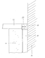
- the only figure is a schematic partial representation of an inventive shower partition.
- FIG. 10 It shows the upper right corner area of a shower partition according to the invention with a wall profile 10, a head profile 12 and a sliding element 14.
- the wall profile 10 is attached to a wall 16.
- a corner connector 18 At the top of the Wall profile 10 is a corner connector 18, in particular made of plastic.
- the wall profile 10 is, as usual, attached directly to the wall. It has one U-shaped, open to the left in Fig. 1 cross-section. Deviating from usual Constructions, the wall profile 10 contains no additional, U-shaped frame profile adjustable in the wall profile. Rather, the head profile 12 is direct connected to the wall profile 10 via the corner connector 18.
- This corner connector 18 can be on the upper end of the U-shaped wall profile put on and fastened here. He points one to the left in the drawing, So to the head profile 12 open guide pocket 20 in which the Head profile 12 is slidable. Even if the wall profile is due, for example a not exactly vertical wall 16 inclined to the right in the drawing would be, the head profile could be taken up by the guide pocket 20 become.
- the displaceability indicated by the double arrow in the drawing the head profile 12 in the guide pocket 20 allows an adjustment over a relatively large adjustment range.
- suitable Position the head profile 12 can finally with the help of devices, not shown, for example, a clamping screw.
- the head profile can also have a U-shaped cross section that is open at the bottom have, in which there is a running rail for the sliding element, this, as usual, the function of a door to enter the individual shower not shown met.
- the lower floor profile can be just like that Head profile 12 connected to the wall profile 10 via a corner connector 18 his.
- the wall profile 10 is a U-profile open towards the sliding element, this can Sliding element 14 in its right end position more or less in that Enter the wall profile so that the areas are covered and it is ensured that splash water cannot escape from the shower.
- the top and bottom profiles can be connected to the corner connectors can be determined without any preparatory work - drilling, screwing, etc. - being necessary are.
- the system according to the invention is particularly suitable for accommodation shower enclosures in recesses where the front End surface of the niche is taken up by sliding elements, however a fixed partition element can also be provided on at least one side his. This can also be immersed in the corresponding wall profile. For better Protection against the escape of splash water when showering can be between the partition element and the wall profile inserted a one-sided fuse become.
Landscapes
- Health & Medical Sciences (AREA)
- Public Health (AREA)
- Epidemiology (AREA)
- General Health & Medical Sciences (AREA)
- Bathtubs, Showers, And Their Attachments (AREA)
- Residential Or Office Buildings (AREA)
Abstract
Description
Claims (5)
- Duschabtrennung mit Wandanschluß, mit einem U-förmigen Wandprofil (10), einem Kopfprofil (12) und einem Bodenprofil sowie wenigstens einem in dem Kopf- und/oder Bodenprofil seitlich verschiebbar geführten Schiebeelement (14) oder festen Trennwandelement, dadurch gekennzeichnet, daß das Kopf- und das Bodenprofil unmittelbar mit dem Wandprofil (10) verbunden sind und daß am oberen und unteren Ende des Wandprofils (10) Eckverbinder (18) vorgesehen sind, die eine begrenzte Längsverstellung des Kopf- und Bodenprofils (12) zulassen.
- Duschabtrennung nach Anspruch 1, dadurch gekennzeichnet, daß die Eckverbinder (18) aus Kunststoff bestehen.
- Duschabtrennung nach Anspruch 1 oder 2, dadurch gekennzeichnet, daß die Eckverbinder (18) eine zu dem Kopf- und Bodenprofil hin offene Führungstasche (20) aufweist, in der das Kopf- und das Bodenprofil längs verschiebbar gehalten sind.
- Duschabtrennung nach einem der Ansprüche 1 bis 3, dadurch gekennzeichnet, daß zum Festlegen von Kopf- und Bodenprofil (12) in den Eckverbindern (18) Klemmschrauben vorgesehen sind.
- Duschabtrennung nach einem der Ansprüche 1 bis 4, bei der ein festes Trennwandelement in ein Wandprofil eintritt, dadurch gekennzeichnet, daß zwischen dem Wandprofil und dem festen Trennwandelement eine einseitig eingeschobene Dichtung vorgesehen ist.
Applications Claiming Priority (2)
| Application Number | Priority Date | Filing Date | Title |
|---|---|---|---|
| DE20009074U | 2000-05-19 | ||
| DE20009074U DE20009074U1 (de) | 2000-05-19 | 2000-05-19 | Duschabtrennung mit Wandanschluss |
Publications (1)
| Publication Number | Publication Date |
|---|---|
| EP1155648A1 true EP1155648A1 (de) | 2001-11-21 |
Family
ID=7941785
Family Applications (1)
| Application Number | Title | Priority Date | Filing Date |
|---|---|---|---|
| EP01111845A Withdrawn EP1155648A1 (de) | 2000-05-19 | 2001-05-16 | "Duschabtrennung mit Wandanschluss" |
Country Status (4)
| Country | Link |
|---|---|
| EP (1) | EP1155648A1 (de) |
| DE (1) | DE20009074U1 (de) |
| NO (1) | NO20012422L (de) |
| PL (1) | PL112195U1 (de) |
Citations (2)
| Publication number | Priority date | Publication date | Assignee | Title |
|---|---|---|---|---|
| DE2348376A1 (de) * | 1973-09-26 | 1975-04-10 | Roloff Heinz Rudolf | Eingangs- oder durchgangstuer, insbesondere fuer duschenabtrennungen |
| DE3800443A1 (de) * | 1988-01-09 | 1989-07-20 | Semer Gmbh & Co Kg W | Eckverbindung fuer die rahmenkonstruktion einer dusch- oder badewannenabtrennung u. dgl. |
-
2000
- 2000-05-19 DE DE20009074U patent/DE20009074U1/de not_active Expired - Lifetime
-
2001
- 2001-05-16 EP EP01111845A patent/EP1155648A1/de not_active Withdrawn
- 2001-05-16 NO NO20012422A patent/NO20012422L/no not_active Application Discontinuation
- 2001-05-18 PL PL11219501U patent/PL112195U1/xx unknown
Patent Citations (2)
| Publication number | Priority date | Publication date | Assignee | Title |
|---|---|---|---|---|
| DE2348376A1 (de) * | 1973-09-26 | 1975-04-10 | Roloff Heinz Rudolf | Eingangs- oder durchgangstuer, insbesondere fuer duschenabtrennungen |
| DE3800443A1 (de) * | 1988-01-09 | 1989-07-20 | Semer Gmbh & Co Kg W | Eckverbindung fuer die rahmenkonstruktion einer dusch- oder badewannenabtrennung u. dgl. |
Also Published As
| Publication number | Publication date |
|---|---|
| PL112195U1 (en) | 2001-12-03 |
| DE20009074U1 (de) | 2000-08-17 |
| NO20012422L (no) | 2001-11-20 |
| NO20012422D0 (no) | 2001-05-16 |
Similar Documents
| Publication | Publication Date | Title |
|---|---|---|
| DE19647723C1 (de) | Rahmengestell für einen Schaltschrank | |
| DE4439551C1 (de) | Rahmenschenkel für ein Rahmengestell eines Schaltschrankes | |
| DE19647814C2 (de) | Schaltschrank | |
| DE19647780C2 (de) | Rahmengestell mit einem Boden- und einem Deckrahmen aus einem Profilstrang | |
| EP1705335A2 (de) | Rolladenkastenabdeckung | |
| DE3443470A1 (de) | Fuehrungsschiene fuer rolladen | |
| DE3101947A1 (de) | Duschtrennwand | |
| DE2715238A1 (de) | Fenster- oder tuerrahmen | |
| DE2850779C2 (de) | Türzarge zur Führung von elektrischen Leitern | |
| DE19948468C2 (de) | Aufsatz-Rollladenkasten | |
| DE69302158T2 (de) | Profileinrichtung für die Verkabelung elektrischer Apparate, und geeignetes Skelett und Rinne um eine solche Einrichtung zu bauen | |
| CH702394A2 (de) | Schiebewand mit wenigstens zwei Flügeln. | |
| DE102005001622A1 (de) | Zargenvorrichtung für Öffnungen in Wänden | |
| DE69201253T2 (de) | Rolladen für Tür, Fenster oder dergleichen mit einer, mit einem Kasten versehenen, Modernisierungszarge. | |
| EP0812045A1 (de) | Kabelkanal für Gebäudeinnenräume | |
| CH624449A5 (en) | Device for connecting a covering frame to a base frame for windows, facades or room partitions | |
| DE20009074U1 (de) | Duschabtrennung mit Wandanschluss | |
| CH644667A5 (en) | Casing with window and/or door arranged in brickwork | |
| AT331011B (de) | Wandelement | |
| DE8902211U1 (de) | Vertikaler Rahmenholm einer Duschkabinen-Abtrennung | |
| DE60127324T2 (de) | Duschabtrennungseinheit | |
| DE8528320U1 (de) | Duschwand | |
| DE7906939U1 (de) | Laibungsverkleidung fuer wanddurchbrueche | |
| DE9400053U1 (de) | Abschlußprofil, insbesondere Türschwellenprofil | |
| DE3347734A1 (de) | Rolladenendstab mit den auslassschlitz im rolladenkasten abdichtender dichtung |
Legal Events
| Date | Code | Title | Description |
|---|---|---|---|
| PUAI | Public reference made under article 153(3) epc to a published international application that has entered the european phase |
Free format text: ORIGINAL CODE: 0009012 |
|
| AK | Designated contracting states |
Kind code of ref document: A1 Designated state(s): AT BE CH CY DE DK ES FI FR GB GR IE IT LI LU MC NL PT SE TR |
|
| AX | Request for extension of the european patent |
Free format text: AL;LT;LV;MK;RO;SI |
|
| 17P | Request for examination filed |
Effective date: 20020514 |
|
| AKX | Designation fees paid |
Free format text: AT BE CH CY DE DK ES FI FR GB GR IE IT LI LU MC NL PT SE TR |
|
| 17Q | First examination report despatched |
Effective date: 20021024 |
|
| GRAH | Despatch of communication of intention to grant a patent |
Free format text: ORIGINAL CODE: EPIDOS IGRA |
|
| STAA | Information on the status of an ep patent application or granted ep patent |
Free format text: STATUS: THE APPLICATION HAS BEEN WITHDRAWN |
|
| 18W | Application withdrawn |
Effective date: 20030823 |