EP1155185B1 - Procede et moyens pour la filtration de la pate a papier - Google Patents
Procede et moyens pour la filtration de la pate a papier Download PDFInfo
- Publication number
- EP1155185B1 EP1155185B1 EP00907721A EP00907721A EP1155185B1 EP 1155185 B1 EP1155185 B1 EP 1155185B1 EP 00907721 A EP00907721 A EP 00907721A EP 00907721 A EP00907721 A EP 00907721A EP 1155185 B1 EP1155185 B1 EP 1155185B1
- Authority
- EP
- European Patent Office
- Prior art keywords
- sieve
- filtration apparatus
- cavities
- scourer
- outlet
- Prior art date
- Legal status (The legal status is an assumption and is not a legal conclusion. Google has not performed a legal analysis and makes no representation as to the accuracy of the status listed.)
- Expired - Lifetime
Links
- 238000001914 filtration Methods 0.000 title claims abstract description 34
- 238000000034 method Methods 0.000 title claims abstract description 12
- 229920001131 Pulp (paper) Polymers 0.000 title claims abstract description 4
- 238000010790 dilution Methods 0.000 claims description 15
- 239000012895 dilution Substances 0.000 claims description 15
- 239000007788 liquid Substances 0.000 claims description 6
- 238000013019 agitation Methods 0.000 claims description 5
- 238000005189 flocculation Methods 0.000 abstract description 4
- 238000001935 peptisation Methods 0.000 abstract description 4
- 230000016615 flocculation Effects 0.000 abstract description 3
- 238000011001 backwashing Methods 0.000 abstract 2
- 238000005192 partition Methods 0.000 description 10
- 230000000694 effects Effects 0.000 description 6
- 239000000835 fiber Substances 0.000 description 5
- 230000008719 thickening Effects 0.000 description 4
- XLYOFNOQVPJJNP-UHFFFAOYSA-N water Substances O XLYOFNOQVPJJNP-UHFFFAOYSA-N 0.000 description 4
- 235000021183 entrée Nutrition 0.000 description 3
- 239000011888 foil Substances 0.000 description 3
- 230000010349 pulsation Effects 0.000 description 3
- 238000003756 stirring Methods 0.000 description 3
- 230000003416 augmentation Effects 0.000 description 2
- 238000005243 fluidization Methods 0.000 description 2
- 241000940835 Pales Species 0.000 description 1
- 206010033546 Pallor Diseases 0.000 description 1
- 238000009825 accumulation Methods 0.000 description 1
- 238000005265 energy consumption Methods 0.000 description 1
- 238000005516 engineering process Methods 0.000 description 1
- 244000144992 flock Species 0.000 description 1
- 238000004519 manufacturing process Methods 0.000 description 1
- 238000003801 milling Methods 0.000 description 1
- 230000000750 progressive effect Effects 0.000 description 1
- 238000004537 pulping Methods 0.000 description 1
- 238000005086 pumping Methods 0.000 description 1
- 238000011144 upstream manufacturing Methods 0.000 description 1
Images


Classifications
-
- D—TEXTILES; PAPER
- D21—PAPER-MAKING; PRODUCTION OF CELLULOSE
- D21D—TREATMENT OF THE MATERIALS BEFORE PASSING TO THE PAPER-MAKING MACHINE
- D21D5/00—Purification of the pulp suspension by mechanical means; Apparatus therefor
- D21D5/02—Straining or screening the pulp
- D21D5/023—Stationary screen-drums
- D21D5/026—Stationary screen-drums with rotating cleaning foils
Definitions
- the present invention relates to the problems of pulp filtration at paper and more particularly pulp from pulping old papers.
- filters comprising a rotor and a stator, one of two, hereinafter referred to as sieves fulfilling the function of filtering with holes such as slots or holes, the other below called decolator, fulfilling the declogging function with means for generating pressure pulsations to prevent clogging holes.
- the sieve can therefore be fixed or rotating and, conversely, the decolator is rotating with a fixed sieve and fixed with a rotating sieve. Of the more the liquid can either flow through the sieve from the outside to the inside (towards the axis), so-called centripetal operation, either from the inside to the outside, said centrifugal operation.
- the dough arrives at one end of the cylindrical sieve, flows in the space between the cylindrical sieve and the decolator, and spring at the other end.
- the decolator turns, it tends to drive the dough with him in rotation. If the decolator is fixed, it is the filter that tends to cause the dough in rotation. In both cases, as the effect of declogging by the pulsations of pressure caused by the decolator is directly related to the speed difference between the decolator and the dough, the dough progresses towards the end of the sieve, less unclogging is effective and this while the sieve is more likely to seal.
- the present invention relates to a filtration apparatus of the type comprising a cylindrical sieve and a decolator equipped with blades that produce pressure fluctuations to fight against the clogging of said sieve, the latter being in at least two parts of substantially equal diameter from each other by means intended to break the component of the velocity of the liquid, which is parallel to the surface of the sieve and to create turbulence, characterized in that said means are baffles formed on the one hand by cavities formed in an annular ring of the sieve disposed between said sieve parts and secondly by a deflector annular carried by the decolator in front of each crown of the sieve bearing the cavities, so that the majority of the liquid flow is forced to cross the cavities.
- the present invention also provides a method of using this apparatus for the treatment of paper pulp according to which each part of the apparatus of filtration includes an output of accepted products and each annular ring of the sieve optionally has a dilution inlet the filtration apparatus further comprising an input and an output of the rejects, and according to which by playing on the settings of the accepted product exits, the release of the rejects and the arrivals dilution of the pipes reduces the rotation speed of the decolator so that it is as low as possible in order to save energy, while maintaining a low discharge rate.
- the present invention also aims at the implementation of the above means described for filtering pulp.
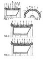
- the sieve is constituted, as has been described in patent EP 0 707 109 by a stack of circles 1 with U section, pressed against each other by means of two end crowns 2 and 3 assembled to each other by tie rods 4 which make it possible to establish a prestressing.
- the bases of the U are provided with holes (whether they are slots or holes).
- the dough arrives in the filter by its end to the left of the figure (on the side of the crown 2) and emerges by its opposite end (on the side of the 3) circulating in the space 6 located between the decolator 5 and the sieve as indicated by the arrow f1.
- a slowdown zone is created for the speed at which the dough is driven.
- an annular partition 21 perpendicular to the filter axis and carried by the rotor 5.
- Fluidization is understood to mean a stirred and floc-free state of the dough which favors the flow in the openings, holes or slots of the sieve.
- the sieve is divided into two parts; a first part in upstream of the crown of cavities C and a second part downstream, these two parts being separated from each other by the crown of cavities C.
- the baffle 20/21 is disposed in the middle of the sieve; in Figure 3 it is arranged near the end, that is to say where the effects of clogging are the most important because of the thickening of the dough.
- Figure 4 combines the provisions of Figures 1 and 3.
- turbulence is also created by fins 10 fixed to the decolator and fins 11 fixed on the screen.
- These fins 10 and 11 may be radial or inclined and may have inclinations in the opposite direction.
- fins 10/11 are such that they fit into each other.
- FIG. 6 represents a centripetal filter that uses the means of FIG. 1. The same elements bear the same references.
- the sieve 1 is inside the decolator 5.
- the dough arrives at the end of the sieve and circulates in the space 6 located between the sieve 1 and the decolator 5.
- the U-section circles are replaced by partitions 20, parallel to the axis of the cylinder, and the decolator 5 comprises a annular partition 21.
- the paste is deflected by the annular partition 21 and hits the partitions 20.
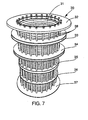
- Figures 7 to 17 show an alternative embodiment of the apparatus implementing the method according to the present invention.
- FIG. 7 represents a cylindrical sieve 30 which consists of bars 31 arranged vertically next to each other with a slight clearance (included between 0.05 mm and 1 mm) and fixed on horizontal rings 32, 33, 34, 35, 36 and 37.
- FIG. 8 shows the rotor 40 which is placed inside the sieve of the FIG. 7.
- This rotor is a cylinder which comprises three annular rings 41, 42, and 43. In the areas between the ring rings are arranged blades 45, commonly referred to as "foils" in the pulp industry.
- the function of the foils 45 is to cause pulsations of pressure / depression which tend to prevent clogging of the sieve.
- the rings 41 to 43 are arranged on the rotor so as to be opposite crowns 33, 34 and 35.
- the annular rings 41, 42 and 43 define four zones of the rotor 40.
- the shape, number and inclination of the blades or foils 45 may vary from one area to another.
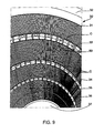
- Figure 9 shows the screen of Figure 7 seen from the inside.
- crowns 33, 34 and 35 are hollow so as to define cavities C.
- the cavities C are not made as in the case of Figures 1 to 6 where the sieve was constituted by U.
- the rings 33, 34, 35 are constituted by a ring comprising a multitude of parallelepiped cavities having practically the same shape as the cavities C of Figures 1 to 6.
- Some cavities C crowns 33 and / or 34 further comprise orifices which are connected to dilution inlet pipes 50.
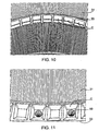
- Figures 10 and 11 are detail views, on a larger scale of the figure 9.
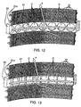
- Figure 12 illustrates a variant according to which, instead of having parallelepiped cavities C cylindrical cavities or blind holes are available Some may be connected to conduits 50.
- the annular ring of the rotor 41 (42,43) which cooperates with the ring 33 (34, 35) is arranged to be substantially at the middle of the cavities C or cylindrical holes D.
- Arrow F illustrates how dough from the area below crowns 33, 41 is forced into a cavity C or D, this cavity and the crown 41 forming a baffle that significantly slows the speed of the dough.
- FIG. 14 illustrates another variant embodiment in which the same elements bear the same references.
- the screen 30 is fixed and placed outside the rotor 40 which 45.
- the ring 41 of the rotor 40 is in front of the ring 33 of the sieve 30 so that the cavities C of said ring 33 form with the annular ring 41 a series of baffles.
- a pipe 50 which is a water pipe.
- the filter element constituted by the screen 30 and the rotor 40 is thus divided in three areas X, Y and Z from the bottom.
- the pulp to be purified arrives at Q at the base of the device.
- Zone X has an output 60 for the so-called "accepted” products, that is to say who passed through the sieve 30; zone Y has an output 61 for Accepted products and Zone Z an exit 62 for accepted products.
- thickening causes a decrease in the efficiency of the declogging which must be compensated for example by a higher speed and therefore a higher energy consumption.
- the introduction of water into ducts 50 which open into certain cavities C or D of the crown 34 and the ring 33 makes it possible to counter this thickening and thus makes it possible to reduce the rotor speed and thus save energy.
- the apparatus comprises a cover 63, an output R for the rejects.
- the speed of the rotor 40 can be adjusted according to the pressure differential between the entry Q in the apparatus and at least one of the pressures prevailing in the outlet ducts of accepted products 60, 61, 62.
- the sieve can be made in many ways either by stacking rings to U-section of Figures 1 to 6, either by stacking grids obtained by juxtaposition of bars of Figures 12 and 13, or by stacking the sheets perforated cylindrical holes or slits of Figure 15.
- they may be constituted by plates 70, in the mass of which were hollowed with circular milling grooves 71, the slots are then machined with circular saws.
- the rotor 40 being divided into as many portions as the sieve 30 can at each portion of the rotor have different blades 45 as to their number, their form, and their inclination.
- edges of the cavities C or D are exactly at the same level as that of the inner wall of the sieve 30.
Landscapes
- Engineering & Computer Science (AREA)
- Mechanical Engineering (AREA)
- Paper (AREA)
- Filtering Materials (AREA)
- Centrifugal Separators (AREA)
- Combined Means For Separation Of Solids (AREA)
- Electrical Discharge Machining, Electrochemical Machining, And Combined Machining (AREA)
- Separation Of Solids By Using Liquids Or Pneumatic Power (AREA)
Applications Claiming Priority (3)
| Application Number | Priority Date | Filing Date | Title |
|---|---|---|---|
| FR9902425 | 1999-02-26 | ||
| FR9902425A FR2790270B1 (fr) | 1999-02-26 | 1999-02-26 | Procedes et moyens pour la filtration de la pate a papier |
| PCT/FR2000/000468 WO2000050690A1 (fr) | 1999-02-26 | 2000-02-25 | Procede et moyens pour la filtration de la pate a papier |
Publications (2)
| Publication Number | Publication Date |
|---|---|
| EP1155185A1 EP1155185A1 (fr) | 2001-11-21 |
| EP1155185B1 true EP1155185B1 (fr) | 2004-04-14 |
Family
ID=9542587
Family Applications (1)
| Application Number | Title | Priority Date | Filing Date |
|---|---|---|---|
| EP00907721A Expired - Lifetime EP1155185B1 (fr) | 1999-02-26 | 2000-02-25 | Procede et moyens pour la filtration de la pate a papier |
Country Status (12)
| Country | Link |
|---|---|
| US (1) | US6679384B1 (enExample) |
| EP (1) | EP1155185B1 (enExample) |
| JP (1) | JP4530545B2 (enExample) |
| AT (1) | ATE264425T1 (enExample) |
| AU (1) | AU2921400A (enExample) |
| BR (1) | BR0007868B1 (enExample) |
| CA (1) | CA2362500C (enExample) |
| DE (1) | DE60009869T2 (enExample) |
| ES (1) | ES2218131T3 (enExample) |
| FR (1) | FR2790270B1 (enExample) |
| NO (1) | NO317608B1 (enExample) |
| WO (1) | WO2000050690A1 (enExample) |
Cited By (1)
| Publication number | Priority date | Publication date | Assignee | Title |
|---|---|---|---|---|
| US7491296B2 (en) | 2002-06-07 | 2009-02-17 | Metso Paper, Inc. | Multi-stage screening apparatus, screen basket and method for screening pulp suspensions |
Families Citing this family (14)
| Publication number | Priority date | Publication date | Assignee | Title |
|---|---|---|---|---|
| JP4015527B2 (ja) | 2002-10-16 | 2007-11-28 | 相川鉄工株式会社 | スクリ−ン装置 |
| AT413391B (de) * | 2003-03-27 | 2006-02-15 | Andritz Ag Maschf | Sortierer zur reinigung einer fasersuspension |
| AT413390B (de) * | 2003-03-27 | 2006-02-15 | Andritz Ag Maschf | Sortierer zur reinigung einer fasersuspension |
| SE526033C3 (sv) * | 2003-11-06 | 2009-12-08 | Metso Paper Inc | Silanordning och silkorg för silning av massasuspensioner |
| JP2005171449A (ja) * | 2003-12-15 | 2005-06-30 | Aikawa Iron Works Co Ltd | 製紙用スクリ−ン装置 |
| US7393446B2 (en) * | 2004-03-05 | 2008-07-01 | Frank E. Towsley | Cellular metal structure |
| DE102004031622B4 (de) * | 2004-06-30 | 2006-06-14 | Voith Paper Patent Gmbh | Drucksortierer zum Sieben einer Faserstoffsuspension |
| JP2006089884A (ja) * | 2004-09-27 | 2006-04-06 | Aikawa Iron Works Co Ltd | スクリーン装置 |
| JP4909693B2 (ja) * | 2006-07-24 | 2012-04-04 | 相川鉄工株式会社 | スクリーン装置 |
| EP2547824B1 (en) | 2010-03-16 | 2018-07-18 | Tampulping OY | Pressure filter |
| DE102010032350A1 (de) * | 2010-07-27 | 2012-02-02 | Automatic Plastics Machinery Gmbh | Vorrichtung zur Trocknung von Granulatkörnern |
| CN113215848B (zh) * | 2021-04-30 | 2023-05-26 | 安德里茨(中国)有限公司 | 压力筛和用于压力筛的稀释方法 |
| CN116531818A (zh) * | 2023-05-16 | 2023-08-04 | 中国安能集团第一工程局有限公司 | 施工地下水处理装置 |
| CN119952880B (zh) * | 2025-03-25 | 2025-09-12 | 苏州贝克莱塑料有限公司 | 一种塑料废料回收利用装置 |
Family Cites Families (13)
| Publication number | Priority date | Publication date | Assignee | Title |
|---|---|---|---|---|
| DE558447C (de) * | 1932-09-09 | J M Voith Fa | Schleudersichter fuer Holzschliff, Zellstoff u. dgl. mit liegender Fluegelwelle | |
| US1537691A (en) * | 1923-08-16 | 1925-05-12 | American Voith Contact Co | Centrifugal screen |
| DE558477C (de) | 1931-09-18 | 1932-09-07 | Frey & Co W | Blankgluehofen fuer Draehte u. dgl. |
| JPS61153114A (ja) * | 1984-12-25 | 1986-07-11 | Mitsubishi Heavy Ind Ltd | ふるい分け装置 |
| FR2613390B1 (fr) * | 1987-04-06 | 1995-01-20 | Lamort Sa E M | Perfectionnement aux tamis employes pour le traitement de la pate a papier |
| FI77279C (fi) * | 1987-04-30 | 1989-02-10 | Ahlstroem Oy | Foerfarande och anordning foer behandling av fibersuspension. |
| DE3831845A1 (de) * | 1988-09-19 | 1990-04-12 | Voith Gmbh J M | Sortiereinrichtung fuer fasersuspensionen |
| SU1669585A1 (ru) * | 1989-04-26 | 1991-08-15 | Воронежский сельскохозяйственный институт им.К.Д.Глинки | Центробежный сепаратор |
| FI84191C (fi) * | 1989-05-17 | 1992-11-25 | Ahlstroem Oy | Foerfarande och anordning foer behandling av fibersuspension |
| US5096127A (en) * | 1990-08-22 | 1992-03-17 | Ingersoll-Rand Company | Apparatus for pressurized screening of a fibrous material liquid suspension |
| FR2666598B1 (fr) * | 1990-09-10 | 1994-05-27 | Escher Wyss Gmbh | Procede de separation, notamment de tri ou de fractionnement d'une suspension de pate a papier. |
| SE507481C2 (sv) * | 1996-05-02 | 1998-06-15 | Alfa Laval Ab | Anordning för separering av föroreningar från fibermassasuspensioner |
| US6155427A (en) * | 1996-11-14 | 2000-12-05 | Thermo Black Clawson Inc. | Zoned pressure screen |
-
1999
- 1999-02-26 FR FR9902425A patent/FR2790270B1/fr not_active Expired - Lifetime
-
2000
- 2000-02-25 DE DE60009869T patent/DE60009869T2/de not_active Expired - Lifetime
- 2000-02-25 AT AT00907721T patent/ATE264425T1/de active
- 2000-02-25 ES ES00907721T patent/ES2218131T3/es not_active Expired - Lifetime
- 2000-02-25 AU AU29214/00A patent/AU2921400A/en not_active Abandoned
- 2000-02-25 BR BRPI0007868-9A patent/BR0007868B1/pt not_active IP Right Cessation
- 2000-02-25 CA CA002362500A patent/CA2362500C/fr not_active Expired - Fee Related
- 2000-02-25 WO PCT/FR2000/000468 patent/WO2000050690A1/fr not_active Ceased
- 2000-02-25 EP EP00907721A patent/EP1155185B1/fr not_active Expired - Lifetime
- 2000-02-25 JP JP2000601244A patent/JP4530545B2/ja not_active Expired - Fee Related
- 2000-02-25 US US09/890,787 patent/US6679384B1/en not_active Expired - Lifetime
-
2001
- 2001-08-24 NO NO20014132A patent/NO317608B1/no not_active IP Right Cessation
Cited By (1)
| Publication number | Priority date | Publication date | Assignee | Title |
|---|---|---|---|---|
| US7491296B2 (en) | 2002-06-07 | 2009-02-17 | Metso Paper, Inc. | Multi-stage screening apparatus, screen basket and method for screening pulp suspensions |
Also Published As
| Publication number | Publication date |
|---|---|
| AU2921400A (en) | 2000-09-14 |
| BR0007868A (pt) | 2001-10-16 |
| FR2790270B1 (fr) | 2001-11-16 |
| ES2218131T3 (es) | 2004-11-16 |
| NO317608B1 (no) | 2004-11-22 |
| NO20014132L (no) | 2001-10-12 |
| DE60009869D1 (de) | 2004-05-19 |
| FR2790270A1 (fr) | 2000-09-01 |
| CA2362500C (fr) | 2007-08-21 |
| US6679384B1 (en) | 2004-01-20 |
| CA2362500A1 (fr) | 2000-08-31 |
| NO20014132D0 (no) | 2001-08-24 |
| EP1155185A1 (fr) | 2001-11-21 |
| BR0007868B1 (pt) | 2010-04-06 |
| JP2002537964A (ja) | 2002-11-12 |
| WO2000050690A1 (fr) | 2000-08-31 |
| DE60009869T2 (de) | 2005-04-21 |
| ATE264425T1 (de) | 2004-04-15 |
| JP4530545B2 (ja) | 2010-08-25 |
Similar Documents
| Publication | Publication Date | Title |
|---|---|---|
| EP1155185B1 (fr) | Procede et moyens pour la filtration de la pate a papier | |
| CA2671216C (fr) | Dispositif de separation de particules solides et installation hydraulique comprenant un tel dispositif | |
| CH637029A5 (fr) | Dispositif rotatif de filtrage de pulpe. | |
| FR2645184A1 (fr) | Appareil de fluidisation, de degazage et de pompage d'une suspension d'une matiere cellulosique fibreuse | |
| FR2578177A1 (fr) | Dispositif de criblage. | |
| FR2538715A1 (fr) | Dispositif epurateur d'air, notamment pour moteurs a combustion interne | |
| EP0303655B1 (fr) | Turbine centrifuge a action | |
| EP0198737B1 (fr) | Appareil de décontamination de pâte à papier | |
| EP0104966B1 (fr) | Centrifugeuse à récupération d'énergie | |
| FR2617516A1 (fr) | Appareil de repartition d'une pate cellulosique fibreuse | |
| FR2478694A1 (fr) | Trieuse a disques pour l'epuration de suspensions de matieres fibreuses | |
| FR2476164A1 (fr) | Cellule de flottaison tubulaire | |
| EP1907091B1 (fr) | Dispositif de separation gravitaire pour le traitement des eaux | |
| FR2643396A1 (fr) | Appareil pour filtrer une suspension de matiere cellulosique fibreuse | |
| FR2663240A1 (fr) | Appareil pour la separation d'un liquide et des particules solides en suspension qu'il contient. | |
| EP0286535B1 (fr) | Perfectionnement aux tamis pour épurateurs de pâte à papier | |
| EP0629738A1 (fr) | Rotor pour l'épuration hydrodynamique sous pression de pâte à papier, et appareil muni de ce rotor | |
| FR2632332A1 (fr) | Appareil de separation pour suspension de pate cellulosique fibreuse | |
| CH659001A5 (fr) | Tamis rotatif. | |
| JP3595544B2 (ja) | 紙料分離精選装置 | |
| FR2699089A1 (fr) | Dispositif de filtrage auto-nettoyant pour fluides renfermant des particules solides. | |
| EP2181748B1 (fr) | Séparateur hydrodynamique pour nettoyer une veine de fluide | |
| EP0249668B1 (fr) | Appareil pour la séparation centrifuge d'un mélange de phases | |
| FR2464329A1 (fr) | Dispositif de filtration pour l'epaississement de suspensions fibreuses | |
| CH651765A5 (fr) | Appareil de separation centrifuge applicable notamment a l'epuration des melanges gazeux. |
Legal Events
| Date | Code | Title | Description |
|---|---|---|---|
| PUAI | Public reference made under article 153(3) epc to a published international application that has entered the european phase |
Free format text: ORIGINAL CODE: 0009012 |
|
| 17P | Request for examination filed |
Effective date: 20010712 |
|
| AK | Designated contracting states |
Kind code of ref document: A1 Designated state(s): AT BE CH CY DE DK ES FI FR GB GR IE IT LI LU MC NL PT SE |
|
| GRAP | Despatch of communication of intention to grant a patent |
Free format text: ORIGINAL CODE: EPIDOSNIGR1 |
|
| RAP1 | Party data changed (applicant data changed or rights of an application transferred) |
Owner name: KADANT LAMORT |
|
| GRAS | Grant fee paid |
Free format text: ORIGINAL CODE: EPIDOSNIGR3 |
|
| GRAA | (expected) grant |
Free format text: ORIGINAL CODE: 0009210 |
|
| AK | Designated contracting states |
Kind code of ref document: B1 Designated state(s): AT BE CH CY DE DK ES FI FR GB GR IE IT LI LU MC NL PT SE |
|
| PG25 | Lapsed in a contracting state [announced via postgrant information from national office to epo] |
Ref country code: IE Free format text: LAPSE BECAUSE OF FAILURE TO SUBMIT A TRANSLATION OF THE DESCRIPTION OR TO PAY THE FEE WITHIN THE PRESCRIBED TIME-LIMIT Effective date: 20040414 Ref country code: NL Free format text: LAPSE BECAUSE OF FAILURE TO SUBMIT A TRANSLATION OF THE DESCRIPTION OR TO PAY THE FEE WITHIN THE PRESCRIBED TIME-LIMIT Effective date: 20040414 |
|
| REG | Reference to a national code |
Ref country code: GB Ref legal event code: FG4D Free format text: NOT ENGLISH |
|
| REG | Reference to a national code |
Ref country code: CH Ref legal event code: EP |
|
| GBT | Gb: translation of ep patent filed (gb section 77(6)(a)/1977) |
Effective date: 20040414 |
|
| REF | Corresponds to: |
Ref document number: 60009869 Country of ref document: DE Date of ref document: 20040519 Kind code of ref document: P |
|
| REG | Reference to a national code |
Ref country code: IE Ref legal event code: FG4D Free format text: FRENCH |
|
| PG25 | Lapsed in a contracting state [announced via postgrant information from national office to epo] |
Ref country code: GR Free format text: LAPSE BECAUSE OF FAILURE TO SUBMIT A TRANSLATION OF THE DESCRIPTION OR TO PAY THE FEE WITHIN THE PRESCRIBED TIME-LIMIT Effective date: 20040714 Ref country code: DK Free format text: LAPSE BECAUSE OF FAILURE TO SUBMIT A TRANSLATION OF THE DESCRIPTION OR TO PAY THE FEE WITHIN THE PRESCRIBED TIME-LIMIT Effective date: 20040714 |
|
| REG | Reference to a national code |
Ref country code: SE Ref legal event code: TRGR |
|
| NLV1 | Nl: lapsed or annulled due to failure to fulfill the requirements of art. 29p and 29m of the patents act | ||
| REG | Reference to a national code |
Ref country code: ES Ref legal event code: FG2A Ref document number: 2218131 Country of ref document: ES Kind code of ref document: T3 |
|
| REG | Reference to a national code |
Ref country code: IE Ref legal event code: FD4D |
|
| PLBE | No opposition filed within time limit |
Free format text: ORIGINAL CODE: 0009261 |
|
| STAA | Information on the status of an ep patent application or granted ep patent |
Free format text: STATUS: NO OPPOSITION FILED WITHIN TIME LIMIT |
|
| PG25 | Lapsed in a contracting state [announced via postgrant information from national office to epo] |
Ref country code: CY Free format text: LAPSE BECAUSE OF FAILURE TO SUBMIT A TRANSLATION OF THE DESCRIPTION OR TO PAY THE FEE WITHIN THE PRESCRIBED TIME-LIMIT Effective date: 20050225 Ref country code: LU Free format text: LAPSE BECAUSE OF NON-PAYMENT OF DUE FEES Effective date: 20050225 |
|
| PG25 | Lapsed in a contracting state [announced via postgrant information from national office to epo] |
Ref country code: BE Free format text: LAPSE BECAUSE OF NON-PAYMENT OF DUE FEES Effective date: 20050228 Ref country code: LI Free format text: LAPSE BECAUSE OF NON-PAYMENT OF DUE FEES Effective date: 20050228 Ref country code: CH Free format text: LAPSE BECAUSE OF NON-PAYMENT OF DUE FEES Effective date: 20050228 Ref country code: MC Free format text: LAPSE BECAUSE OF NON-PAYMENT OF DUE FEES Effective date: 20050228 |
|
| 26N | No opposition filed |
Effective date: 20050117 |
|
| BERE | Be: lapsed |
Owner name: *KADANT LAMORT Effective date: 20050228 |
|
| REG | Reference to a national code |
Ref country code: CH Ref legal event code: PL |
|
| BERE | Be: lapsed |
Owner name: *KADANT LAMORT Effective date: 20050228 |
|
| PG25 | Lapsed in a contracting state [announced via postgrant information from national office to epo] |
Ref country code: PT Free format text: LAPSE BECAUSE OF NON-PAYMENT OF DUE FEES Effective date: 20040914 |
|
| PGFP | Annual fee paid to national office [announced via postgrant information from national office to epo] |
Ref country code: GB Payment date: 20130218 Year of fee payment: 14 Ref country code: ES Payment date: 20130227 Year of fee payment: 14 |
|
| GBPC | Gb: european patent ceased through non-payment of renewal fee |
Effective date: 20140225 |
|
| PG25 | Lapsed in a contracting state [announced via postgrant information from national office to epo] |
Ref country code: GB Free format text: LAPSE BECAUSE OF NON-PAYMENT OF DUE FEES Effective date: 20140225 |
|
| REG | Reference to a national code |
Ref country code: ES Ref legal event code: FD2A Effective date: 20150506 |
|
| PG25 | Lapsed in a contracting state [announced via postgrant information from national office to epo] |
Ref country code: ES Free format text: LAPSE BECAUSE OF NON-PAYMENT OF DUE FEES Effective date: 20140226 |
|
| REG | Reference to a national code |
Ref country code: FR Ref legal event code: PLFP Year of fee payment: 17 |
|
| REG | Reference to a national code |
Ref country code: FR Ref legal event code: PLFP Year of fee payment: 18 |
|
| REG | Reference to a national code |
Ref country code: FR Ref legal event code: PLFP Year of fee payment: 19 |
|
| PGFP | Annual fee paid to national office [announced via postgrant information from national office to epo] |
Ref country code: DE Payment date: 20180219 Year of fee payment: 19 Ref country code: FI Payment date: 20180219 Year of fee payment: 19 |
|
| PGFP | Annual fee paid to national office [announced via postgrant information from national office to epo] |
Ref country code: AT Payment date: 20180219 Year of fee payment: 19 Ref country code: IT Payment date: 20180227 Year of fee payment: 19 Ref country code: FR Payment date: 20180226 Year of fee payment: 19 Ref country code: SE Payment date: 20180227 Year of fee payment: 19 |
|
| REG | Reference to a national code |
Ref country code: DE Ref legal event code: R119 Ref document number: 60009869 Country of ref document: DE |
|
| REG | Reference to a national code |
Ref country code: SE Ref legal event code: EUG |
|
| REG | Reference to a national code |
Ref country code: AT Ref legal event code: MM01 Ref document number: 264425 Country of ref document: AT Kind code of ref document: T Effective date: 20190225 |
|
| PG25 | Lapsed in a contracting state [announced via postgrant information from national office to epo] |
Ref country code: FI Free format text: LAPSE BECAUSE OF NON-PAYMENT OF DUE FEES Effective date: 20190225 Ref country code: SE Free format text: LAPSE BECAUSE OF NON-PAYMENT OF DUE FEES Effective date: 20190226 |
|
| PG25 | Lapsed in a contracting state [announced via postgrant information from national office to epo] |
Ref country code: AT Free format text: LAPSE BECAUSE OF NON-PAYMENT OF DUE FEES Effective date: 20190225 |
|
| PG25 | Lapsed in a contracting state [announced via postgrant information from national office to epo] |
Ref country code: DE Free format text: LAPSE BECAUSE OF NON-PAYMENT OF DUE FEES Effective date: 20190903 |
|
| PG25 | Lapsed in a contracting state [announced via postgrant information from national office to epo] |
Ref country code: FR Free format text: LAPSE BECAUSE OF NON-PAYMENT OF DUE FEES Effective date: 20190228 Ref country code: IT Free format text: LAPSE BECAUSE OF NON-PAYMENT OF DUE FEES Effective date: 20190225 |