EP1155185B1 - Method and means for paper pulp filtering - Google Patents
Method and means for paper pulp filtering Download PDFInfo
- Publication number
- EP1155185B1 EP1155185B1 EP00907721A EP00907721A EP1155185B1 EP 1155185 B1 EP1155185 B1 EP 1155185B1 EP 00907721 A EP00907721 A EP 00907721A EP 00907721 A EP00907721 A EP 00907721A EP 1155185 B1 EP1155185 B1 EP 1155185B1
- Authority
- EP
- European Patent Office
- Prior art keywords
- sieve
- filtration apparatus
- cavities
- scourer
- outlet
- Prior art date
- Legal status (The legal status is an assumption and is not a legal conclusion. Google has not performed a legal analysis and makes no representation as to the accuracy of the status listed.)
- Expired - Lifetime
Links
Images


Classifications
-
- D—TEXTILES; PAPER
- D21—PAPER-MAKING; PRODUCTION OF CELLULOSE
- D21D—TREATMENT OF THE MATERIALS BEFORE PASSING TO THE PAPER-MAKING MACHINE
- D21D5/00—Purification of the pulp suspension by mechanical means; Apparatus therefor
- D21D5/02—Straining or screening the pulp
- D21D5/023—Stationary screen-drums
- D21D5/026—Stationary screen-drums with rotating cleaning foils
Definitions
- the present invention relates to the problems of pulp filtration at paper and more particularly pulp from pulping old papers.
- filters comprising a rotor and a stator, one of two, hereinafter referred to as sieves fulfilling the function of filtering with holes such as slots or holes, the other below called decolator, fulfilling the declogging function with means for generating pressure pulsations to prevent clogging holes.
- the sieve can therefore be fixed or rotating and, conversely, the decolator is rotating with a fixed sieve and fixed with a rotating sieve. Of the more the liquid can either flow through the sieve from the outside to the inside (towards the axis), so-called centripetal operation, either from the inside to the outside, said centrifugal operation.
- the dough arrives at one end of the cylindrical sieve, flows in the space between the cylindrical sieve and the decolator, and spring at the other end.
- the decolator turns, it tends to drive the dough with him in rotation. If the decolator is fixed, it is the filter that tends to cause the dough in rotation. In both cases, as the effect of declogging by the pulsations of pressure caused by the decolator is directly related to the speed difference between the decolator and the dough, the dough progresses towards the end of the sieve, less unclogging is effective and this while the sieve is more likely to seal.
- the present invention relates to a filtration apparatus of the type comprising a cylindrical sieve and a decolator equipped with blades that produce pressure fluctuations to fight against the clogging of said sieve, the latter being in at least two parts of substantially equal diameter from each other by means intended to break the component of the velocity of the liquid, which is parallel to the surface of the sieve and to create turbulence, characterized in that said means are baffles formed on the one hand by cavities formed in an annular ring of the sieve disposed between said sieve parts and secondly by a deflector annular carried by the decolator in front of each crown of the sieve bearing the cavities, so that the majority of the liquid flow is forced to cross the cavities.
- the present invention also provides a method of using this apparatus for the treatment of paper pulp according to which each part of the apparatus of filtration includes an output of accepted products and each annular ring of the sieve optionally has a dilution inlet the filtration apparatus further comprising an input and an output of the rejects, and according to which by playing on the settings of the accepted product exits, the release of the rejects and the arrivals dilution of the pipes reduces the rotation speed of the decolator so that it is as low as possible in order to save energy, while maintaining a low discharge rate.
- the present invention also aims at the implementation of the above means described for filtering pulp.
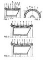
- the sieve is constituted, as has been described in patent EP 0 707 109 by a stack of circles 1 with U section, pressed against each other by means of two end crowns 2 and 3 assembled to each other by tie rods 4 which make it possible to establish a prestressing.
- the bases of the U are provided with holes (whether they are slots or holes).
- the dough arrives in the filter by its end to the left of the figure (on the side of the crown 2) and emerges by its opposite end (on the side of the 3) circulating in the space 6 located between the decolator 5 and the sieve as indicated by the arrow f1.
- a slowdown zone is created for the speed at which the dough is driven.
- an annular partition 21 perpendicular to the filter axis and carried by the rotor 5.
- Fluidization is understood to mean a stirred and floc-free state of the dough which favors the flow in the openings, holes or slots of the sieve.
- the sieve is divided into two parts; a first part in upstream of the crown of cavities C and a second part downstream, these two parts being separated from each other by the crown of cavities C.
- the baffle 20/21 is disposed in the middle of the sieve; in Figure 3 it is arranged near the end, that is to say where the effects of clogging are the most important because of the thickening of the dough.
- Figure 4 combines the provisions of Figures 1 and 3.
- turbulence is also created by fins 10 fixed to the decolator and fins 11 fixed on the screen.
- These fins 10 and 11 may be radial or inclined and may have inclinations in the opposite direction.
- fins 10/11 are such that they fit into each other.
- FIG. 6 represents a centripetal filter that uses the means of FIG. 1. The same elements bear the same references.
- the sieve 1 is inside the decolator 5.
- the dough arrives at the end of the sieve and circulates in the space 6 located between the sieve 1 and the decolator 5.
- the U-section circles are replaced by partitions 20, parallel to the axis of the cylinder, and the decolator 5 comprises a annular partition 21.
- the paste is deflected by the annular partition 21 and hits the partitions 20.
- Figures 7 to 17 show an alternative embodiment of the apparatus implementing the method according to the present invention.
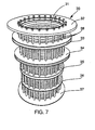
- FIG. 7 represents a cylindrical sieve 30 which consists of bars 31 arranged vertically next to each other with a slight clearance (included between 0.05 mm and 1 mm) and fixed on horizontal rings 32, 33, 34, 35, 36 and 37.
- FIG. 8 shows the rotor 40 which is placed inside the sieve of the FIG. 7.
- This rotor is a cylinder which comprises three annular rings 41, 42, and 43. In the areas between the ring rings are arranged blades 45, commonly referred to as "foils" in the pulp industry.
- the function of the foils 45 is to cause pulsations of pressure / depression which tend to prevent clogging of the sieve.
- the rings 41 to 43 are arranged on the rotor so as to be opposite crowns 33, 34 and 35.
- the annular rings 41, 42 and 43 define four zones of the rotor 40.
- the shape, number and inclination of the blades or foils 45 may vary from one area to another.
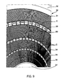
- Figure 9 shows the screen of Figure 7 seen from the inside.
- crowns 33, 34 and 35 are hollow so as to define cavities C.
- the cavities C are not made as in the case of Figures 1 to 6 where the sieve was constituted by U.
- the rings 33, 34, 35 are constituted by a ring comprising a multitude of parallelepiped cavities having practically the same shape as the cavities C of Figures 1 to 6.
- Some cavities C crowns 33 and / or 34 further comprise orifices which are connected to dilution inlet pipes 50.
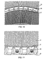
- Figures 10 and 11 are detail views, on a larger scale of the figure 9.
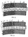
- Figure 12 illustrates a variant according to which, instead of having parallelepiped cavities C cylindrical cavities or blind holes are available Some may be connected to conduits 50.
- the annular ring of the rotor 41 (42,43) which cooperates with the ring 33 (34, 35) is arranged to be substantially at the middle of the cavities C or cylindrical holes D.
- Arrow F illustrates how dough from the area below crowns 33, 41 is forced into a cavity C or D, this cavity and the crown 41 forming a baffle that significantly slows the speed of the dough.
- FIG. 14 illustrates another variant embodiment in which the same elements bear the same references.
- the screen 30 is fixed and placed outside the rotor 40 which 45.
- the ring 41 of the rotor 40 is in front of the ring 33 of the sieve 30 so that the cavities C of said ring 33 form with the annular ring 41 a series of baffles.
- a pipe 50 which is a water pipe.
- the filter element constituted by the screen 30 and the rotor 40 is thus divided in three areas X, Y and Z from the bottom.
- the pulp to be purified arrives at Q at the base of the device.
- Zone X has an output 60 for the so-called "accepted” products, that is to say who passed through the sieve 30; zone Y has an output 61 for Accepted products and Zone Z an exit 62 for accepted products.
- thickening causes a decrease in the efficiency of the declogging which must be compensated for example by a higher speed and therefore a higher energy consumption.
- the introduction of water into ducts 50 which open into certain cavities C or D of the crown 34 and the ring 33 makes it possible to counter this thickening and thus makes it possible to reduce the rotor speed and thus save energy.
- the apparatus comprises a cover 63, an output R for the rejects.
- the speed of the rotor 40 can be adjusted according to the pressure differential between the entry Q in the apparatus and at least one of the pressures prevailing in the outlet ducts of accepted products 60, 61, 62.
- the sieve can be made in many ways either by stacking rings to U-section of Figures 1 to 6, either by stacking grids obtained by juxtaposition of bars of Figures 12 and 13, or by stacking the sheets perforated cylindrical holes or slits of Figure 15.
- they may be constituted by plates 70, in the mass of which were hollowed with circular milling grooves 71, the slots are then machined with circular saws.
- the rotor 40 being divided into as many portions as the sieve 30 can at each portion of the rotor have different blades 45 as to their number, their form, and their inclination.
- edges of the cavities C or D are exactly at the same level as that of the inner wall of the sieve 30.
Abstract
Description
La présente invention se rapporte aux problèmes de la filtration de la pâte à papier et plus particulièrement de la pâte à papier provenant de la mise en pulpe de vieux papiers.The present invention relates to the problems of pulp filtration at paper and more particularly pulp from pulping old papers.
Il est connu, dans la technologie de la pâte à papier d'employer divers appareils de filtration soit pour éliminer des corps étrangers soit pour classer les fibres de pâte à papier selon leur longueur soit encore pour augmenter la concentration de la pâte à papier par élimination partielle d'eau.It is known, in the technology of the pulp to employ various filtration apparatus either to remove foreign matter or to classify pulp fibers according to their length is again to increase the concentration of the pulp by partial removal of water.
Parmi les appareils de filtration connus figurent des filtres comprenant un rotor et un stator, l'un des deux, ci-après appelé tamis remplissant la fonction de filtrage comportant des perçages tels que des fentes ou des trous, l'autre ci-après appelé décolmateur, remplissant la fonction de décolmatage comportant des moyens destinés à générer des pulsations de pression pour empêcher le bouchage des perçages. Le tamis peut donc être fixe ou tournant et, à l'inverse, le décolmateur est tournant avec un tamis fixe et, fixe avec un tamis tournant. De plus le liquide peut soit s'écouler à travers le tamis de l'extérieur vers l'intérieur (vers l'axe), fonctionnement dit centripète, soit de l'intérieur vers l'extérieur, fonctionnement dit centrifuge.Among the known filtration apparatus are filters comprising a rotor and a stator, one of two, hereinafter referred to as sieves fulfilling the function of filtering with holes such as slots or holes, the other below called decolator, fulfilling the declogging function with means for generating pressure pulsations to prevent clogging holes. The sieve can therefore be fixed or rotating and, conversely, the decolator is rotating with a fixed sieve and fixed with a rotating sieve. Of the more the liquid can either flow through the sieve from the outside to the inside (towards the axis), so-called centripetal operation, either from the inside to the outside, said centrifugal operation.
Dans ce type d'appareil, la pâte arrive à une extrémité du tamis cylindrique, s'écoule dans l'espace compris entre le tamis cylindrique et le décolmateur, et ressort à l'autre extrémité.In this type of apparatus, the dough arrives at one end of the cylindrical sieve, flows in the space between the cylindrical sieve and the decolator, and spring at the other end.
Au fur et à mesure que la pâte progresse dans le filtre, elle devient de plus en plus épaisse.As the dough progresses in the filter, it becomes more in thicker.
Cet épaississement progressif de la pâte produit plusieurs effets : un effet de floculation de la pâte et un effet de colmatage du tamis.This gradual thickening of the dough produces several effects: an effect of flocculation of the dough and a clogging effect of the sieve.
Même si la pâte admise a été au préalable bien défloculée, il risque d'y avoir apparition de flocs au fur et à mesure de sa progression ; plus la floculation est importante, plus le colmatage est important.Even if the admixed pulp has been previously deflocculated, there is a risk of appearance of flocks as it progresses; the more flocculation is important, the more clogging is important.
Si le décolmateur tourne, il a tendance à entraíner la pâte avec lui en rotation. Si le décolmateur est fixe, c'est le filtre qui a tendance à entraíner la pâte en rotation. Dans les deux cas, comme l'effet du décolmatage par les pulsations de pression provoquées par le décolmateur est directement lié à l'écart de vitesse entre le décolmateur et la pâte, plus la pâte progresse vers l'extrémité du tamis, moins le décolmatage est efficace et ceci alors que le tamis a plus tendance à se colmater.If the decolator turns, it tends to drive the dough with him in rotation. If the decolator is fixed, it is the filter that tends to cause the dough in rotation. In both cases, as the effect of declogging by the pulsations of pressure caused by the decolator is directly related to the speed difference between the decolator and the dough, the dough progresses towards the end of the sieve, less unclogging is effective and this while the sieve is more likely to seal.
En outre, avec un tamis à fentes fines les fibres longues ont plus de mal à passer que les fibres courtes et donc la proportion de fibres longues par rapport aux fibres courtes augmente au fur et à mesure de la progression de la pâte, ce qui accélère à la fois le processus de floculation et celui de colmatage.In addition, with a sieve with fine slits the long fibers have more trouble in pass that short fibers and therefore the proportion of long fibers compared short fibers increases as the dough progresses, which accelerates both the flocculation process and the clogging process.
Il résulte de cette accumulation de phénomènes une réduction progressive de la production par unité de surface du tamis au fur et à mesure de la progression de la pâte dans le filtre.It results from this accumulation of phenomena a progressive reduction production per unit area of the sieve as and when progress of the dough in the filter.
De nombreux brevets ont eu pour objet de contrer cette réduction progressive de la productivité du filtre en intervenant, au cours du trajet le long du tamis, afin de créer des zones de forte défloculation, et/ou de fort ralentissement de la pâte.Many patents have aimed to counter this reduction of filter productivity by intervening during the journey along the sieves, in order to create areas of high deflocculation, and / or slow down dough.
En particulier, dès 1968 dans son brevet français 1.539.846 la demanderesse a proposé de disposer des obstacles ayant pour but de briser la composante parallèle à la surface du tamis de la vitesse du liquide.In particular, from 1968 in his French patent 1,539,846 the plaintiff proposed to have obstacles to break the component parallel to the surface of the sieve of the velocity of the liquid.
Dans le brevet US 4.383.918 on a proposé de disposer entre le tamis et le rotor des obstacles provoquant des turbulences.In US Pat. No. 4,383,918 it has been proposed to arrange between the sieve and the rotor obstructions causing turbulence.
Dans le brevet FR 2.613.390, également au nom de la demanderesse on a proposé de séparer le tamis en plusieurs portions et d'introduire de l'eau de dilution entre les portions du tamis.In patent FR 2,613,390, also in the name of the applicant, proposed to separate the sieve into several portions and to introduce water from dilution between the portions of the sieve.
Dans le brevet anglais GB 2.222.967 on a proposé d'installer deux tamis séparés par des ailettes fixes placées entre la surface des tamis et le rotor.In British Patent GB 2,222,967 it has been proposed to install two screens separated by fixed vanes placed between the sieve surface and the rotor.
Tous ces dispositifs ont peu à peu amélioré le fonctionnement des appareils de filtration constitués d'un tamis et d'un décolmateur mais de façon encore insuffisante.All these devices have gradually improved the operation of the devices filtration systems consisting of a sieve and a decolator but still insufficient.
Selon la présente invention :
- la zone d'augmentation de l'écart de vitesse peut comprendre une ou plusieurs chicanes ;
- les zones de défloculation et d'augmentation de l'écart de vitesse peuvent être combinées.
- the speed difference increasing zone may comprise one or more baffles;
- areas of defloculation and speed gap increase can be combined.
La présente invention concerne un appareil de filtration du type comportant un tamis de forme cylindrique et un décolmateur muni de pales qui produisent des fluctuations de pression pour lutter contre le colmatage dudit tamis, ce dernier étant en au moins deux parties de diamètre sensiblement équivalent séparées l'une de l'autre par des moyens ayant pour but de briser la composante de la vitesse du liquide, qui est parallèle à la surface du tamis et de créer des turbulences, caractérisé par le fait que lesdits moyens sont des chicanes constituées d'une part par des cavités ménagées dans une couronne annulaire du tamis disposée entre lesdites parties du tamis et d'autre part par un déflecteur annulaire porté par le décolmateur en face de chaque couronne du tamis portant les cavités, de telle sorte que la majorité du flux liquide soit obligée de traverser les cavités.The present invention relates to a filtration apparatus of the type comprising a cylindrical sieve and a decolator equipped with blades that produce pressure fluctuations to fight against the clogging of said sieve, the latter being in at least two parts of substantially equal diameter from each other by means intended to break the component of the velocity of the liquid, which is parallel to the surface of the sieve and to create turbulence, characterized in that said means are baffles formed on the one hand by cavities formed in an annular ring of the sieve disposed between said sieve parts and secondly by a deflector annular carried by the decolator in front of each crown of the sieve bearing the cavities, so that the majority of the liquid flow is forced to cross the cavities.
La présente invention peut comporter en outre tout ou partie des
dispositions suivantes, prises ensemble ou séparément :
La présente invention vise aussi un procédé d'utilisation de cet appareil pour le traitement de la pâte à papier selon lequel chaque partie de l'appareil de filtration comporte une sortie de produits acceptés et chaque couronne annulaire du tamis comporte éventuellement une arrivée de dilution l'appareil de filtration comportant en outre une entrée et une sortie des rejets, et selon lequel en jouant sur les réglages des sorties de produits acceptés, de la sortie des rejets et des arrivées de dilution par les canalisations, on réduit la vitesse de rotation du décolmateur de façon à ce qu'elle soit la plus basse possible afin d'économiser l'énergie, tout en maintenant un faible débit des rejets.The present invention also provides a method of using this apparatus for the treatment of paper pulp according to which each part of the apparatus of filtration includes an output of accepted products and each annular ring of the sieve optionally has a dilution inlet the filtration apparatus further comprising an input and an output of the rejects, and according to which by playing on the settings of the accepted product exits, the release of the rejects and the arrivals dilution of the pipes reduces the rotation speed of the decolator so that it is as low as possible in order to save energy, while maintaining a low discharge rate.
Le procédé selon l'invention peut comprendre les phases suivantes
consistant à :
La présente invention vise également la mise en oeuvre des moyens ci-dessus décrits pour la filtration de la pâte à papier.The present invention also aims at the implementation of the above means described for filtering pulp.
A titre d'exemples non limitatifs et pour faciliter la compréhension de
l'invention, on a représenté aux dessins annexés :
Dans toutes les figures 1 à 6, le tamis est constitué, comme cela a été décrit
dans le brevet EP 0 707 109 par un empilage de cercles 1 à section en U, pressés
les uns contre les autres au moyen de deux couronnes d'extrémités 2 et 3
assemblées l'une à l'autre par des tirants 4 qui permettent d'établir une
précontrainte. Les bases des U sont munies de perçages (que ce soient des fentes
ou des trous).In all of Figures 1 to 6, the sieve is constituted, as has been described
in patent EP 0 707 109 by a stack of circles 1 with U section, pressed
against each other by means of two
La pâte arrive dans le filtre par son extrémité située à gauche de la figure
(du côté de la couronne 2) et ressort par son extrémité opposée (du côté de la
couronne 3) en circulant dans l'espace 6 situé entre le décolmateur 5 et le tamis
comme indiqué par la flèche f1.The dough arrives in the filter by its end to the left of the figure
(on the side of the crown 2) and emerges by its opposite end (on the side of the
3) circulating in the
Il est à noter toutefois que l'invention n'est pas limitée à cette structure particulière de tamis mais est applicable à tout tamis cylindrique comme cela sera décrit ci-après.It should be noted, however, that the invention is not limited to this structure particular sieve but is applicable to any cylindrical sieve as it will described below.
Selon l'invention on crée une zone de ralentissement de la vitesse à laquelle la pâte est entraínée.According to the invention, a slowdown zone is created for the speed at which the dough is driven.
Dans ce but, comme cela est illustré aux figures 1 et 2, on dispose dans le tamis une série de chicanes qui ralentissent le mouvement tournant de la pâte.For this purpose, as illustrated in FIGS. 1 and 2, there is available in the sieve a series of baffles that slow down the rotating motion of the dough.
En se reportant à ces figures on voit que l'on remplace un ou plusieurs
cercles 1 par une pluralité de cloisons 20, parallèles à l'axe du filtre qui avec les
rebords des deux anneaux 1 qui l'encadrent constituent une pluralité de cavités
parallélépipédiques C disposées sur tout le pourtour du tamis. Referring to these figures we see that we replace one or more
circles 1 by a plurality of
En face de ces cloisons 20 est disposée une cloison annulaire 21
perpendiculaire à l'axe du filtre et portée par le rotor 5.In front of these
Ainsi, comme cela est représenté par la flèche f2, le flux de pâte est dévié
par la cloison annulaire 21 et vient heurter les cloisons 20 qui sont liées au tamis
et traverse les cavités C pour retourner dans l'espace 6.Thus, as represented by the arrow f2, the flow of dough is diverted
by the
Cela provoque un ralentissement de la vitesse de rotation de la pâte et, en même temps, une agitation de la pâte qui a un effet de défloculation et de fluidisation.This causes a slowing of the speed of rotation of the dough and, in same time, a stirring of the dough which has a deflocculation effect and fluidization.
On entend par fluidisation un état agité et sans floc de la pâte qui favorise l'écoulement dans les ouvertures, trous ou fentes du tamis.Fluidization is understood to mean a stirred and floc-free state of the dough which favors the flow in the openings, holes or slots of the sieve.
Il en résulte que le tamis est divisé en deux parties ; une première partie en amont de la couronne de cavités C et une deuxième partie en aval, ces deux parties étant séparées l'une de l'autre par la couronne de cavités C.As a result, the sieve is divided into two parts; a first part in upstream of the crown of cavities C and a second part downstream, these two parts being separated from each other by the crown of cavities C.
Il en résulte également que le rotor est divisé en deux parties par la cloison
circulaire 21.It also results that the rotor is divided into two parts by the
A la figure 1, la chicane 20/21 est disposée au milieu du tamis ; à la figure 3
elle est disposée à proximité de l'extrémité, c'est-à-dire là où les effets de
colmatage sont les plus importants du fait de l'épaississement de la pâte.In Figure 1, the
La figure 4 réunit les dispositions des figures 1 et 3.Figure 4 combines the provisions of Figures 1 and 3.
Selon l'exemple illustré à la figure 5 des turbulences sont en plus créées par
des ailettes 10 fixées sur le décolmateur et des ailettes 11 fixées sur le tamis.According to the example shown in Figure 5 turbulence is also created by
Ces ailettes 10 et 11 peuvent être radiales ou inclinées et peuvent avoir des
inclinaisons en sens inverse.These
De préférence, comme cela est représenté à la figure 5 les formes des
ailettes 10/11 sont telles qu'elles s'imbriquent les unes dans les autres.Preferably, as shown in FIG.
On obtient ainsi dans la zone où se trouvent lesdites ailettes une violente agitation qui réalise une bonne défloculation de la pâte.Thus, in the zone where the said fins are located, a violent stirring which achieves a good deflocculation of the dough.
La figure 6 représente un filtre centripète qui utilise les moyens de la figure 1. Les mêmes éléments portent les mêmes références.FIG. 6 represents a centripetal filter that uses the means of FIG. 1. The same elements bear the same references.
Sur cette figure, le tamis 1 se trouve à l'intérieur du décolmateur 5. La pâte
arrive par l'extrémité du tamis et circule dans l'espace 6 situé entre le tamis 1 et le
décolmateur 5. In this figure, the sieve 1 is inside the
Dans une zone du tamis 1, les cercles à section en U sont remplacés par des
cloisons 20, parallèles à l'axe du cylindre, et le décolmateur 5 comporte une
cloison annulaire 21.In a zone of the sieve 1, the U-section circles are replaced by
Comme dans le cas de la figure 1, la pâte est déviée par la cloison annulaire
21 et vient heurter les cloisons 20.As in the case of Figure 1, the paste is deflected by the
Les figures 7 à 17 représentent une variante de réalisation de l'appareil mettant en oeuvre le procédé selon la présente invention.Figures 7 to 17 show an alternative embodiment of the apparatus implementing the method according to the present invention.
La figure 7 représente un tamis cylindrique 30 qui est constitué de barrettes
31 disposées verticalement les unes à côté des autres avec un léger jeu (compris
entre 0.05 mm et 1 mm) et fixées sur des couronnes horizontales 32, 33, 34, 35,
36 et 37.FIG. 7 represents a
Ces couronnes 32 à 37 sont traversées par des tirants 38, parallèles à l'axe
du cylindre, ces tirants 38 étant fixés aux deux couronnes d'extrémités 32 et 37,
de sorte que l'ensemble est maintenu par le serrage des tirants 38.These
La figure 8 représente le rotor 40 qui est placé à l'intérieur du tamis de la
figure 7. Ce rotor est un cylindre qui comporte trois couronnes annulaires 41, 42,
et 43. Dans les zones comprises entre les couronnes annulaires sont disposées des
pales 45, appelées usuellement «foils» dans l'industrie de la pâte à papier.FIG. 8 shows the
Les foils 45 ont pour fonction de provoquer des pulsations de
pression/dépression qui tendent à empêcher le colmatage du tamis.The function of the
Les couronnes 41 à 43 sont disposées sur le rotor de façon à être en face
des couronnes 33, 34 et 35.The
Il sera expliqué ci-après comment les couronnes 33, 34 et 35 du tamis 30,
coopèrent avec les couronnes 41, 42 et 43 du rotor pour former des chicanes.It will be explained hereinafter how the
Comme on le voit sur la figure 8, les couronnes annulaires 41, 42 et 43
définissent quatre zones du rotor 40.As can be seen in FIG. 8, the annular rings 41, 42 and 43
define four zones of the
La forme, le nombre et l'inclinaison des pales ou foils 45 peuvent varier d'une zone à l'autre.The shape, number and inclination of the blades or foils 45 may vary from one area to another.
La figure 9 représente le tamis de la figure 7 vu de l'intérieur.Figure 9 shows the screen of Figure 7 seen from the inside.
On voit que les couronnes 33, 34 et 35 sont creuses de façon à définir des
cavités C.We see that the
Dans cet exemple, comme le tamis 30 est fait de barreaux 31 juxtaposés, les
cavités C ne sont pas faites comme dans le cas des figures 1 à 6 où le tamis était
constitué par des U. In this example, as the
Comme on le voit à la figure 9 les couronnes 33, 34, 35 sont constituées par
un anneau comportant une multitude de cavités parallélépipédiques ayant
pratiquement la même forme que les cavités C des figures 1 à 6.As seen in FIG. 9, the
Certaines cavités C des couronnes 33 et/ou 34 comportent en outre des
orifices qui sont reliés à des conduites 50 d'arrivée de dilution.Some cavities C crowns 33 and / or 34 further comprise
orifices which are connected to
Les figures 10 et 11 sont des vues de détail, à plus grande échelle de la figure 9.Figures 10 and 11 are detail views, on a larger scale of the figure 9.
La figure 12 illustre une variante selon laquelle, au lieu de disposer des
cavités parallélépipédiques C on dispose des cavités cylindriques ou trous borgnes
D, certains pouvant être reliés à des conduites 50.Figure 12 illustrates a variant according to which, instead of having
parallelepiped cavities C cylindrical cavities or blind holes are available
Some may be connected to
Comme cela est illustré à la figure 12 (trous borgnes D) et à la figure 13 (cavités parallélépipédiques C) la couronne annulaire du rotor 41 (42,43) qui coopère avec la couronne 33 (34, 35) est disposée de façon à être pratiquement au niveau du milieu des cavités C ou trous cylindriques D.As shown in Figure 12 (blind holes D) and Figure 13 (parallelepiped cavities C) the annular ring of the rotor 41 (42,43) which cooperates with the ring 33 (34, 35) is arranged to be substantially at the middle of the cavities C or cylindrical holes D.
La flèche F illustre comment de la pâte venant de la zone située en dessous
des couronnes 33, 41 est forcée à entrer dans une cavité C ou D, cette cavité et la
couronne 41 formant une chicane qui ralentit considérablement la vitesse de la
pâte.Arrow F illustrates how dough from the area below
crowns 33, 41 is forced into a cavity C or D, this cavity and the
On voit sur ces figures que les barrettes 31 sont maintenues par des
cerclages 31a.It can be seen in these figures that the
La figure 14 illustre une autre variante de réalisation dans laquelle les mêmes éléments portent les mêmes références.FIG. 14 illustrates another variant embodiment in which the same elements bear the same references.
Dans cet exemple, le tamis 30 est fixe et placé à l'extérieur du rotor 40 qui
porte des foils 45. La couronne 41 du rotor 40 est en face de la couronne 33 du
tamis 30 de façon à ce que les cavités C de ladite couronne 33 forment avec la
couronne annulaire 41 une série de chicanes.In this example, the
Sur cette figure, dans le fond de la cavité C arrive une conduite 50 qui est
une conduite d'eau.In this figure, in the bottom of the cavity C arrives a
Cela permet de combiner l'action de ralentissement provoquée par les chicanes C à une action de dilution de la pâte, qui a tendance à s'épaissir au fur et à mesure qu'elle traverse l'appareil de filtration.This makes it possible to combine the slowdown action caused by baffles C to a dilution action of the dough, which tends to thicken as and when as it passes through the filtration apparatus.
En se reportant à la figure 16, on voit que l'élément de filtration selon l'invention peut comporter, du haut vers le bas :
- une couronne d'extrémité supérieure 32 pour
le tamis 30, - une couronne intermédiaire 33 comportant une pluralité de cavités C, dont certaines sont reliées à des conduites 50 de dilution,
- une deuxième couronne intermédiaire 34, analogue à la couronne 33,
- une couronne d'extrémité inférieure 37, reliée à la couronne 32 par des tirants, non représentés,
- une couronne annulaire 41, portée par le rotor, et située en face des cavités C de la couronne 33 pour définir avec elle une pluralité de chicanes,
- une deuxième couronne annulaire 42, portée par le rotor, située en face des cavités C de la couronne 34.
- an
upper end ring 32 for thesieve 30, - an
intermediate ring 33 comprising a plurality of cavities C, some of which are connected todilution pipes 50, - a second
intermediate ring 34, similar to thering gear 33, - a
lower end ring 37, connected to thering 32 by tie rods, not shown, - an
annular ring 41, carried by the rotor, and located in front of the cavities C of thering 33 to define with it a plurality of baffles, - a second
annular ring 42, borne by the rotor, situated in front of the cavities C of thering 34.
L'élément de filtration constitué par le tamis 30 et le rotor 40 est ainsi divisé
en trois zones X, Y et Z en partant du bas.The filter element constituted by the
La pâte à épurer arrive en Q à la base du dispositif.The pulp to be purified arrives at Q at the base of the device.
La zone X comporte une sortie 60 pour les produits dits «acceptés» c'est-à-dire
qui ont traversé le tamis 30 ; la zone Y comporte une sortie 61 pour les
produits acceptés et la zone Z une sortie 62 pour les produits acceptés.Zone X has an
Il est bien évident que la pâte va avoir tendance à s'épaissir et à floculer au fur et à mesure qu'elle passe d'une zone à l'autre.It is obvious that the dough will tend to thicken and flocculate at as it moves from one area to another.
Comme on l'a dit, l'épaississement provoque une baisse de l'efficacité du
décolmatage qui doit être compensée par exemple par une vitesse plus élevée et
donc une consommation d'énergie plus importante. L'introduction d'eau dans les
conduits 50 qui débouchent dans certaines cavités C ou D de la couronne 34 et de
la couronne 33 permet de contrer cet épaississement et ainsi permet de réduire la
vitesse du rotor et donc d'économiser de l'énergie.As has been said, thickening causes a decrease in the efficiency of the
declogging which must be compensated for example by a higher speed and
therefore a higher energy consumption. The introduction of water into
A sa partie supérieure l'appareil comporte un couvercle 63, une sortie R pour
les rejets.At its upper part the apparatus comprises a
On peut ajuster la vitesse du rotor 40 en fonction du différentiel de pression
entre l'entrée Q dans l'appareil et l'une au moins des pressions régnant dans les
conduits de sortie des produits acceptés 60, 61, 62.The speed of the
On peut également ajuster la vitesse du rotor 40 en fonction d'un ou
plusieurs des débits dans les canalisations 60, 61 ou 62.It is also possible to adjust the speed of the
Dans l'un ou l'autre cas cela permet de réduire la vitesse de rotation du rotor
40 et donc de réaliser une économie d'énergie.In either case it reduces the rotation speed of the
Le tamis peut être réalisé de multiples façons soit par empilage d'anneaux à section en U des figures 1 à 6, soit par empilage de grilles obtenues par juxtaposition de barreaux des figures 12 et 13, soit par empilage des tôles cylindriques perforées à trous ou à fentes de la figure 15.The sieve can be made in many ways either by stacking rings to U-section of Figures 1 to 6, either by stacking grids obtained by juxtaposition of bars of Figures 12 and 13, or by stacking the sheets perforated cylindrical holes or slits of Figure 15.
Ainsi, par exemple, elles peuvent être constituées par des plaques 70, dans
la masse desquelles on a creusé avec des fraises circulaires des rainures 71, les
fentes étant ensuite usinées avec des scies circulaires.Thus, for example, they may be constituted by
Il est à noter qu'en disposant les pales 45 de décolmatage de façon inclinée
on obtient une sorte de pompage qui accélère la circulation dans l'appareil.It should be noted that by disposing the
Il est aussi à noter que le rotor 40 étant divisé en autant de portions que le
tamis 30 on peut à chaque portion du rotor disposer des pales 45 différentes
quant à leur nombre, leur forme et leur inclinaison.It should also be noted that the
De la même façon les différentes portions du tamis peuvent être de constitutions différentes.In the same way the different portions of the sieve can be different constitutions.
Dans tous les exemples représentés, les bords des cavités C ou D sont
exactement au même niveau que celui de la paroi interne du tamis 30.In all the examples shown, the edges of the cavities C or D are
exactly at the same level as that of the inner wall of the
Il est possible de les disposer de façon qu'ils fassent légèrement saillie à
l'intérieur du tamis 30, mais à condition que cela n'empêche pas l'introduction du
rotor 40 dans le tamis 30, c'est-à-dire que les couronnes annulaires telles que 41,
42 etc... puissent passer.It is possible to arrange them so that they project slightly to
inside the
Claims (17)
- Filtration apparatus of the type comprising a sieve (30) of a cylindrical form and a scourer (40), provided with blades (45) which produce pressure fluctuations in order to combat clogging-up of said sieve, the latter being in at least two parts of a substantially equivalent diameter, separated from each other by means, the purpose of which is to break up the component of the speed of the liquid, which is parallel to the surface of the screen, and to create turbulences, characterised by the fact that said means are baffles formed on the one hand by cavities (C, D) provided in an annular ring (33, 34, 35) of the sieve, said ring being disposed between said parts of the sieve and, on the other hand, by an annular deflector (21, 41, 42, 43) which is carried by the scourer opposite each ring of the sieve carrying the cavities, in such a manner that the majority of the liquid flow is forced to pass through the cavities.
- Filtration apparatus according to claim 1, in which the sieve (30) comprises a stack of rings.
- Filtration apparatus according to claim 1, in which the sieve (30) comprises a stack of screens, each screen being obtained by the juxtaposition of wires (31), either substantially parallel to the axis of rotation of the rotor (40) or perpendicular to this axis, or inclined.
- Filtration apparatus according to claim 1, in which the sieve (30) comprises a stack of cylindrical sheets with holes or slits.
- Filtration apparatus according to claim 1, in which the various parts of the sieve (30) are formed in a different manner from each other.
- Filtration apparatus according to any of the claims 1 to 5, in which the cavities are parallelepipeds (C).
- Filtration apparatus according to any of the claims 1 to 5, in which the cavities are cylindrical hollow volumes (D).
- Filtration apparatus according to any of the claims 6 or 7, in which certain cavities are connected to a dilution conduit (50).
- Filtration apparatus according to one of the claims 1 to 8, in which the number, the type, the thickness and the inclination of the blades (45) carried by the scourer (40) can vary between the annular deflectors (41, 42....).
- Filtration apparatus according to any of the preceding claims, characterised by the fact that it comprises furthermore a zone of violent agitation disposed at the inlet of the sieve.
- Filtration apparatus according to claim 10, characterised by the fact that the turbulences in the zone of violent agitation disposed at the inlet of the sieve are created by vanes (10) which are fixed on the scourer and vanes (11) which are fixed on the sieve.
- Method of using a filtration apparatus according to one of the preceding claims for the treatment of paper pulp.
- Method of using a filtration apparatus according to claim 12, according to which each part (X, Y, Z) of the filtration apparatus comprises an outlet for accepted products, (60, 61, 62) and each annular ring (33, 34) of the sieve (30) possibly comprises a dilution intake, the filtration apparatus furthermore comprising an inlet (Q) and an outlet (R) for rejects, and according to which, by acting upon the controls of the outlets for accepted products, of the outlet for rejects and of the intakes for dilution through the channels (50), the speed of rotation of the scourer (40) is reduced in such a manner that it is either the lowest possible in order to economise on power, whilst maintaining a low yield of rejects.
- Method of using a filtration apparatus according to claim 13, according to which the speed of the scourer (40) is adjusted as a function of the pressure differential between the inlet (Q) in the apparatus and one at least of the pressures prevailing in the outlet conduits (60, 61, 62) for the accepted products.
- Method of using a filtration apparatus according to claim 13, according to which the speed of the scourer (40) is adjusted as a function of one at least of the yields in the outlet conduits (60, 61, 62) for accepted products.
- Method of using a filtration apparatus according to claim 13, according to which the ratio of rejects from one or more parts of the sieve is adjusted by adjusting the yield of the outlet for rejects from the apparatus, taking into account the yields of the outlet for the accepted products and the yields of the intakes for dilution.
- Method of using a filtration apparatus according to at least two of the claims 14, 15 and 16.
Applications Claiming Priority (3)
| Application Number | Priority Date | Filing Date | Title |
|---|---|---|---|
| FR9902425 | 1999-02-26 | ||
| FR9902425A FR2790270B1 (en) | 1999-02-26 | 1999-02-26 | PROCESSES AND MEANS FOR FILTERING PULP |
| PCT/FR2000/000468 WO2000050690A1 (en) | 1999-02-26 | 2000-02-25 | Method and means for paper pulp filtering |
Publications (2)
| Publication Number | Publication Date |
|---|---|
| EP1155185A1 EP1155185A1 (en) | 2001-11-21 |
| EP1155185B1 true EP1155185B1 (en) | 2004-04-14 |
Family
ID=9542587
Family Applications (1)
| Application Number | Title | Priority Date | Filing Date |
|---|---|---|---|
| EP00907721A Expired - Lifetime EP1155185B1 (en) | 1999-02-26 | 2000-02-25 | Method and means for paper pulp filtering |
Country Status (12)
| Country | Link |
|---|---|
| US (1) | US6679384B1 (en) |
| EP (1) | EP1155185B1 (en) |
| JP (1) | JP4530545B2 (en) |
| AT (1) | ATE264425T1 (en) |
| AU (1) | AU2921400A (en) |
| BR (1) | BR0007868B1 (en) |
| CA (1) | CA2362500C (en) |
| DE (1) | DE60009869T2 (en) |
| ES (1) | ES2218131T3 (en) |
| FR (1) | FR2790270B1 (en) |
| NO (1) | NO317608B1 (en) |
| WO (1) | WO2000050690A1 (en) |
Cited By (1)
| Publication number | Priority date | Publication date | Assignee | Title |
|---|---|---|---|---|
| US7491296B2 (en) | 2002-06-07 | 2009-02-17 | Metso Paper, Inc. | Multi-stage screening apparatus, screen basket and method for screening pulp suspensions |
Families Citing this family (12)
| Publication number | Priority date | Publication date | Assignee | Title |
|---|---|---|---|---|
| JP4015527B2 (en) | 2002-10-16 | 2007-11-28 | 相川鉄工株式会社 | Screen device |
| AT413390B (en) * | 2003-03-27 | 2006-02-15 | Andritz Ag Maschf | SORTER FOR CLEANING A FIBER SUSPENSION |
| AT413391B (en) * | 2003-03-27 | 2006-02-15 | Andritz Ag Maschf | SORTER FOR CLEANING A FIBER SUSPENSION |
| SE526033C3 (en) | 2003-11-06 | 2009-12-08 | Metso Paper Inc | Screening device and strainer for screening of pulp suspensions |
| JP2005171449A (en) * | 2003-12-15 | 2005-06-30 | Aikawa Iron Works Co Ltd | Screen device for papermaking |
| US7393446B2 (en) * | 2004-03-05 | 2008-07-01 | Frank E. Towsley | Cellular metal structure |
| DE102004031622B4 (en) * | 2004-06-30 | 2006-06-14 | Voith Paper Patent Gmbh | Pressure sorter for sifting a pulp suspension |
| JP2006089884A (en) * | 2004-09-27 | 2006-04-06 | Aikawa Iron Works Co Ltd | Screening apparatus |
| JP4909693B2 (en) * | 2006-07-24 | 2012-04-04 | 相川鉄工株式会社 | Screen device |
| CA2793158C (en) | 2010-03-16 | 2017-07-04 | Tampulping Oy | Pressure filter |
| DE102010032350A1 (en) * | 2010-07-27 | 2012-02-02 | Automatic Plastics Machinery Gmbh | Device for drying granules |
| CN113215848B (en) * | 2021-04-30 | 2023-05-26 | 安德里茨(中国)有限公司 | Pressure screen and dilution method for a pressure screen |
Family Cites Families (13)
| Publication number | Priority date | Publication date | Assignee | Title |
|---|---|---|---|---|
| DE558447C (en) * | 1932-09-09 | J M Voith Fa | Centrifugal separator for wood pulp, pulp and Like. With horizontal wing shaft | |
| US1537691A (en) * | 1923-08-16 | 1925-05-12 | American Voith Contact Co | Centrifugal screen |
| DE558477C (en) | 1931-09-18 | 1932-09-07 | Frey & Co W | Bright annealing furnace for wires u. like |
| JPS61153114A (en) * | 1984-12-25 | 1986-07-11 | Mitsubishi Heavy Ind Ltd | Screening apparatus |
| FR2613390B1 (en) * | 1987-04-06 | 1995-01-20 | Lamort Sa E M | IMPROVEMENT IN SIEVES USED FOR PULP TREATMENT |
| FI77279C (en) * | 1987-04-30 | 1989-02-10 | Ahlstroem Oy | FOERFARANDE OCH ANORDNING FOER BEHANDLING AV FIBERSUSPENSION. |
| DE3831845A1 (en) * | 1988-09-19 | 1990-04-12 | Voith Gmbh J M | SORTING DEVICE FOR FIBER SUSPENSIONS |
| SU1669585A1 (en) * | 1989-04-26 | 1991-08-15 | Воронежский сельскохозяйственный институт им.К.Д.Глинки | Centrifugal separator |
| FI84191C (en) * | 1989-05-17 | 1992-11-25 | Ahlstroem Oy | Method and apparatus for treating fiber suspension |
| US5096127A (en) * | 1990-08-22 | 1992-03-17 | Ingersoll-Rand Company | Apparatus for pressurized screening of a fibrous material liquid suspension |
| FR2666598B1 (en) * | 1990-09-10 | 1994-05-27 | Escher Wyss Gmbh | PROCESS FOR SEPARATING, ESPECIALLY SORTING OR SPLITTING A SUSPENSION OF PAPER PULP. |
| SE507481C2 (en) * | 1996-05-02 | 1998-06-15 | Alfa Laval Ab | Device for separating impurities from fiber pulp suspensions |
| US6155427A (en) * | 1996-11-14 | 2000-12-05 | Thermo Black Clawson Inc. | Zoned pressure screen |
-
1999
- 1999-02-26 FR FR9902425A patent/FR2790270B1/en not_active Expired - Lifetime
-
2000
- 2000-02-25 US US09/890,787 patent/US6679384B1/en not_active Expired - Lifetime
- 2000-02-25 DE DE60009869T patent/DE60009869T2/en not_active Expired - Lifetime
- 2000-02-25 AU AU29214/00A patent/AU2921400A/en not_active Abandoned
- 2000-02-25 CA CA002362500A patent/CA2362500C/en not_active Expired - Fee Related
- 2000-02-25 EP EP00907721A patent/EP1155185B1/en not_active Expired - Lifetime
- 2000-02-25 AT AT00907721T patent/ATE264425T1/en active
- 2000-02-25 WO PCT/FR2000/000468 patent/WO2000050690A1/en active IP Right Grant
- 2000-02-25 ES ES00907721T patent/ES2218131T3/en not_active Expired - Lifetime
- 2000-02-25 JP JP2000601244A patent/JP4530545B2/en not_active Expired - Fee Related
- 2000-02-25 BR BRPI0007868-9A patent/BR0007868B1/en not_active IP Right Cessation
-
2001
- 2001-08-24 NO NO20014132A patent/NO317608B1/en not_active IP Right Cessation
Cited By (1)
| Publication number | Priority date | Publication date | Assignee | Title |
|---|---|---|---|---|
| US7491296B2 (en) | 2002-06-07 | 2009-02-17 | Metso Paper, Inc. | Multi-stage screening apparatus, screen basket and method for screening pulp suspensions |
Also Published As
| Publication number | Publication date |
|---|---|
| WO2000050690A1 (en) | 2000-08-31 |
| US6679384B1 (en) | 2004-01-20 |
| CA2362500A1 (en) | 2000-08-31 |
| BR0007868B1 (en) | 2010-04-06 |
| ATE264425T1 (en) | 2004-04-15 |
| JP2002537964A (en) | 2002-11-12 |
| NO20014132D0 (en) | 2001-08-24 |
| ES2218131T3 (en) | 2004-11-16 |
| DE60009869D1 (en) | 2004-05-19 |
| NO317608B1 (en) | 2004-11-22 |
| BR0007868A (en) | 2001-10-16 |
| DE60009869T2 (en) | 2005-04-21 |
| AU2921400A (en) | 2000-09-14 |
| EP1155185A1 (en) | 2001-11-21 |
| CA2362500C (en) | 2007-08-21 |
| NO20014132L (en) | 2001-10-12 |
| FR2790270B1 (en) | 2001-11-16 |
| FR2790270A1 (en) | 2000-09-01 |
| JP4530545B2 (en) | 2010-08-25 |
Similar Documents
| Publication | Publication Date | Title |
|---|---|---|
| EP1155185B1 (en) | Method and means for paper pulp filtering | |
| CA2671216C (en) | Apparatus for the separation of solid particles and hydraulic system comprising same | |
| EP1907091B1 (en) | Gravitational separation device for water treatment | |
| CH637029A5 (en) | ROTARY PULP FILTERING DEVICE. | |
| FR2645184A1 (en) | APPARATUS FOR FLUIDIZING, DEGASSING AND PUMPING A SUSPENSION OF A FIBROUS CELLULOSIC MATERIAL | |
| FR2578177A1 (en) | SCREENING DEVICE. | |
| FR2538715A1 (en) | AIR CLEANING DEVICE, IN PARTICULAR FOR INTERNAL COMBUSTION ENGINES | |
| EP0303655B1 (en) | Centrifugal action turbine | |
| EP0198737B1 (en) | Apparatus for the decontamination of paper pulp | |
| FR2617516A1 (en) | APPARATUS FOR DISTRIBUTING A FIBROUS CELLULOSIC PASTE | |
| EP0104966B1 (en) | Centrifuge with energy recuperation | |
| FR2478694A1 (en) | DISC SORTER FOR PURIFYING SUSPENSIONS OF FIBROUS MATERIALS | |
| FR2643396A1 (en) | APPARATUS FOR FILTERING A SUSPENSION OF FIBROUS CELLULOSIC MATERIAL | |
| EP0286535B1 (en) | Screens for paperstock cleaners | |
| FR2632332A1 (en) | SEPARATION APPARATUS FOR FIBROUS CELLULOSIC PASTE SUSPENSION | |
| EP0629738A1 (en) | Rotor for hydrodynamic pressure cleaning of paper pulp and apparatus using the rotor | |
| JP3595544B2 (en) | Stock separation equipment | |
| EP2181748B1 (en) | Hydrodynamic separator for cleaning a fluid stream | |
| FR2464329A1 (en) | FILTRATION DEVICE FOR THE THICKENING OF FIBROUS SUSPENSIONS | |
| EP0045705B1 (en) | Method and apparatus for separating suspensions of solid particles in a liquid, particularly for treating fibrous suspensions in the paper-making industry | |
| EP0249668B1 (en) | Apparatus for the centrifugal separation of a mixture of phases | |
| FR2682893A1 (en) | Process and machine for recovering metals in the free state which are contained in wet or dry alluvial deposits or in crushed rock | |
| CH651765A5 (en) | CENTRIFUGAL SEPARATION APPARATUS APPLICABLE IN PARTICULAR FOR THE PURIFICATION OF GASEOUS MIXTURES. | |
| BE436107A (en) | ||
| BE547968A (en) |
Legal Events
| Date | Code | Title | Description |
|---|---|---|---|
| PUAI | Public reference made under article 153(3) epc to a published international application that has entered the european phase |
Free format text: ORIGINAL CODE: 0009012 |
|
| 17P | Request for examination filed |
Effective date: 20010712 |
|
| AK | Designated contracting states |
Kind code of ref document: A1 Designated state(s): AT BE CH CY DE DK ES FI FR GB GR IE IT LI LU MC NL PT SE |
|
| GRAP | Despatch of communication of intention to grant a patent |
Free format text: ORIGINAL CODE: EPIDOSNIGR1 |
|
| RAP1 | Party data changed (applicant data changed or rights of an application transferred) |
Owner name: KADANT LAMORT |
|
| GRAS | Grant fee paid |
Free format text: ORIGINAL CODE: EPIDOSNIGR3 |
|
| GRAA | (expected) grant |
Free format text: ORIGINAL CODE: 0009210 |
|
| AK | Designated contracting states |
Kind code of ref document: B1 Designated state(s): AT BE CH CY DE DK ES FI FR GB GR IE IT LI LU MC NL PT SE |
|
| PG25 | Lapsed in a contracting state [announced via postgrant information from national office to epo] |
Ref country code: IE Free format text: LAPSE BECAUSE OF FAILURE TO SUBMIT A TRANSLATION OF THE DESCRIPTION OR TO PAY THE FEE WITHIN THE PRESCRIBED TIME-LIMIT Effective date: 20040414 Ref country code: NL Free format text: LAPSE BECAUSE OF FAILURE TO SUBMIT A TRANSLATION OF THE DESCRIPTION OR TO PAY THE FEE WITHIN THE PRESCRIBED TIME-LIMIT Effective date: 20040414 |
|
| REG | Reference to a national code |
Ref country code: GB Ref legal event code: FG4D Free format text: NOT ENGLISH |
|
| REG | Reference to a national code |
Ref country code: CH Ref legal event code: EP |
|
| GBT | Gb: translation of ep patent filed (gb section 77(6)(a)/1977) |
Effective date: 20040414 |
|
| REF | Corresponds to: |
Ref document number: 60009869 Country of ref document: DE Date of ref document: 20040519 Kind code of ref document: P |
|
| REG | Reference to a national code |
Ref country code: IE Ref legal event code: FG4D Free format text: FRENCH |
|
| PG25 | Lapsed in a contracting state [announced via postgrant information from national office to epo] |
Ref country code: GR Free format text: LAPSE BECAUSE OF FAILURE TO SUBMIT A TRANSLATION OF THE DESCRIPTION OR TO PAY THE FEE WITHIN THE PRESCRIBED TIME-LIMIT Effective date: 20040714 Ref country code: DK Free format text: LAPSE BECAUSE OF FAILURE TO SUBMIT A TRANSLATION OF THE DESCRIPTION OR TO PAY THE FEE WITHIN THE PRESCRIBED TIME-LIMIT Effective date: 20040714 |
|
| REG | Reference to a national code |
Ref country code: SE Ref legal event code: TRGR |
|
| NLV1 | Nl: lapsed or annulled due to failure to fulfill the requirements of art. 29p and 29m of the patents act | ||
| REG | Reference to a national code |
Ref country code: ES Ref legal event code: FG2A Ref document number: 2218131 Country of ref document: ES Kind code of ref document: T3 |
|
| REG | Reference to a national code |
Ref country code: IE Ref legal event code: FD4D |
|
| PLBE | No opposition filed within time limit |
Free format text: ORIGINAL CODE: 0009261 |
|
| STAA | Information on the status of an ep patent application or granted ep patent |
Free format text: STATUS: NO OPPOSITION FILED WITHIN TIME LIMIT |
|
| PG25 | Lapsed in a contracting state [announced via postgrant information from national office to epo] |
Ref country code: CY Free format text: LAPSE BECAUSE OF FAILURE TO SUBMIT A TRANSLATION OF THE DESCRIPTION OR TO PAY THE FEE WITHIN THE PRESCRIBED TIME-LIMIT Effective date: 20050225 Ref country code: LU Free format text: LAPSE BECAUSE OF NON-PAYMENT OF DUE FEES Effective date: 20050225 |
|
| PG25 | Lapsed in a contracting state [announced via postgrant information from national office to epo] |
Ref country code: BE Free format text: LAPSE BECAUSE OF NON-PAYMENT OF DUE FEES Effective date: 20050228 Ref country code: LI Free format text: LAPSE BECAUSE OF NON-PAYMENT OF DUE FEES Effective date: 20050228 Ref country code: CH Free format text: LAPSE BECAUSE OF NON-PAYMENT OF DUE FEES Effective date: 20050228 Ref country code: MC Free format text: LAPSE BECAUSE OF NON-PAYMENT OF DUE FEES Effective date: 20050228 |
|
| 26N | No opposition filed |
Effective date: 20050117 |
|
| BERE | Be: lapsed |
Owner name: *KADANT LAMORT Effective date: 20050228 |
|
| REG | Reference to a national code |
Ref country code: CH Ref legal event code: PL |
|
| BERE | Be: lapsed |
Owner name: *KADANT LAMORT Effective date: 20050228 |
|
| PG25 | Lapsed in a contracting state [announced via postgrant information from national office to epo] |
Ref country code: PT Free format text: LAPSE BECAUSE OF NON-PAYMENT OF DUE FEES Effective date: 20040914 |
|
| PGFP | Annual fee paid to national office [announced via postgrant information from national office to epo] |
Ref country code: GB Payment date: 20130218 Year of fee payment: 14 Ref country code: ES Payment date: 20130227 Year of fee payment: 14 |
|
| GBPC | Gb: european patent ceased through non-payment of renewal fee |
Effective date: 20140225 |
|
| PG25 | Lapsed in a contracting state [announced via postgrant information from national office to epo] |
Ref country code: GB Free format text: LAPSE BECAUSE OF NON-PAYMENT OF DUE FEES Effective date: 20140225 |
|
| REG | Reference to a national code |
Ref country code: ES Ref legal event code: FD2A Effective date: 20150506 |
|
| PG25 | Lapsed in a contracting state [announced via postgrant information from national office to epo] |
Ref country code: ES Free format text: LAPSE BECAUSE OF NON-PAYMENT OF DUE FEES Effective date: 20140226 |
|
| REG | Reference to a national code |
Ref country code: FR Ref legal event code: PLFP Year of fee payment: 17 |
|
| REG | Reference to a national code |
Ref country code: FR Ref legal event code: PLFP Year of fee payment: 18 |
|
| REG | Reference to a national code |
Ref country code: FR Ref legal event code: PLFP Year of fee payment: 19 |
|
| PGFP | Annual fee paid to national office [announced via postgrant information from national office to epo] |
Ref country code: DE Payment date: 20180219 Year of fee payment: 19 Ref country code: FI Payment date: 20180219 Year of fee payment: 19 |
|
| PGFP | Annual fee paid to national office [announced via postgrant information from national office to epo] |
Ref country code: AT Payment date: 20180219 Year of fee payment: 19 Ref country code: IT Payment date: 20180227 Year of fee payment: 19 Ref country code: FR Payment date: 20180226 Year of fee payment: 19 Ref country code: SE Payment date: 20180227 Year of fee payment: 19 |
|
| REG | Reference to a national code |
Ref country code: DE Ref legal event code: R119 Ref document number: 60009869 Country of ref document: DE |
|
| REG | Reference to a national code |
Ref country code: SE Ref legal event code: EUG |
|
| REG | Reference to a national code |
Ref country code: AT Ref legal event code: MM01 Ref document number: 264425 Country of ref document: AT Kind code of ref document: T Effective date: 20190225 |
|
| PG25 | Lapsed in a contracting state [announced via postgrant information from national office to epo] |
Ref country code: FI Free format text: LAPSE BECAUSE OF NON-PAYMENT OF DUE FEES Effective date: 20190225 Ref country code: SE Free format text: LAPSE BECAUSE OF NON-PAYMENT OF DUE FEES Effective date: 20190226 |
|
| PG25 | Lapsed in a contracting state [announced via postgrant information from national office to epo] |
Ref country code: AT Free format text: LAPSE BECAUSE OF NON-PAYMENT OF DUE FEES Effective date: 20190225 |
|
| PG25 | Lapsed in a contracting state [announced via postgrant information from national office to epo] |
Ref country code: DE Free format text: LAPSE BECAUSE OF NON-PAYMENT OF DUE FEES Effective date: 20190903 |
|
| PG25 | Lapsed in a contracting state [announced via postgrant information from national office to epo] |
Ref country code: FR Free format text: LAPSE BECAUSE OF NON-PAYMENT OF DUE FEES Effective date: 20190228 Ref country code: IT Free format text: LAPSE BECAUSE OF NON-PAYMENT OF DUE FEES Effective date: 20190225 |