EP1154449A2 - Manufacturing method of solid electrolytic capacitor - Google Patents
Manufacturing method of solid electrolytic capacitor Download PDFInfo
- Publication number
- EP1154449A2 EP1154449A2 EP01108939A EP01108939A EP1154449A2 EP 1154449 A2 EP1154449 A2 EP 1154449A2 EP 01108939 A EP01108939 A EP 01108939A EP 01108939 A EP01108939 A EP 01108939A EP 1154449 A2 EP1154449 A2 EP 1154449A2
- Authority
- EP
- European Patent Office
- Prior art keywords
- oxidative polymerization
- electrolytic capacitor
- solid electrolytic
- electroconductive polymer
- solution
- Prior art date
- Legal status (The legal status is an assumption and is not a legal conclusion. Google has not performed a legal analysis and makes no representation as to the accuracy of the status listed.)
- Granted
Links
Images


Classifications
-
- H—ELECTRICITY
- H01—ELECTRIC ELEMENTS
- H01G—CAPACITORS; CAPACITORS, RECTIFIERS, DETECTORS, SWITCHING DEVICES, LIGHT-SENSITIVE OR TEMPERATURE-SENSITIVE DEVICES OF THE ELECTROLYTIC TYPE
- H01G9/00—Electrolytic capacitors, rectifiers, detectors, switching devices, light-sensitive or temperature-sensitive devices; Processes of their manufacture
- H01G9/0029—Processes of manufacture
- H01G9/0036—Formation of the solid electrolyte layer
Definitions
- the present invention relates to a manufacturing method of a solid electrolytic capacitor, and more particularly to a manufacturing method of a solid electrolytic capacitor using an electroconductive polymer as a solid electrolyte layer.
- a solid electrolytic capacitor has a solid electrolyte layer such as manganese dioxide or lead dioxide on a dielectric film which is formed by oxidizing the surface of a porous anode body.
- the porous anode body is made by sintering a molded body of valve metal powder, such as tantalum or aluminum.
- a capacitor with a solid electrolyte layer of an electroconductive polymer such as a five-membered heterocyclic compound (e.g., polypyrrole and polythiophene) and polyaniline, which has a higher conductivity compared with that for the conventional solid electrolyte layer.
- This electroconductive polymer as a solid electrolyte layer is formed by chemical or electrochemical oxidative polymerization on the dielectric film such as Ta 2 O 5 made by anodizing electrochemically on the surface of the porous anode body.
- FIGs. 1A and 1B are sectional views of a small pore of the porous body element of a solid electrolytic capacitor to explain the formation of the electroconductive polymer layer in its pore by chemical oxidative polymerization after the formation of the dielectric in a conventional manufacturing method of a solid electrolytic capacitor with the electroconductive polymer electrolyte.
- a porous body element 6 with a dielectric film 3 formed on the surface is soaked in an oxidant solution (not shown in FIG.1A) to make the inside and the outside of a pore 10 of the porous body element 6 adsorb the oxidant. Then, the porous body element is soaked in a monomer solution. When the porous body element is soaked in the monomer solution, chemical oxidative polymerization starts and an electroconductive polymer layer 11, an electrolyte material, is formed before the monomer permeates enough into the pore 10 of the porous body element 6.
- an electroconductive polymer layer is formed by a chemical oxidative polymerization as follows.
- a porous body of a electrochemical valve metal with a dielectric film formed on the surface is soaked in a solution (hereinafter referred to as a "reaction solution") which contains a monomer, an oxidizing agent, and a dopant.
- reaction solution a solution which contains a monomer, an oxidizing agent, and a dopant.
- a porous body of a electrochemical valve metal with a dielectric film formed on the surface is soaked in the reaction solution and pulled out of the reaction solution after some of the reaction solution is adsorbed on the surface of the dielectric film. Then, chemical oxidative polymerization takes place in air and an electroconductive polymer layer is formed on the surface of the dielectric film. While the electroconductive polymer layer is forming on the surface of the dielectric film, the temperature of the porous body itself or of the spaces inside the pores is kept higher than that of the solution. In this technique, by keeping the porous body or inside temperature higher than the solution temperature, the chemical oxidative polymerization reaction rate inside the porous body becomes faster than outside and the production of the electroconductive polymer layer inside a small pore of the porous body is enhanced.
- a porous body with an oxide film (a dielectric film) on the surface is formed.
- the porous body is soaked in a monomer solution and then in an oxidant solution to form an electroconductive polymer layer on the oxide film.
- the soaking time of the porous body in the oxidant solution after soaking in the monomer solution is kept less than the time for 30 % of the monomer in the porous body to flow out by diffusion. And also the reaction temperature is decreased. As a result, the monomer outflow from the pores is decreased and the yield of the electroconductive polymer layer inside the pores of the porous body is increased.
- the outside of the porous body (dielectric film) is covered with the first electroconductive polymer layer and then the second electroconductive polymer layer is formed inside the dielectric film.
- the first electroconductive polymer layer is formed in a solution with a higher concentration of the oxidizing agent than the second electroconductive polymer layer so that a high polymerization rate is achieved and the electroconductive polymer layer can be formed preferentially on the surface except small pores, the outer surface of the dielectric film.
- the first electroconductive polymer layer prevents the solution for forming the second electroconductive polymer layer inside small pores from permeating, and as a result, it restricts the formation of the electroconductive polymer layer inside small pores because the outer surface of the porous body is already covered with the first layer.
- an object of the present invention is to provide a manufacturing method of a solid electrolytic capacitor using an electroconductive polymer as an electrolyte material which improves the capacitance appearance factor and equivalent series resistance in high frequency region.
- the manufacturing method of a solid electrolytic capacitor is characterized by comprising the steps of: contacting a dielectric film of a porous body made of an oxide film of a electrochemical valve metal with an oxidant solution; and contacting the dielectric film with an electroconductive polymer forming monomer solution to form the electrolyte layer made of the electroconductive polymer on the surface of the dielectric film by an oxidative polymerization reaction, wherein an oxidative polymerization retarding agent which delays the oxidative polymerization reaction, is added to at least one of the solutions, an oxidant solution and a monomer solution.
- the oxidative polymerization retarding agent is an additive to prevent the chemically-oxidative polymerization from occurring immediately when the oxidant and the monomer contact each other and to delay starting of the chemical oxidative polymerization reaction.
- Pyrrole, pyrrole derivatives, thiophene, tiophene derivatives, or aniline is used as a monomer.
- Oxime compounds nitro compounds, nitroso compounds, nitroxide compounds, chinone compounds, or phenol compounds is used as an oxidative polymerization retarding agent.
- Iron(II) sulfonate, sulfuric acid, or hydrogen peroxide is used as an oxidizing agent.
- the starting time of the polymerization to form an electroconductive polymer layer is delayed by using an oxidative polymerization retarding agent. Because the polymerization started after the monomer and the oxidizing agent solution have permeated well into small pores, the electroconductive polymer layer is formed inside small pores and the capacitance appearance factor and the equivalent series resistance of a solid electrolytic capacitor with an electroconductive polymer as an electrolyte material are improved.
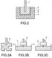
- FIGs. 2 and 3A to 3C The embodiments of the present invention are explained by referring to FIGs. 2 and 3A to 3C.
- the powder is press-formed and the wire and pressed powder are sintered to form a porous anode body 2.
- the anode body 2 is anodized in an aqueous solution of phosphoric acid to form a dielectric film 3 of tantalum oxide (Ta 2 O 5 ) on the surface of the anode body 2.
- a porous body element 6 is formed (FIGs. 2 and 3A).
- the porous body element 6 with the dielectric film 3 is soaked in an oxidant solution 7 for a predetermined time (FIG. 3B). After it is dried, as shown in FIG. 3C, it is soaked in a monomer solution containing an oxidative polymerization retarding agent (a mixed solution 8 of a monomer and an oxidative polymerization retarding agent) for a predetermined time. Then, the porous body element 6 is pulled out of the oxidant solution 7 and dried in air.
- an oxidative polymerization retarding agent a mixed solution 8 of a monomer and an oxidative polymerization retarding agent
- Iron(II) sulfonate e.g., iron(II) p-toluene sulfonate, iron(II) dodecylbenzene sulfonate, iron(II) benzene sulfonate, and iron(II) naphthalene sulfonate
- sulfuric acid e.g., sulfuric acid, or hydrogen peroxide
- hydrogen peroxide is used as a solution of the oxidant.
- Pyrrole, thiophene, their derivatives (e.g., 3,4-ethylenedioxythiophene and 3,4-dimethylpyrrole) or aniline is used as s solution of the monomer.
- Oxime compounds e.g., p-benzoquinone dioxime and diethyl ketone dioxime
- nitro compounds e.g., dinitrobenzene, nitrotoluene, 2,2-diphenyl-picryl-hydrazyl, and picric acid
- nitroso compounds e.g., n-nitroso phenylhydroxylamine ammonium salt, nitrosotoluene, and nitrosobenzene
- nitrooxide compounds e.g., 2,2,6,6-tetramethyl-1-1piperidyloxy, 4,4-dimethyl-3-oxazolinyloxy, 2,2,5,5-tetramethyl-1-pyrrolidinyloxy, 5,5-dimethyl-1-pyrroline-n-oxide, 2,5,5-trimethyl-1-pyrroline, n-tert-butyl- ⁇ -phenylnitrone, ⁇ -(4-pyridyl-1-oxide)
- the amount of the oxidative polymerization retarding agent added to the monomer solution is 0.1 to 20wt%, preferably 1 to 20wt%. The most preferred amount is 1 to 10wt%.
- the amount of the retarding agent added is less than 0.1wt%, the covering rate of the electrolyte layer 4 inside small pores of the dielectric film 3 decreases remarkably.
- the amount of the oxidative polymerization retarding agent is more than 20wt%, it is difficult to form the electrolyte layer 4 not only inside the small pores but also on the outer surface because the oxidative polymerization reaction of the monomer is suppressed remarkably.
- a cathode layer 5 is formed by forming a carbon paste and the silver paste successively on the surface of the electrolyte layer 4 and a capacitor element is completed.
- an external lead terminal is connected with each of the tantalum wire 1 in the capacitor element and a silver paste in the cathode layer 5, by sealing the capacitor element with a sealing resin such as an epoxy resin, the intended capacitor is manufactured.
- the oxidative polymerization retarding agent is mixed into a monomer solution in the above embodiment, it is possible to mix the retarding agent into the oxidant solution or to mix the retarding agent into both the monomer solution and the oxidant solution. In the case of adding the oxidative polymerization retarding agent into the oxidizing agent solution, the amount of the retarding agent is same as that into the monomer solution.
- the sum of the amount of the retarding agent added into the solutions is 0.1 to 20wt%.
- the sum total amount is preferably 1 to 20wt% and the most preferred amount is 1 to 10wt%.
- the sum total amount of the oxidative polymerization retarding agent is less than 0.1wt%, the covering rate of the electrolyte layer 4 into small pores decreases remarkably.
- the sum total amount of the retarding agent is more than 20wt%, it is difficult to form the electrolyte layer 4 not only inside the small pores but also on the outer surface because the oxidative polymerization reaction of the monomer is suppressed remarkably.
- Ta or another metal such as Al, Nb, or Ti is used as a metal powder having a valve-action.
- FIGs. 4A and 4B Next, the operations of the embodiment in the present invention are explained by referring to FIGs. 4A and 4B.
- the porous body element 6 is soaked in an oxidant solution to adhere the oxidant inside the element pore 10, and then soaked in a monomer solution.
- chemical oxidative polymerization starts and an electroconductive polymer layer 11 as an electrolyte material is formed before the monomer permeates into the element pore 10.
- the entrance of the element pore 10 is clogged with the electroconductive polymer layer 11 and the permeation of the oxidant or the monomer into the pores is disturbed in the repeating process to form the electroconductive polymer layer as follows.
- the oxidative polymerization retarding agent is mixed in at least one of the monomer solution and the oxidizing solution, when the monomer contacts with the oxidizing agent on the surface of the porous body element 6, the oxidative polymerization retarding agent contacts at the same time with the monomer and the oxidizing agent.
- the chemical oxidative polymerization reaction doesn't start at the moment the porous body element 6 is soaked in the monomer solution. Accordingly, the monomer permeates into small pores of the element before the polymerization starts, and thus an electroconductive polymer layer is formed inside the element pore without causing the blockage with the electroconductive polymer layer at the entrance of the pore.
- FIGs. 3A to 3C Preferred embodiments of the present invention are described below by referring to FIGs. 3A to 3C. However, the present invention is not limited to the embodiments.
- a rectangular parallelepiped tantalum powder sintered pellet having 1 mm long, 1mm wide, and 1mm high is anodized in 0.1wt% nitric acid solution at 33V to form a dielectric film on its surface and a porous body element 6 is obtained (FIG. 3A).
- porous body element 6 with a dielectric film is soaked in an oxidizing agent solution 7, a methyl alcohol solution with 40wt% iron(II) p-toluenesulfonate, for one minute (FIG. 3B). And, the element is pulled out of the oxidizing agent solution 7 and dried at room temperature.
- the element is soaked in a monomer/oxidative polymerization retarding agent mixture solution 8 obtained by adding 10wt% p-benzoquinone as a retarding agent to a pyrrole solution, for one minute (FIG. 3C). Then, the porous body element 6 is pulled out of the monomer/oxidative polymerization retarding agent mixture solution 8 and kept in air for 30 min. By repeating this step three times, an electroconductive polymer layer of polypyrrole is formed on the surface of the porous body element 6. Then the porous body element 6 with an electroconductive polymer layer is cleaned with butyl alcohol for 30 min. It is possible to use isopropyl alcohol instead of the butyl alcohol for the cleaning.
- a carbon paste and a silver paste are sequentially formed on the surface of the electrolyte layer 4, dried to form a cathode layer 5, and a capacitor element is completed.
- a sealing resin such as an epoxy resin
- a capacitor is completed in the same manner as in Example 1, except that the pyrrole for forming an electroconductive polymer layer in Example 1 is replaced by thiophene.
- the porous body element 6 is formed (FIG. 3A)
- the porous body element 6 is soaked in an oxidizing agent solution 7, a methyl alcohol solution with 40wt% iron(II) p-toluenesulfonate, for one minute (FIG. 3B). Then, the element is pulled out of the oxidizing agent solution 7 and dried at room temperature.
- the element is soaked in a monomer/oxidative polymerization retarding agent mixture solution 8 obtained by adding 10wt% p-benzoquinone as a retarding agent to a thiophene solution, for one minute (FIG. 3C). Then, the porous body element 6 is pulled out of the monomer/oxidative polymerization retarding agent mixture solution 8 and kept in air for 30 min. By repeating this step three times, an electroconductive polymer layer of polythiophene is formed on the surface of the porous body element 6. Then the porous body element 6 with an electroconductive polymer layer is cleaned with butyl alcohol for 30 min. It is possible to use isopropyl alcohol instead of the butyl alcohol for the cleaning.
- a rectangular parallelepiped tantalum powder sintered pellet having 1 mm long, 1mm wide, and 1mm high is anodized in 0.1wt% nitric acid solution at 33V to form a dielectric film on its surface and a porous body element 6 is obtained (FIG. 3A).
- oxidative polymerization retarding agent 5wt% p-benzoquinone as an oxidative polymerization retarding agent is added to an oxidant solution 7, a methyl alcohol solution with 40wt% iron(II) p-toluenesulfonate.
- oxidant solution 7 a methyl alcohol solution with 40wt% iron(II) p-toluenesulfonate.
- the porous body element 6 with a dielectric film is soaked in the solution for one minute (FIG. 3B). Then, the element is pulled out of the oxidant solution 7 and dried at room temperature.
- the element is soaked in a monomer/oxidative polymerization retarding agent mixture solution 8 obtained by adding 5wt% p-benzoquinone as a retarding agent to a pyrrole solution, for one minute (FIG. 3C). Then, the porous body element 6 is pulled out of the monomer/oxidative polymerization retarding agent mixture solution 8 and kept in air for 30 min. By repeating this step three times, an electroconductive polymer layer of polypyrrole is formed on the surface of the porous body element 6. Then the porous body element 6 with an electroconductive polymer layer is cleaned with butyl alcohol for 30 min.
- a carbon paste and a silver paste are applied on the surface of the electrolyte layer 4 successively, dried to form a cathode layer 5, and a capacitor element is completed.
- a sealing resin such as an epoxy resin
- an electrolyte layer of an electroconductive polymer is formed on the surface of a dielectric film formed by anodizing a porous body of a electrochemical valve metal.
- the explanation of the present invention can be applied to the manufacturing method of a solid electrolytic capacitor with an electrolyte layer of an electroconductive polymer on a dielectric film on a porous body formed by thermally decomposing an organic metal compound of a electrochemical valve metal.
Landscapes
- Engineering & Computer Science (AREA)
- Power Engineering (AREA)
- Chemical & Material Sciences (AREA)
- Chemical Kinetics & Catalysis (AREA)
- Electrochemistry (AREA)
- Manufacturing & Machinery (AREA)
- Microelectronics & Electronic Packaging (AREA)
- Polyoxymethylene Polymers And Polymers With Carbon-To-Carbon Bonds (AREA)
Abstract
Description
Claims (12)
- A method of manufacturing a solid electrolytic capacitor comprising:a first step of contacting a dielectric film of a porous valve metal with an oxidant solution; anda second step of contacting said dielectric film with a monomer solution to form an electrolyte layer of an electroconductive polymer and thereby forming an electrolyte layer of said electroconductive polymer on a surface of said dielectric film by an oxidative polymerization reaction,wherein at least one of said oxidant solution and said monomer solution contains an oxidative polymerization retarding agent to delay said oxidative polymerization reaction.
- The method of a solid electrolytic capacitor according to claim 1, wherein said monomer is one selected from pyrrole, pyrrole derivatives, thiophene, thiophene derivatives, and aniline.
- The method of a solid electrolytic capacitor according to claim 1, wherein said oxidative polymerization retarding agent is one selected from oxime compounds, nitro compounds, nitroso compounds, nitrooxide compounds, and quinone compounds.
- The method of a solid electrolytic capacitor according to claim 1, wherein said oxidative polymerization retarding agent is added into said oxidant solution only, with concentration 0.1 to 20wt%.
- The method of a solid electrolytic capacitor according to claim 1, wherein said oxidative polymerization retarding agent is added into said monomer solution only, with concentration 0.1 to 20wt%.
- The method of a solid electrolytic capacitor according to claim 1, wherein said oxidative polymerization retarding agent is added into both said oxidant solution and said monomer solution, and its total concentration is 0.1 to 20wt%.
- The method of a solid electrolytic capacitor according to claim 1, wherein said oxidant is one selected from iron(II) sulfonate, sulfuric acid, and hydrogen peroxide.
- The method of a solid electrolytic capacitor according to claim 1, wherein said electrochemical valve metal is one selected from Ta, Al, Nb, and Ti.
- The method of a solid electrolytic capacitor according to claim 1, wherein said oxidant solution includes methyl alcohol.
- The method of a solid electrolytic capacitor according to claim 1, wherein said first step and said second step are repeated equal to or more than three times.
- The method of a solid electrolytic capacitor according to claim 1, further comprising the step of cleaning the surface of said dielectric film having said electroconductive polymer layer with one alcohol selected from butyl alcohol and isopropyl alcohol after said second step.
- The method of a solid electrolytic capacitor according to claim 1, further comprising the step of forming a cathode layer on the surface of said electroconductive polymer layer after said second step.
Applications Claiming Priority (2)
| Application Number | Priority Date | Filing Date | Title |
|---|---|---|---|
| JP2000138617 | 2000-05-11 | ||
| JP2000138617 | 2000-05-11 |
Publications (3)
| Publication Number | Publication Date |
|---|---|
| EP1154449A2 true EP1154449A2 (en) | 2001-11-14 |
| EP1154449A3 EP1154449A3 (en) | 2006-05-10 |
| EP1154449B1 EP1154449B1 (en) | 2007-06-06 |
Family
ID=18646203
Family Applications (1)
| Application Number | Title | Priority Date | Filing Date |
|---|---|---|---|
| EP01108939A Expired - Lifetime EP1154449B1 (en) | 2000-05-11 | 2001-04-10 | Manufacturing method of solid electrolytic capacitor |
Country Status (3)
| Country | Link |
|---|---|
| US (1) | US6421228B2 (en) |
| EP (1) | EP1154449B1 (en) |
| DE (1) | DE60128749T2 (en) |
Cited By (4)
| Publication number | Priority date | Publication date | Assignee | Title |
|---|---|---|---|---|
| DE102006014579A1 (en) * | 2006-03-29 | 2007-10-04 | Epcos Ag | Procedure for purifying monomer solution by polymerizing monomer and impurities, where the impurities are at least partially removed by adsorption chromatography |
| EP2305685A1 (en) * | 2009-09-30 | 2011-04-06 | H.C. Starck Clevios GmbH | Stabilised thiophene derivatives |
| US8420671B2 (en) | 2009-09-30 | 2013-04-16 | H.C. Starck Clevios Gmbh | Stabilised thiophene derivatives |
| KR20140016930A (en) * | 2011-05-12 | 2014-02-10 | 데이카 가부시키가이샤 | Method for manufacturing solid electrolyte capacitor |
Families Citing this family (4)
| Publication number | Priority date | Publication date | Assignee | Title |
|---|---|---|---|---|
| JP5906406B2 (en) * | 2011-03-18 | 2016-04-20 | パナソニックIpマネジメント株式会社 | Manufacturing method of solid electrolytic capacitor |
| US8859718B2 (en) * | 2011-10-21 | 2014-10-14 | Solvay Usa, Inc. | Synthesis of conjugated polymers via oxidative polymerization and related compositions |
| TWI591670B (en) * | 2012-07-26 | 2017-07-11 | 財團法人工業技術研究院 | Electrolyte mixture, electrolytic capacitor using the same and oxidant mixture for conjugated polymer synthesis |
| CN113921280B (en) * | 2021-10-13 | 2023-05-30 | 中国振华(集团)新云电子元器件有限责任公司(国营第四三二六厂) | Cathode region polymerization method of laminated aluminum capacitor and preparation method of aluminum capacitor |
Family Cites Families (9)
| Publication number | Priority date | Publication date | Assignee | Title |
|---|---|---|---|---|
| US6208503B1 (en) * | 1997-06-06 | 2001-03-27 | Nippon Chemi-Con Corporation | Solid electrolytic capacitor and process for producing the same |
| JP3416050B2 (en) * | 1997-06-17 | 2003-06-16 | 松下電器産業株式会社 | Electrolytic capacitor and method of manufacturing the same |
| JP3251208B2 (en) * | 1997-07-24 | 2002-01-28 | 富山日本電気株式会社 | Method for manufacturing solid electrolytic capacitor |
| JP3157748B2 (en) * | 1997-07-30 | 2001-04-16 | 富山日本電気株式会社 | Solid electrolytic capacitor using conductive polymer and method for manufacturing the same |
| JP3273761B2 (en) * | 1997-10-31 | 2002-04-15 | 松下電器産業株式会社 | Electrolytic capacitor and method of manufacturing the same |
| US6088218A (en) * | 1997-10-31 | 2000-07-11 | Matsushita Electric Industrial Co., Ltd. | Electrolytic capacitor and method for producing the same |
| JP3991429B2 (en) * | 1998-03-25 | 2007-10-17 | 松下電器産業株式会社 | Electrolytic capacitor and manufacturing method thereof |
| US6051044A (en) * | 1998-05-04 | 2000-04-18 | Cabot Corporation | Nitrided niobium powders and niobium electrolytic capacitors |
| JP3667531B2 (en) * | 1998-07-07 | 2005-07-06 | 松下電器産業株式会社 | Electrolytic capacitor manufacturing method |
-
2001
- 2001-04-10 DE DE60128749T patent/DE60128749T2/en not_active Expired - Lifetime
- 2001-04-10 EP EP01108939A patent/EP1154449B1/en not_active Expired - Lifetime
- 2001-05-04 US US09/849,197 patent/US6421228B2/en not_active Expired - Lifetime
Cited By (5)
| Publication number | Priority date | Publication date | Assignee | Title |
|---|---|---|---|---|
| DE102006014579A1 (en) * | 2006-03-29 | 2007-10-04 | Epcos Ag | Procedure for purifying monomer solution by polymerizing monomer and impurities, where the impurities are at least partially removed by adsorption chromatography |
| EP2305685A1 (en) * | 2009-09-30 | 2011-04-06 | H.C. Starck Clevios GmbH | Stabilised thiophene derivatives |
| US8420671B2 (en) | 2009-09-30 | 2013-04-16 | H.C. Starck Clevios Gmbh | Stabilised thiophene derivatives |
| TWI486365B (en) * | 2009-09-30 | 2015-06-01 | Heraeus Precious Metals Gmbh | Stabilised thiophene derivatives |
| KR20140016930A (en) * | 2011-05-12 | 2014-02-10 | 데이카 가부시키가이샤 | Method for manufacturing solid electrolyte capacitor |
Also Published As
| Publication number | Publication date |
|---|---|
| EP1154449A3 (en) | 2006-05-10 |
| EP1154449B1 (en) | 2007-06-06 |
| DE60128749T2 (en) | 2008-02-07 |
| US20010039702A1 (en) | 2001-11-15 |
| US6421228B2 (en) | 2002-07-16 |
| DE60128749D1 (en) | 2007-07-19 |
Similar Documents
| Publication | Publication Date | Title |
|---|---|---|
| JP3157748B2 (en) | Solid electrolytic capacitor using conductive polymer and method for manufacturing the same | |
| US7208104B2 (en) | Mixture solution for preparing a conductive polymer to produce solid electrolytic capacitors and its method | |
| JP3251208B2 (en) | Method for manufacturing solid electrolytic capacitor | |
| JP3202668B2 (en) | Method for manufacturing solid electrolytic capacitor | |
| US6661646B2 (en) | Niobium capacitor and method of manufacture thereof | |
| EP1154449B1 (en) | Manufacturing method of solid electrolytic capacitor | |
| US6110235A (en) | Fabrication method of solid electrolytic capacitor using organic conducting polymer | |
| KR20150048703A (en) | Method for manufacturing solid electrolytic capacitor, and solid electrolytic capacitor | |
| US8513123B2 (en) | Method of manufacturing solid electrolytic capacitor | |
| JP5062770B2 (en) | Solid electrolytic capacitor and manufacturing method thereof | |
| JP3493605B2 (en) | Manufacturing method of solid electrolytic capacitor | |
| JP5023940B2 (en) | Solid electrolytic capacitor | |
| JP4803741B2 (en) | Manufacturing method of solid electrolytic capacitor | |
| JP2008277344A (en) | Manufacturing method of solid electrolytic capacitor | |
| JP2006147900A (en) | Manufacturing method of solid electrolytic capacitor | |
| JPH0494109A (en) | Manufacture of solid electrolytic capacitor | |
| JPH06120086A (en) | Method for manufacturing solid electrolytic capacitor | |
| JP4442285B2 (en) | Manufacturing method of solid electrolytic capacitor | |
| JP4126746B2 (en) | Solid electrolytic capacitor and manufacturing method thereof | |
| JP4363022B2 (en) | Manufacturing method of solid electrolytic capacitor | |
| JP4442361B2 (en) | Manufacturing method of solid electrolytic capacitor | |
| JP2007173454A (en) | Solid electrolytic capacitor | |
| JP2007281268A (en) | Solid electrolytic capacitor and its manufacturing method | |
| JP4637700B2 (en) | Solid electrolytic capacitor and manufacturing method thereof | |
| JPH11135366A (en) | Solid electrolytic capacitor |
Legal Events
| Date | Code | Title | Description |
|---|---|---|---|
| PUAI | Public reference made under article 153(3) epc to a published international application that has entered the european phase |
Free format text: ORIGINAL CODE: 0009012 |
|
| AK | Designated contracting states |
Kind code of ref document: A2 Designated state(s): AT BE CH CY DE DK ES FI FR GB GR IE IT LI LU MC NL PT SE TR |
|
| AX | Request for extension of the european patent |
Free format text: AL;LT;LV;MK;RO;SI |
|
| RAP1 | Party data changed (applicant data changed or rights of an application transferred) |
Owner name: NEC TOKIN TOYAMA, LTD. |
|
| PUAL | Search report despatched |
Free format text: ORIGINAL CODE: 0009013 |
|
| AK | Designated contracting states |
Kind code of ref document: A3 Designated state(s): AT BE CH CY DE DK ES FI FR GB GR IE IT LI LU MC NL PT SE TR |
|
| AX | Request for extension of the european patent |
Extension state: AL LT LV MK RO SI |
|
| 17P | Request for examination filed |
Effective date: 20060412 |
|
| GRAP | Despatch of communication of intention to grant a patent |
Free format text: ORIGINAL CODE: EPIDOSNIGR1 |
|
| AKX | Designation fees paid |
Designated state(s): DE GB |
|
| GRAS | Grant fee paid |
Free format text: ORIGINAL CODE: EPIDOSNIGR3 |
|
| GRAA | (expected) grant |
Free format text: ORIGINAL CODE: 0009210 |
|
| AK | Designated contracting states |
Kind code of ref document: B1 Designated state(s): DE GB |
|
| REG | Reference to a national code |
Ref country code: GB Ref legal event code: FG4D |
|
| REF | Corresponds to: |
Ref document number: 60128749 Country of ref document: DE Date of ref document: 20070719 Kind code of ref document: P |
|
| RAP2 | Party data changed (patent owner data changed or rights of a patent transferred) |
Owner name: NEC TOKIN CORPORATION |
|
| PLBE | No opposition filed within time limit |
Free format text: ORIGINAL CODE: 0009261 |
|
| STAA | Information on the status of an ep patent application or granted ep patent |
Free format text: STATUS: NO OPPOSITION FILED WITHIN TIME LIMIT |
|
| 26N | No opposition filed |
Effective date: 20080307 |
|
| PGFP | Annual fee paid to national office [announced via postgrant information from national office to epo] |
Ref country code: GB Payment date: 20130410 Year of fee payment: 13 Ref country code: DE Payment date: 20130403 Year of fee payment: 13 |
|
| REG | Reference to a national code |
Ref country code: DE Ref legal event code: R119 Ref document number: 60128749 Country of ref document: DE |
|
| GBPC | Gb: european patent ceased through non-payment of renewal fee |
Effective date: 20140410 |
|
| PG25 | Lapsed in a contracting state [announced via postgrant information from national office to epo] |
Ref country code: GB Free format text: LAPSE BECAUSE OF NON-PAYMENT OF DUE FEES Effective date: 20140410 Ref country code: DE Free format text: LAPSE BECAUSE OF NON-PAYMENT OF DUE FEES Effective date: 20141101 |
|
| REG | Reference to a national code |
Ref country code: DE Ref legal event code: R119 Ref document number: 60128749 Country of ref document: DE Effective date: 20141101 |