EP1153536B1 - Steuerventil zum Umschalten einer hydraulischen Kolben-Zylinder-Einheit für den Antrieb eines oszillierenden Maschinenteils - Google Patents
Steuerventil zum Umschalten einer hydraulischen Kolben-Zylinder-Einheit für den Antrieb eines oszillierenden Maschinenteils Download PDFInfo
- Publication number
- EP1153536B1 EP1153536B1 EP01110306A EP01110306A EP1153536B1 EP 1153536 B1 EP1153536 B1 EP 1153536B1 EP 01110306 A EP01110306 A EP 01110306A EP 01110306 A EP01110306 A EP 01110306A EP 1153536 B1 EP1153536 B1 EP 1153536B1
- Authority
- EP
- European Patent Office
- Prior art keywords
- piston
- control valve
- valve according
- latch
- cylinder
- Prior art date
- Legal status (The legal status is an assumption and is not a legal conclusion. Google has not performed a legal analysis and makes no representation as to the accuracy of the status listed.)
- Expired - Lifetime
Links
- 230000006835 compression Effects 0.000 claims description 6
- 238000007906 compression Methods 0.000 claims description 6
- 238000006073 displacement reaction Methods 0.000 claims 2
- 241001124569 Lycaenidae Species 0.000 description 3
- 238000005553 drilling Methods 0.000 description 3
- 238000003306 harvesting Methods 0.000 description 2
- 238000010409 ironing Methods 0.000 description 2
- 230000008859 change Effects 0.000 description 1
- 238000010276 construction Methods 0.000 description 1
- 230000001934 delay Effects 0.000 description 1
- 210000003746 feather Anatomy 0.000 description 1
- 238000003780 insertion Methods 0.000 description 1
- 230000037431 insertion Effects 0.000 description 1
- 230000007246 mechanism Effects 0.000 description 1
- 238000000034 method Methods 0.000 description 1
- 230000008569 process Effects 0.000 description 1
- 230000009467 reduction Effects 0.000 description 1
- 230000007704 transition Effects 0.000 description 1
Images

Classifications
-
- A—HUMAN NECESSITIES
- A01—AGRICULTURE; FORESTRY; ANIMAL HUSBANDRY; HUNTING; TRAPPING; FISHING
- A01D—HARVESTING; MOWING
- A01D34/00—Mowers; Mowing apparatus of harvesters
- A01D34/01—Mowers; Mowing apparatus of harvesters characterised by features relating to the type of cutting apparatus
- A01D34/02—Mowers; Mowing apparatus of harvesters characterised by features relating to the type of cutting apparatus having reciprocating cutters
- A01D34/30—Driving mechanisms for the cutters
- A01D34/38—Driving mechanisms for the cutters fluid
-
- Y—GENERAL TAGGING OF NEW TECHNOLOGICAL DEVELOPMENTS; GENERAL TAGGING OF CROSS-SECTIONAL TECHNOLOGIES SPANNING OVER SEVERAL SECTIONS OF THE IPC; TECHNICAL SUBJECTS COVERED BY FORMER USPC CROSS-REFERENCE ART COLLECTIONS [XRACs] AND DIGESTS
- Y10—TECHNICAL SUBJECTS COVERED BY FORMER USPC
- Y10S—TECHNICAL SUBJECTS COVERED BY FORMER USPC CROSS-REFERENCE ART COLLECTIONS [XRACs] AND DIGESTS
- Y10S56/00—Harvesters
- Y10S56/11—Hydraulic
Definitions
- the present invention relates to a control valve with a housing and in the central Through hole of the housing mounted axially displaceable valve piston for Switching a hydraulic piston-cylinder unit for the oscillating drive a Working unit, for example as a drive of the cutting blade in a self-propelled Harvesting machine, wherein the hydraulic piston-cylinder unit on the one hand with the Work unit and on the other hand connected to the work machine.
- a header for stalk harvesters especially combine harvester known a frame as well as driven elements an oscillating cutter bar and a rotating reel and auger for further transport of the crop.
- Knife drive in harvesting equipment of stalk harvesters usually becomes mechanical executed.
- the corresponding work equipment and gearboxes hang outside Cutting.
- the drives and Gearboxes are designed to be very powerful in order to provide a safe over the full working width
- the drives and Gear can withstand the high oscillating forces. From the increasing Length of the drive lines and the higher performance dimensioning arise high lateral and generally one-sided weights with large inertial forces caused by a corresponding constructive design of the cutting mechanism taken into account must become. Also, the power flow from the drive source to the knife is very spacious and consuming. Overall, the conventional mechanical knife drives of Cutting units so the disadvantage of, heavy and expensive connection constructions too need.
- the present invention is therefore based on the problem, a control valve of the above more detailed type so that the valve piston of the control valve also at sudden pressure drop always reaches one of its two end positions.
- the valve piston in the region of its two ends each associated with a spool, which is mutually different from that with the working unit connected piston-cylinder unit in the housing are mechanically axially displaceable.
- the spools consist of a pestle and one each with game embracing Sleeve, which is located on the valve piston facing away from the ends of the plunger on the one hand and to the outer ends of the sleeves on the other hand each support a compression spring and that the sleeves alternately on the compression springs act on the plunger, which in turn the valve piston alternately move.
- the valve piston is in each of its two switching positions means Lockable a spring-loaded detent ball.
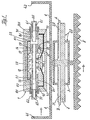
- the drawings show a hydraulic piston-cylinder unit 2.3 with control valve for Drive of mower blades.
- the unit consists of a mechanically actuated directional control valve 1, which is locked self-locking in the two working positions.
- the housing 1.0 of the Directional valve 1 and the piston rods of the hydraulic piston-cylinder unit are on Attached frame of the cutting unit.
- the cylinder 3 with the operating bracket 4 is connected to the Mower blade 5 connected.
- At the mower blade 5 can be more hydraulic Be arranged piston-cylinder units, which supplies from one and the same directional control valve become.
- the hydraulic piston-cylinder units are then interconnected connected in parallel. From this, the force is applied evenly at several points.
- the aperture 1.4, the bore 1.5 and the force of the spring 1.3 designed to be correspondingly large. Taking into account rest-forces a plurality of resilient balls may be arranged on the circumference. Because during the Insertion movement of the sleeve 6.2 to the left a change in volume occurs in the housing are both sides connected via a compensation line 12 right to the tank and the piston 1.1 is drilled hollow.
- the catch is shown graphically as a ball, it can also be used other detent bodies become.
- Control valve for switching a hydraulic piston-cylinder unit for the Drive a cutting blade on combine harvesters
Landscapes
- Life Sciences & Earth Sciences (AREA)
- Environmental Sciences (AREA)
- Fluid-Pressure Circuits (AREA)
- Actuator (AREA)
- Harvester Elements (AREA)
- Fluid-Driven Valves (AREA)
- Lifting Devices For Agricultural Implements (AREA)
- Reciprocating Pumps (AREA)
- Apparatuses For Generation Of Mechanical Vibrations (AREA)
Description
- Figur 1
- instilisierter Form einen Mähbalken beziehungsweise Mähmesser in Verbindung mit dem erfindungsgemäßen Steuerventil in einer Endstellung und
- Figur 2
- das in Figur 1 dargestellte Steuerventil in seiner anderen möglichen Endstellung, ebenfalls in Verbindung mit einer Mäheinrichtung.
- 1
- Wegeventil
- 1.0
- Ventilgehäuse
- 1.1
- Ventilkolben
- 1.2
- Raste
- 1.3
- Feder
- 1.4
- Blende
- 1.5
- Kugelbohrung/Bohrung
- 1.6
- zentrale Durchgangsbohrung
- 1.7
- Nut
- 1.8
- Nut
- 2
- Kolbenstangen
- 2.1
- Bohrung
- 2.2
- Bohrung
- 2.3
- hydraulische Kolben-Zylinder-Einheit
- 3
- Zylinder
- 4
- Betätigungsbügel
- 4.1
- Bügelende
- 4.2
- Bügelende
- 5
- Mähmesser
- 6.1
- Hülse
- 6.2
- Hülse
- 6.5
- Deckel
- 7.1
- Druckfedern
- 8.1
- Stößel
- 8.2
- Stößel
- 9.1
- Ringnut
- 9.2
- Steuerleitung
- 10.1
- Ringnut
- 11.1
- Steuerkanal/Kanal
- A
- Anschluß
- B
- Leitung/Druckölzuführ
- T
- Tank
- Z1
- Zylinderraum
- Z2
- Zylinderraum
Claims (13)
- Steuerventil mit einem Gehäuse (1) und in der zentralen Durchgangsbohrung (1.6) des Gehäuses gelagertem axial verschiebbaren Ventilkolben (1.1) zum Umschalten einer hydraulischen Kolben-Zylinder-Einheit (2.3) für den oszillierenden Antrieb einer Arbeitseinheit einer landwirtschaftlichen Erntemaschine, insbesondere des Mähmessers (5) bei einem selbstfahrenden Mähdrescher, wobei die hydraulische Kolben-Zylinder-Einheit (2.3) einerseits mit der Arbeitseinheit und andererseits mit der Arbeitsmaschine verbunden ist,
dadurch gekennzeichnet, dass dem Ventilkolben (1.1) im Bereich seiner beiden Enden jeweils ein Steuerschieber zugeordnet ist, welche wechselweise von dem mit der Arbeitseinheit (5) verbundenen Teil der hydraulischen Kolben-Zylinder-Einheit (2.3) im Gehäuse mechanisch axial verschiebbar sind. - Steuerventil nach Anspruch 1,
dadurch gekennzeichnet, dass die Steuerschieber aus je einem Stößel (8.1) und (8.2) und je einer diese mit Spiel umgreifenden Hülse (6.1) und (6.2) bestehen, wobei sich an den dem Ventilkolben (1.1) abgewandten Ende der Stößel (8.1) und (8.2) einerseits und an den äußeren Enden der Hülsen (6.1) und (6.2) andererseits je eine Druckfeder (7.1) abstützen und dass die Hülsen (6.1) und (6.2) wechselweise über die Druckfedern (7.1) auf die Stößel (8.1) und (8.2) einwirken, die ihrerseits den Ventilkolben (1.1) wechselweise verschieben. - Steuerventil nach den Ansprüchen 1 und 2,
dadurch gekennzeichnet, dass der Ventilkolben (1.1) in jeder seiner beiden Schaltstellungen mittels einer federbelasteten Raste (1.2) sperrbar ist. - Steuerventil nach Anspruch 3,
dadurch gekennzeichnet, dass der Ventilkolben (1.1) zwei mit den jeweiligen Schaltstellungen entsprechendem Abstand aneinanderangeordnete Nuten (1.7) und (1.8) versehen ist, wobei je nach Schaltstellung des Ventilkolbens (1.1) in eine der beiden Nuten eine Raste (1.2) mittels einer Feder (1.3) teilweise eingedrückt ist und dass sowohl die Feder (1.3) als auch die Raste (1.2) in einer von der zentralen Durchgangsbohrung (1.6) des Gehäuses (1) radial nach außen geführten Bohrung (1.5) gehalten sind. - Steuerventil nach den Ansprüchen 1 bis 4,
dadurch gekennzeichnet, dass die Hülsen (6.1) und (6.2) an ihren äußeren Enden mit Deckeln (6.5) geschlossen sind, gegen die sich die Druckfedern (7.1) einendig abstützen. - Steuerventil nach einem oder mehreren der Ansprüche 1 bis 5,
dadurch gekennzeichnet, dass jeweils die Nut (1.7) oder (1.8), in der die Raste (1.2) eingerastet ist, über einen Kanal (11.1) zum Zwecke des Lösens der Raste mit Drucköl beaufschlagbar ist. - Steuerventil nach einem oder mehreren der Ansprüche 1 bis 6,
dadurch gekennzeichnet, dass durch das mechanische Verschieben einer Hülse (6.1) oder (6.2) einerseits der Ölstrom zu der Nut (1.7) beziehungsweise (1.8) freigegeben wird, in der die Raste (1.2) eingerastet ist und andererseits die Feder (7.1) vorgespannt wird, die auf den zugehörigen Stößel (8.1) oder (8.2) einwirkt zum Zwecke des Verschiebens des Ventilkolbens (1.1) nach dem Lösen der Raste (1.2). - Steuerventil nach einem oder mehreren der Ansprüche 1 bis 7,
dadurch gekennzeichnet, dass in den Kanal (11.1) eine Blende (1.4) eingebaut ist. - Steuerventil nach einem oder mehreren der Ansprüche 1 bis 8,
dadurch gekennzeichnet, dass die Nuten (1.7) und (1.8) schräg zum Nutgrund hin verlaufende Flächen aufweisen zwecks genauer Definition jeweils einer Schaltstellung des Ventilkolbens (1.1) durch die federbelastete Raste (1.2). - Steuerventil nach einem oder mehreren der Ansprüche 1 bis 9,
dadurch gekennzeichnet, dass der Zylinder (3) der hydraulischen Kolben-Zylinder-Einheit sowohl mit dem Mähmesser (5) als auch mit einem Bügel (4) verbunden ist, dessen frei auslaufende Enden (4.1) beziehungsweise (4.2) Betätigungsanschläge für die Hülsen (6.1) beziehungsweise (6.2) bilden. - Steuerventil nach einem oder mehreren der Ansprüche 1 bis 10,
dadurch gekennzeichnet, dass die Kolbenstangen (2) der hydraulischen Kolben-Zylinder-Einheit (2.3) rahmenfest und mit Axialbohrungen (2.1) und (2.2) versehen sind, die jeweils zu einer Zylinderseite des Kolbens führen. - Steuerventil nach einem oder mehreren der Ansprüche 1 bis 11,
dadurch gekennzeichnet, dass jeweils nach Schaltstellung des Ventilkolbens (1.1) eine der Axialbohrungen (2.1) oder (2.2) mit der Druckölzufuhr (B) und eine mit der Tankrückleitung (T) verbunden ist. - Steuerventil nach einem oder mehreren der Ansprüche 1 bis 12,
dadurch gekennzeichnet, dass die die beiden Zylinderräume (Z1) und (Z2), die von dem Ventilkolben (1.1) einerseits und den Steuerschiebern (6.1) und (8.1) beziehungsweise (6.2) und (8.2) begrenzt werden und Teile der Zentralbohrung (1.6) sind, miteinander über den Kanal (11.1) verbunden sind.
Priority Applications (1)
| Application Number | Priority Date | Filing Date | Title |
|---|---|---|---|
| DK01110306T DK1153536T3 (da) | 2000-05-12 | 2001-04-26 | Styreventil til omkobling af en hydrauliskstempel-cylinder-enhed til driften af en oscillerende maskindel |
Applications Claiming Priority (2)
| Application Number | Priority Date | Filing Date | Title |
|---|---|---|---|
| DE10023340A DE10023340A1 (de) | 2000-05-12 | 2000-05-12 | Steuerventil zum Umschalten einer hydraulischen Kolben-Zylinder-Einheit für den Antrieb eines oszillierenden Maschinenteils |
| DE10023340 | 2000-05-12 |
Publications (2)
| Publication Number | Publication Date |
|---|---|
| EP1153536A1 EP1153536A1 (de) | 2001-11-14 |
| EP1153536B1 true EP1153536B1 (de) | 2005-03-09 |
Family
ID=7641828
Family Applications (1)
| Application Number | Title | Priority Date | Filing Date |
|---|---|---|---|
| EP01110306A Expired - Lifetime EP1153536B1 (de) | 2000-05-12 | 2001-04-26 | Steuerventil zum Umschalten einer hydraulischen Kolben-Zylinder-Einheit für den Antrieb eines oszillierenden Maschinenteils |
Country Status (8)
| Country | Link |
|---|---|
| US (1) | US6557332B2 (de) |
| EP (1) | EP1153536B1 (de) |
| AT (1) | ATE290305T1 (de) |
| BR (1) | BR0101949B1 (de) |
| DE (2) | DE10023340A1 (de) |
| DK (1) | DK1153536T3 (de) |
| RU (1) | RU2267661C2 (de) |
| UA (1) | UA71931C2 (de) |
Families Citing this family (6)
| Publication number | Priority date | Publication date | Assignee | Title |
|---|---|---|---|---|
| WO2006014514A2 (en) * | 2004-07-08 | 2006-02-09 | Burns Sr Patrick J | Fluid power unit having closed circuit |
| US7658059B2 (en) * | 2007-06-04 | 2010-02-09 | Crary Industries, Inc. | Synchronous drive for split sickle bars on harvester header |
| PH12012501135A1 (en) | 2011-11-10 | 2012-11-05 | Univ Case Western Reserve | Insulin analogues with chlorinated amino acids |
| CN104838081B (zh) | 2013-02-26 | 2017-04-19 | 哈利伯顿能源服务公司 | 井下工具的远程液压控制 |
| US10443349B2 (en) | 2015-04-15 | 2019-10-15 | Halliburton Energy Services, Inc. | Remote hydraulic control of downhole tools |
| US11903338B2 (en) * | 2021-02-16 | 2024-02-20 | Moline, IL | Systems and methods for reciprocating a cutter of an agricultural harvesting head |
Family Cites Families (20)
| Publication number | Priority date | Publication date | Assignee | Title |
|---|---|---|---|---|
| US2569507A (en) * | 1945-10-27 | 1951-10-02 | Schlegell Frederick Von | Hydraulic operating system for mowing machines |
| US2484861A (en) * | 1947-12-09 | 1949-10-18 | Ernest L Stewart | Fluid pressure sickle drive for harvesters |
| US2588002A (en) * | 1948-03-26 | 1952-03-04 | Earl W Holmes | Hydraulically operated mobile weed and brush cutter |
| US2588003A (en) * | 1948-03-26 | 1952-03-04 | Hall Machine And Iron Works In | Hydraulically operated reciprocating sickle mechanism |
| US2917026A (en) * | 1955-04-01 | 1959-12-15 | Curtiss Wright Corp | Fast action hydraulic valve |
| FR1214426A (fr) * | 1958-12-01 | 1960-04-08 | Mode d'actionnement des outils et matériels traînés ou portés par tracteurs ou autres moyens mécaniques | |
| DE1407153A1 (de) * | 1959-09-04 | 1968-11-21 | Linde Ag | Hydraulische Energieuebertragung fuer Antriebe mit drehender oder hin- und hergehender Bewegung |
| DE1904778A1 (de) * | 1969-01-31 | 1970-08-20 | Koeppern & Co Kg Maschf | Hydraulischer Vibrationsantrieb |
| US3823534A (en) * | 1973-02-16 | 1974-07-16 | Int Harvester Co | Sickle bar mower and drive therefor |
| US4020744A (en) * | 1974-11-13 | 1977-05-03 | Raymond International Inc. | Control of hydraulically powered equipment |
| US4280396A (en) * | 1978-05-18 | 1981-07-28 | Control Concepts, Inc. | Hydraulic oscillator |
| DE2904293A1 (de) * | 1979-02-05 | 1980-08-07 | Claas Ohg | Hydraulisches steuerventil |
| FR2453306B1 (fr) * | 1979-04-06 | 1986-03-14 | Dba | Dispositif d'actionnement hydraulique a cinq positions |
| US4402174A (en) * | 1981-07-02 | 1983-09-06 | Allis-Chalmers Corporation | Sickle drive with resonant spring on the nondriven end of the sickle |
| DE3150252A1 (de) * | 1981-12-18 | 1983-06-30 | Vereinigte Flugtechnische Werke Gmbh, 2800 Bremen | Schaltventil fuer hydraulische stellglieder |
| DE8209146U1 (de) | 1982-03-31 | 1983-04-21 | K. u. K. Mähtechnik GmbH, 3012 Langenhagen | Mähantrieb für eine Mähvorrichtung |
| DE3344967C1 (de) * | 1983-12-13 | 1985-04-25 | Gerhard Dücker KG Landmaschinenfabrik, 4424 Stadtlohn | Anbauarbeitsgerät |
| SU1710872A1 (ru) * | 1989-02-28 | 1992-02-07 | Markhaj Vladislav V | Распределитель |
| DE19529067C2 (de) | 1995-08-08 | 1998-07-16 | Claas Ohg | Vorsatzgerät für eine Halmguterntemaschine |
| US5787786A (en) * | 1996-05-09 | 1998-08-04 | Sauer-Sundstrand - Control Concepts | Dual hydraulic oscillator for the reciprocating cutter of an agricultural machine |
-
2000
- 2000-05-12 DE DE10023340A patent/DE10023340A1/de not_active Withdrawn
-
2001
- 2001-04-26 DK DK01110306T patent/DK1153536T3/da active
- 2001-04-26 DE DE50105509T patent/DE50105509D1/de not_active Expired - Lifetime
- 2001-04-26 EP EP01110306A patent/EP1153536B1/de not_active Expired - Lifetime
- 2001-04-26 AT AT01110306T patent/ATE290305T1/de not_active IP Right Cessation
- 2001-05-07 UA UA2001053133A patent/UA71931C2/uk unknown
- 2001-05-10 RU RU2001113667/06A patent/RU2267661C2/ru not_active IP Right Cessation
- 2001-05-11 BR BRPI0101949-0A patent/BR0101949B1/pt not_active IP Right Cessation
- 2001-08-30 US US09/854,341 patent/US6557332B2/en not_active Expired - Fee Related
Also Published As
| Publication number | Publication date |
|---|---|
| US20020005113A1 (en) | 2002-01-17 |
| DK1153536T3 (da) | 2005-06-27 |
| RU2267661C2 (ru) | 2006-01-10 |
| DE10023340A1 (de) | 2001-11-15 |
| BR0101949B1 (pt) | 2010-11-30 |
| EP1153536A1 (de) | 2001-11-14 |
| BR0101949A (pt) | 2001-12-18 |
| DE50105509D1 (de) | 2005-04-14 |
| US6557332B2 (en) | 2003-05-06 |
| ATE290305T1 (de) | 2005-03-15 |
| UA71931C2 (uk) | 2005-01-17 |
Similar Documents
| Publication | Publication Date | Title |
|---|---|---|
| DE102014206460B3 (de) | Umschaltbare hydrostatische Verstelleinrichtung und zugehöriger Steuerkolben | |
| DE1576088B2 (de) | Schnellentlastungsventil fuer hydraulische kraftzylinder | |
| DE7702999U1 (de) | Ventilanordnung in einer hydraulischen steuervorrichtung fuer ein fahrzeug- wechselwendegetriebe | |
| WO2017140499A1 (de) | Gleichgangzylinder für strangpressanlagen | |
| DE2419654A1 (de) | In zwei richtungen arbeitendes koaxialventil als steuerungs- und entlastungsorgan fuer stroemungen, insbesondere in hydrostatischen getrieben | |
| DE1806264B2 (de) | Antriebsvorrichtung zum betaetigen von zwei antriebsmotoren durch druckmittel | |
| DE102007007288A1 (de) | Antriebsvorrichtung, insbesondere für ein bewegbares Bauteil an einer Kunststoffspritzgieß- oder einer Blasformmaschine | |
| DE69701300T2 (de) | Hydraulisches Versorgungssystem für Holzspalter | |
| EP3698051B1 (de) | Wechselschaltende hydraulikeinheit | |
| EP1153536A1 (de) | Steuerventil zum Umschalten einer hydraulischen Kolben-Zylinder-Einheit für den Antrieb eines oszillierenden Maschinenteils | |
| DE102013207299B4 (de) | Hydraulisches Wegeventil für das Hubwerk eines landwirtschaftlichen Fahrzeugs | |
| DE102014115029A1 (de) | Hydraulisches Steuerventil | |
| DE3421582A1 (de) | Schalteinrichtung fuer ein unsynchronisiertes zahnrad-wechselgetriebe | |
| DE1530903B1 (de) | Schaltvorrichtung für Fahrzeugwechselgetriebe | |
| DE675501C (de) | Druckmittelschaltvorrichtung fuer Zahnraederwechselgetriebe, insbesondere von Kraftfahrzeugen | |
| EP1184576B1 (de) | Ventileinrichtung | |
| DE2926817A1 (de) | Steuervorrichtung fuer ein schaltgetriebe im antrieb eines funktionsteils einer erntemaschine | |
| EP1239208B1 (de) | Elektro-hydraulischer Schaltungskreis zur Druckentlastung von Schnellkupplungen | |
| DE1000624B (de) | Steuerung mengenveraenderlicher Pumpen, insbesondere fuer hydraulische Kraftheber | |
| DE2450330C3 (de) | Doppelhydraulischer Stellantrieb | |
| DE899138C (de) | Hydraulische Steuerung fuer Schaltraedergetriebe von Werkzeugmaschinen | |
| DE102021107375B4 (de) | Vorrichtung zum Antreiben einer Messerschiene eines Mähwerks, Mähkorb und Verfahren zum Betreiben eines Mähwerks | |
| DE1935253A1 (de) | Hydraulisch oder pneumatisch angetriebener Vibrationsantrieb | |
| EP0090879A1 (de) | Hydraulische Antriebseinrichtung für landwirtschaftliches Arbeitsgerät | |
| DE1122312B (de) | Steuervorrichtung zum wahlweisen Schalten mehrerer hydraulischer Arbeitszylinder an landwirtschaftlichen Maschinen, insbesondere Wurzelfruchterntemaschinen |
Legal Events
| Date | Code | Title | Description |
|---|---|---|---|
| PUAI | Public reference made under article 153(3) epc to a published international application that has entered the european phase |
Free format text: ORIGINAL CODE: 0009012 |
|
| AK | Designated contracting states |
Kind code of ref document: A1 Designated state(s): AT BE CH CY DE DK ES FI FR GB GR IE IT LI LU MC NL PT SE TR |
|
| AX | Request for extension of the european patent |
Free format text: AL;LT;LV;MK;RO;SI |
|
| 17P | Request for examination filed |
Effective date: 20020514 |
|
| AKX | Designation fees paid |
Free format text: AT BE CH CY DE DK ES FI FR GB GR IE IT LI LU MC NL PT SE TR |
|
| 17Q | First examination report despatched |
Effective date: 20031128 |
|
| GRAP | Despatch of communication of intention to grant a patent |
Free format text: ORIGINAL CODE: EPIDOSNIGR1 |
|
| GRAS | Grant fee paid |
Free format text: ORIGINAL CODE: EPIDOSNIGR3 |
|
| GRAA | (expected) grant |
Free format text: ORIGINAL CODE: 0009210 |
|
| AK | Designated contracting states |
Kind code of ref document: B1 Designated state(s): AT BE CH CY DE DK ES FI FR GB GR IE IT LI LU MC NL PT SE TR |
|
| PG25 | Lapsed in a contracting state [announced via postgrant information from national office to epo] |
Ref country code: NL Free format text: LAPSE BECAUSE OF FAILURE TO SUBMIT A TRANSLATION OF THE DESCRIPTION OR TO PAY THE FEE WITHIN THE PRESCRIBED TIME-LIMIT Effective date: 20050309 Ref country code: IE Free format text: LAPSE BECAUSE OF FAILURE TO SUBMIT A TRANSLATION OF THE DESCRIPTION OR TO PAY THE FEE WITHIN THE PRESCRIBED TIME-LIMIT Effective date: 20050309 Ref country code: FI Free format text: LAPSE BECAUSE OF FAILURE TO SUBMIT A TRANSLATION OF THE DESCRIPTION OR TO PAY THE FEE WITHIN THE PRESCRIBED TIME-LIMIT Effective date: 20050309 Ref country code: GB Free format text: LAPSE BECAUSE OF FAILURE TO SUBMIT A TRANSLATION OF THE DESCRIPTION OR TO PAY THE FEE WITHIN THE PRESCRIBED TIME-LIMIT Effective date: 20050309 Ref country code: TR Free format text: LAPSE BECAUSE OF FAILURE TO SUBMIT A TRANSLATION OF THE DESCRIPTION OR TO PAY THE FEE WITHIN THE PRESCRIBED TIME-LIMIT Effective date: 20050309 |
|
| REG | Reference to a national code |
Ref country code: GB Ref legal event code: FG4D Free format text: NOT ENGLISH |
|
| REG | Reference to a national code |
Ref country code: CH Ref legal event code: EP |
|
| REG | Reference to a national code |
Ref country code: IE Ref legal event code: FG4D Free format text: GERMAN |
|
| REF | Corresponds to: |
Ref document number: 50105509 Country of ref document: DE Date of ref document: 20050414 Kind code of ref document: P |
|
| PG25 | Lapsed in a contracting state [announced via postgrant information from national office to epo] |
Ref country code: LU Free format text: LAPSE BECAUSE OF NON-PAYMENT OF DUE FEES Effective date: 20050426 Ref country code: CY Free format text: LAPSE BECAUSE OF FAILURE TO SUBMIT A TRANSLATION OF THE DESCRIPTION OR TO PAY THE FEE WITHIN THE PRESCRIBED TIME-LIMIT Effective date: 20050426 |
|
| PG25 | Lapsed in a contracting state [announced via postgrant information from national office to epo] |
Ref country code: CH Free format text: LAPSE BECAUSE OF NON-PAYMENT OF DUE FEES Effective date: 20050430 Ref country code: LI Free format text: LAPSE BECAUSE OF NON-PAYMENT OF DUE FEES Effective date: 20050430 Ref country code: MC Free format text: LAPSE BECAUSE OF NON-PAYMENT OF DUE FEES Effective date: 20050430 |
|
| PG25 | Lapsed in a contracting state [announced via postgrant information from national office to epo] |
Ref country code: GR Free format text: LAPSE BECAUSE OF FAILURE TO SUBMIT A TRANSLATION OF THE DESCRIPTION OR TO PAY THE FEE WITHIN THE PRESCRIBED TIME-LIMIT Effective date: 20050609 |
|
| PG25 | Lapsed in a contracting state [announced via postgrant information from national office to epo] |
Ref country code: ES Free format text: LAPSE BECAUSE OF FAILURE TO SUBMIT A TRANSLATION OF THE DESCRIPTION OR TO PAY THE FEE WITHIN THE PRESCRIBED TIME-LIMIT Effective date: 20050620 |
|
| REG | Reference to a national code |
Ref country code: DK Ref legal event code: T3 |
|
| NLV1 | Nl: lapsed or annulled due to failure to fulfill the requirements of art. 29p and 29m of the patents act | ||
| PG25 | Lapsed in a contracting state [announced via postgrant information from national office to epo] |
Ref country code: PT Free format text: LAPSE BECAUSE OF FAILURE TO SUBMIT A TRANSLATION OF THE DESCRIPTION OR TO PAY THE FEE WITHIN THE PRESCRIBED TIME-LIMIT Effective date: 20050907 |
|
| GBV | Gb: ep patent (uk) treated as always having been void in accordance with gb section 77(7)/1977 [no translation filed] |
Effective date: 20050309 |
|
| REG | Reference to a national code |
Ref country code: IE Ref legal event code: FD4D |
|
| REG | Reference to a national code |
Ref country code: CH Ref legal event code: PL |
|
| ET | Fr: translation filed | ||
| PLBE | No opposition filed within time limit |
Free format text: ORIGINAL CODE: 0009261 |
|
| STAA | Information on the status of an ep patent application or granted ep patent |
Free format text: STATUS: NO OPPOSITION FILED WITHIN TIME LIMIT |
|
| 26N | No opposition filed |
Effective date: 20051212 |
|
| PG25 | Lapsed in a contracting state [announced via postgrant information from national office to epo] |
Ref country code: SE Free format text: LAPSE BECAUSE OF FAILURE TO SUBMIT A TRANSLATION OF THE DESCRIPTION OR TO PAY THE FEE WITHIN THE PRESCRIBED TIME-LIMIT Effective date: 20050609 |
|
| PGFP | Annual fee paid to national office [announced via postgrant information from national office to epo] |
Ref country code: AT Payment date: 20090416 Year of fee payment: 9 |
|
| PG25 | Lapsed in a contracting state [announced via postgrant information from national office to epo] |
Ref country code: AT Free format text: LAPSE BECAUSE OF NON-PAYMENT OF DUE FEES Effective date: 20100426 |
|
| REG | Reference to a national code |
Ref country code: FR Ref legal event code: PLFP Year of fee payment: 15 |
|
| PGFP | Annual fee paid to national office [announced via postgrant information from national office to epo] |
Ref country code: DK Payment date: 20150420 Year of fee payment: 15 |
|
| PGFP | Annual fee paid to national office [announced via postgrant information from national office to epo] |
Ref country code: FR Payment date: 20150421 Year of fee payment: 15 Ref country code: IT Payment date: 20150430 Year of fee payment: 15 |
|
| PGFP | Annual fee paid to national office [announced via postgrant information from national office to epo] |
Ref country code: DE Payment date: 20160309 Year of fee payment: 16 |
|
| PGFP | Annual fee paid to national office [announced via postgrant information from national office to epo] |
Ref country code: BE Payment date: 20160420 Year of fee payment: 16 |
|
| REG | Reference to a national code |
Ref country code: DK Ref legal event code: EBP Effective date: 20160430 |
|
| REG | Reference to a national code |
Ref country code: FR Ref legal event code: ST Effective date: 20161230 |
|
| PG25 | Lapsed in a contracting state [announced via postgrant information from national office to epo] |
Ref country code: FR Free format text: LAPSE BECAUSE OF NON-PAYMENT OF DUE FEES Effective date: 20160502 |
|
| PG25 | Lapsed in a contracting state [announced via postgrant information from national office to epo] |
Ref country code: IT Free format text: LAPSE BECAUSE OF NON-PAYMENT OF DUE FEES Effective date: 20160426 |
|
| PG25 | Lapsed in a contracting state [announced via postgrant information from national office to epo] |
Ref country code: DK Free format text: LAPSE BECAUSE OF NON-PAYMENT OF DUE FEES Effective date: 20160430 |
|
| REG | Reference to a national code |
Ref country code: DE Ref legal event code: R119 Ref document number: 50105509 Country of ref document: DE |
|
| PG25 | Lapsed in a contracting state [announced via postgrant information from national office to epo] |
Ref country code: DE Free format text: LAPSE BECAUSE OF NON-PAYMENT OF DUE FEES Effective date: 20171103 |
|
| REG | Reference to a national code |
Ref country code: BE Ref legal event code: MM Effective date: 20170430 |
|
| PG25 | Lapsed in a contracting state [announced via postgrant information from national office to epo] |
Ref country code: BE Free format text: LAPSE BECAUSE OF NON-PAYMENT OF DUE FEES Effective date: 20170430 |