EP1152134A2 - Sekundärluftgebläse für eine Brennkraftmaschine - Google Patents
Sekundärluftgebläse für eine Brennkraftmaschine Download PDFInfo
- Publication number
- EP1152134A2 EP1152134A2 EP01103300A EP01103300A EP1152134A2 EP 1152134 A2 EP1152134 A2 EP 1152134A2 EP 01103300 A EP01103300 A EP 01103300A EP 01103300 A EP01103300 A EP 01103300A EP 1152134 A2 EP1152134 A2 EP 1152134A2
- Authority
- EP
- European Patent Office
- Prior art keywords
- air
- unit
- housing
- mass sensor
- electronics unit
- Prior art date
- Legal status (The legal status is an assumption and is not a legal conclusion. Google has not performed a legal analysis and makes no representation as to the accuracy of the status listed.)
- Granted
Links
Images

Classifications
-
- F—MECHANICAL ENGINEERING; LIGHTING; HEATING; WEAPONS; BLASTING
- F01—MACHINES OR ENGINES IN GENERAL; ENGINE PLANTS IN GENERAL; STEAM ENGINES
- F01N—GAS-FLOW SILENCERS OR EXHAUST APPARATUS FOR MACHINES OR ENGINES IN GENERAL; GAS-FLOW SILENCERS OR EXHAUST APPARATUS FOR INTERNAL-COMBUSTION ENGINES
- F01N3/00—Exhaust or silencing apparatus having means for purifying, rendering innocuous, or otherwise treating exhaust
- F01N3/08—Exhaust or silencing apparatus having means for purifying, rendering innocuous, or otherwise treating exhaust for rendering innocuous
- F01N3/10—Exhaust or silencing apparatus having means for purifying, rendering innocuous, or otherwise treating exhaust for rendering innocuous by thermal or catalytic conversion of noxious components of exhaust
- F01N3/24—Exhaust or silencing apparatus having means for purifying, rendering innocuous, or otherwise treating exhaust for rendering innocuous by thermal or catalytic conversion of noxious components of exhaust characterised by constructional aspects of converting apparatus
- F01N3/30—Arrangements for supply of additional air
- F01N3/32—Arrangements for supply of additional air using air pump
-
- Y—GENERAL TAGGING OF NEW TECHNOLOGICAL DEVELOPMENTS; GENERAL TAGGING OF CROSS-SECTIONAL TECHNOLOGIES SPANNING OVER SEVERAL SECTIONS OF THE IPC; TECHNICAL SUBJECTS COVERED BY FORMER USPC CROSS-REFERENCE ART COLLECTIONS [XRACs] AND DIGESTS
- Y02—TECHNOLOGIES OR APPLICATIONS FOR MITIGATION OR ADAPTATION AGAINST CLIMATE CHANGE
- Y02T—CLIMATE CHANGE MITIGATION TECHNOLOGIES RELATED TO TRANSPORTATION
- Y02T10/00—Road transport of goods or passengers
- Y02T10/10—Internal combustion engine [ICE] based vehicles
- Y02T10/12—Improving ICE efficiencies
Definitions
- the invention relates to a secondary air blower for an internal combustion engine a housing in which a motor unit and one by the motor unit driven pump unit are arranged, the housing one Has air inlet duct and an air outlet duct, with an air mass sensor, which is arranged in one of these channels and via an electronic unit Motor unit controls.
- the secondary air blower serves to use up unused fuel in the cold start phase Blow in fresh air into the exhaust gas and in this way the To minimize pollutant emissions.
- the air mass sensor supplies the actual value of the air mass flow and forwards this actual value to the electronics unit, the one with the motor of the secondary air blower and the other with a higher-level computer unit, for example an engine control unit connected is.
- the disadvantage of this known embodiment are Wiring from the air mass sensor and from the blower motor to Electronics unit, since the cabling requires more assembly cause and are also prone to interference. Also needed the electronics unit space.
- the invention is based on the object To create secondary air blower that avoids the disadvantages mentioned above.
- the air mass sensor is arranged on the electronics unit, the electronics unit on the Housing and / or the air inlet or air outlet channel is fixed.
- the electronics unit is automatically cooled instead of. It is particularly advantageous if the parts to be cooled Electronics unit seen in the flow direction behind the air mass sensor are attached, because in this way the air mass flow through the Heat exchange is affected.
- the electronics unit does not need another one Installation space through the attachment according to the invention.
- FIG. 1 shows a side view of the secondary air blower 1 according to the invention.
- a housing 2 of the secondary air blower 1 does not have one in a known manner Motor unit shown, and a driven by the motor unit Pump unit on. Furthermore, the housing has an air inlet duct 3, and an air outlet duct 4.
- An electronics unit 5 is now on the housing 2, for example by gluing fixed on which an air mass sensor 6 is arranged such that the Air mass sensor 6 extends into the air inlet duct 3.
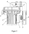
- FIG. 2 shows a second embodiment of the invention Secondary air blower 1.
- the electronics unit 5 with the Air mass sensor 6 is only arranged on the air inlet duct 3, whereby the angled course of the air inlet duct 3, the electronics unit uses space created between the housing 2 and air inlet duct 3.
- the electronics unit 5 with the motor unit is connected via an external cable 7 of the secondary air blower connected.
Landscapes
- Chemical & Material Sciences (AREA)
- Engineering & Computer Science (AREA)
- Chemical Kinetics & Catalysis (AREA)
- Health & Medical Sciences (AREA)
- Toxicology (AREA)
- Combustion & Propulsion (AREA)
- Mechanical Engineering (AREA)
- General Engineering & Computer Science (AREA)
- Exhaust Gas After Treatment (AREA)
Abstract
Description
- Figur 1
- eine Seitenansicht eines ersten Ausführungsbeispiels der Erfindung mit teilweise aufgebrochenen Luftkanal,
- Figur 2
- ein zweites Ausführungsbeispiel mit teilweise aufgebrochenen Luftkanal.
Claims (2)
- Sekundärluftgebläse für eine Brennkraftmaschine mit einem Gehäuse in dem eine Motoreinheit und eine durch die Motoreinheit angetriebene Pumpeneinheit angeordnet sind, wobei das Gehäuse einen Lufteinlaßkanal und einen Luftauslaßkanal aufweist, mit einem Luftmassensensor, der in einem dieser Kanäle angeordnet ist und über eine Elektronikeinheit die Motoreinheit regelt, dadurch gekennzeichnet, daß der Luftmassensensor (6) an der Elektronikeinheit (5) angeordnet ist, wobei die Elektronikeinheit (5) an dem Gehäuse (2) und/oder dem Lufteinlaß- (3) bzw. Luftauslaßkanal (4) fixiert ist.
- Sekundärluftgebläse nach Anspruch 1, dadurch gekennzeichnet, daß zu kühlende Teile der Elektronikeinheit (5) in Strömungsrichtung gesehen hinter dem Luftmassensensor (6) angeordnet sind.
Applications Claiming Priority (2)
| Application Number | Priority Date | Filing Date | Title |
|---|---|---|---|
| DE10022208 | 2000-05-06 | ||
| DE10022208A DE10022208A1 (de) | 2000-05-06 | 2000-05-06 | Sekundärluftgebläse für eine Brennkraftmaschine |
Publications (3)
| Publication Number | Publication Date |
|---|---|
| EP1152134A2 true EP1152134A2 (de) | 2001-11-07 |
| EP1152134A3 EP1152134A3 (de) | 2004-05-19 |
| EP1152134B1 EP1152134B1 (de) | 2005-12-21 |
Family
ID=7641084
Family Applications (1)
| Application Number | Title | Priority Date | Filing Date |
|---|---|---|---|
| EP01103300A Expired - Lifetime EP1152134B1 (de) | 2000-05-06 | 2001-02-13 | Sekundärluftgebläse für eine Brennkraftmaschine |
Country Status (3)
| Country | Link |
|---|---|
| US (1) | US6374610B2 (de) |
| EP (1) | EP1152134B1 (de) |
| DE (2) | DE10022208A1 (de) |
Families Citing this family (3)
| Publication number | Priority date | Publication date | Assignee | Title |
|---|---|---|---|---|
| US8857179B2 (en) * | 2011-03-23 | 2014-10-14 | Chrysler Group Llc | Secondary air system with variable speed air pump and multi-position gated check valve |
| GB2525664B (en) | 2014-05-01 | 2020-12-09 | Bamford Excavators Ltd | An air inlet system comprising a mass air flow sensor |
| DE102016103525A1 (de) | 2016-02-29 | 2017-08-31 | Pierburg Gmbh | Gebläse für einen Verbrennungsmotor |
Family Cites Families (8)
| Publication number | Priority date | Publication date | Assignee | Title |
|---|---|---|---|---|
| US4817387A (en) * | 1986-10-27 | 1989-04-04 | Hamilton C. Forman, Trustee | Turbocharger/supercharger control device |
| JP2622994B2 (ja) * | 1988-08-05 | 1997-06-25 | 株式会社いすゞセラミックス研究所 | 回転電機付ターボチャージャの制御装置 |
| US4955785A (en) * | 1988-12-05 | 1990-09-11 | Sundstrand Corporation | Fan structure with flow responsive switch mechanism |
| CH688105A5 (fr) * | 1993-02-03 | 1997-05-15 | Jose Murga | Ensemble pompe ou turbine à flux axial et machine électrique. |
| JP3642578B2 (ja) * | 1993-03-30 | 2005-04-27 | 株式会社荏原製作所 | ポンプ装置 |
| DE4440495A1 (de) * | 1994-11-12 | 1996-05-15 | Bosch Gmbh Robert | Elektrisch betriebene Luftgebläseeinheit, insbesondere Sekundärluftgebläseeinheit |
| JPH0953438A (ja) * | 1995-08-10 | 1997-02-25 | Toyota Autom Loom Works Ltd | 空気供給装置、内燃機関のパティキュレートフィルタ再生用の二次空気供給装置 |
| US5931144A (en) * | 1998-10-29 | 1999-08-03 | Firey; Joseph C. | Compensator for manifold fuel injectors |
-
2000
- 2000-05-06 DE DE10022208A patent/DE10022208A1/de not_active Withdrawn
-
2001
- 2001-02-13 DE DE50108423T patent/DE50108423D1/de not_active Expired - Fee Related
- 2001-02-13 EP EP01103300A patent/EP1152134B1/de not_active Expired - Lifetime
- 2001-05-04 US US09/849,301 patent/US6374610B2/en not_active Expired - Fee Related
Also Published As
| Publication number | Publication date |
|---|---|
| US20010037644A1 (en) | 2001-11-08 |
| DE10022208A1 (de) | 2001-11-08 |
| US6374610B2 (en) | 2002-04-23 |
| DE50108423D1 (de) | 2006-01-26 |
| EP1152134B1 (de) | 2005-12-21 |
| EP1152134A3 (de) | 2004-05-19 |
Similar Documents
| Publication | Publication Date | Title |
|---|---|---|
| DE3446950C1 (de) | Steuervorrichtung fuer die Kuehlluft luft-fluessigkeits-gekuehlter Brennkraftmaschinen,insbesondere von Kraftfahrzeugen | |
| DE2844340C2 (de) | Generator/Gebläse-Aggregat | |
| DE1926041B2 (de) | Abgas-nachverbrennungsanlage fuer brennkraftmaschinen | |
| DE3136673A1 (de) | Stark aufgeladene und mit luftkuehlungssystem ausgestattete brennkraftmaschine sowie kuehlungssystem fuer derartige brennkraftmaschinen | |
| EP0826868A1 (de) | Verfahren zur Abgasreinigung einer Brennkraftmaschine | |
| EP0535406A1 (de) | Kraftfahrzeug-Vorderbau | |
| DE60306717T2 (de) | Wärmeaustauscher für ein EGR System mit integrierter Bypassleitung | |
| DE19857577C2 (de) | Abgasrückführungssystem für eine Brennkraftmaschine | |
| DE2437232B2 (de) | Heizungs- bzw. klimaanlage fuer kraftfahrzeuge | |
| EP0908615B1 (de) | Abgasrückführventil | |
| DE60123881T2 (de) | Vorrichtung zur thermischen Regelung der Ansaugluft einer Brennkraftmaschine eines Kraftfahrzeuges | |
| DE60204993T2 (de) | Frischlufteinlassvorrichtung eines Luftfahrzeuges | |
| EP0807576B1 (de) | Ejektor-Ölkühlsystem für ein Flugzeug-Hilfstriebwerk | |
| EP1152134B1 (de) | Sekundärluftgebläse für eine Brennkraftmaschine | |
| DE19857578C2 (de) | Abgasrückführsystem für eine Brennkraftmaschine | |
| DE4439792A1 (de) | Lufteinlaßsystem für Verbrennungsmotoren | |
| DE10350521A1 (de) | Vorrichtung zur Abgasrückführung an Verbrennungskraftmaschinen | |
| EP1133623A1 (de) | Kühlkreislauf | |
| DE3501862C2 (de) | ||
| EP1213547B1 (de) | Motorunabhängiges Heizgerät eines Kraftfahrzeuges | |
| DE19857926B4 (de) | Ventilator für einen Verbrennungsmotor | |
| EP2848478A2 (de) | Flussumschalter | |
| DE19809412B4 (de) | Sauganlage zur Verbrennungsluftversorgung einer Brennkraftmaschine | |
| DE19834390C1 (de) | Luftführungsgehäuse | |
| DE10216386B4 (de) | Verwirbelungs-Einrichtung für einen Verbrennungsmotor |
Legal Events
| Date | Code | Title | Description |
|---|---|---|---|
| PUAI | Public reference made under article 153(3) epc to a published international application that has entered the european phase |
Free format text: ORIGINAL CODE: 0009012 |
|
| 17P | Request for examination filed |
Effective date: 20010213 |
|
| AK | Designated contracting states |
Kind code of ref document: A2 Designated state(s): AT BE CH CY DE DK ES FI FR GB GR IE IT LI LU MC NL PT SE TR |
|
| AX | Request for extension of the european patent |
Free format text: AL;LT;LV;MK;RO;SI |
|
| RAP1 | Party data changed (applicant data changed or rights of an application transferred) |
Owner name: PIERBURG GMBH |
|
| PUAL | Search report despatched |
Free format text: ORIGINAL CODE: 0009013 |
|
| AK | Designated contracting states |
Kind code of ref document: A3 Designated state(s): AT BE CH CY DE DK ES FI FR GB GR IE IT LI LU MC NL PT SE TR |
|
| AX | Request for extension of the european patent |
Extension state: AL LT LV MK RO SI |
|
| AKX | Designation fees paid |
Designated state(s): DE FR GB IT |
|
| GRAP | Despatch of communication of intention to grant a patent |
Free format text: ORIGINAL CODE: EPIDOSNIGR1 |
|
| GRAS | Grant fee paid |
Free format text: ORIGINAL CODE: EPIDOSNIGR3 |
|
| GRAA | (expected) grant |
Free format text: ORIGINAL CODE: 0009210 |
|
| AK | Designated contracting states |
Kind code of ref document: B1 Designated state(s): DE FR GB IT |
|
| REG | Reference to a national code |
Ref country code: GB Ref legal event code: FG4D Free format text: NOT ENGLISH |
|
| REF | Corresponds to: |
Ref document number: 50108423 Country of ref document: DE Date of ref document: 20060126 Kind code of ref document: P |
|
| GBT | Gb: translation of ep patent filed (gb section 77(6)(a)/1977) |
Effective date: 20060119 |
|
| PGFP | Annual fee paid to national office [announced via postgrant information from national office to epo] |
Ref country code: FR Payment date: 20060216 Year of fee payment: 6 |
|
| ET | Fr: translation filed | ||
| PLBE | No opposition filed within time limit |
Free format text: ORIGINAL CODE: 0009261 |
|
| STAA | Information on the status of an ep patent application or granted ep patent |
Free format text: STATUS: NO OPPOSITION FILED WITHIN TIME LIMIT |
|
| 26N | No opposition filed |
Effective date: 20060922 |
|
| GBPC | Gb: european patent ceased through non-payment of renewal fee |
Effective date: 20070213 |
|
| REG | Reference to a national code |
Ref country code: FR Ref legal event code: ST Effective date: 20071030 |
|
| PG25 | Lapsed in a contracting state [announced via postgrant information from national office to epo] |
Ref country code: FR Free format text: LAPSE BECAUSE OF NON-PAYMENT OF DUE FEES Effective date: 20070228 Ref country code: GB Free format text: LAPSE BECAUSE OF NON-PAYMENT OF DUE FEES Effective date: 20070213 |
|
| PGFP | Annual fee paid to national office [announced via postgrant information from national office to epo] |
Ref country code: GB Payment date: 20060221 Year of fee payment: 6 |
|
| PGFP | Annual fee paid to national office [announced via postgrant information from national office to epo] |
Ref country code: DE Payment date: 20090428 Year of fee payment: 9 |
|
| PGFP | Annual fee paid to national office [announced via postgrant information from national office to epo] |
Ref country code: IT Payment date: 20100226 Year of fee payment: 10 |
|
| PG25 | Lapsed in a contracting state [announced via postgrant information from national office to epo] |
Ref country code: DE Free format text: LAPSE BECAUSE OF NON-PAYMENT OF DUE FEES Effective date: 20100901 |
|
| PG25 | Lapsed in a contracting state [announced via postgrant information from national office to epo] |
Ref country code: IT Free format text: LAPSE BECAUSE OF NON-PAYMENT OF DUE FEES Effective date: 20110213 |