EP1151894A2 - Rear view mirror, especially an exterior mirror for lorries - Google Patents
Rear view mirror, especially an exterior mirror for lorries Download PDFInfo
- Publication number
- EP1151894A2 EP1151894A2 EP01108074A EP01108074A EP1151894A2 EP 1151894 A2 EP1151894 A2 EP 1151894A2 EP 01108074 A EP01108074 A EP 01108074A EP 01108074 A EP01108074 A EP 01108074A EP 1151894 A2 EP1151894 A2 EP 1151894A2
- Authority
- EP
- European Patent Office
- Prior art keywords
- mirror arrangement
- arrangement according
- rearview mirror
- stiffening structure
- carrier
- Prior art date
- Legal status (The legal status is an assumption and is not a legal conclusion. Google has not performed a legal analysis and makes no representation as to the accuracy of the status listed.)
- Granted
Links
Images


Classifications
-
- B—PERFORMING OPERATIONS; TRANSPORTING
- B60—VEHICLES IN GENERAL
- B60R—VEHICLES, VEHICLE FITTINGS, OR VEHICLE PARTS, NOT OTHERWISE PROVIDED FOR
- B60R1/00—Optical viewing arrangements; Real-time viewing arrangements for drivers or passengers using optical image capturing systems, e.g. cameras or video systems specially adapted for use in or on vehicles
- B60R1/02—Rear-view mirror arrangements
- B60R1/06—Rear-view mirror arrangements mounted on vehicle exterior
- B60R1/0605—Rear-view mirror arrangements mounted on vehicle exterior specially adapted for mounting on trucks, e.g. by C-shaped support means
Definitions
- the invention relates to a rearview mirror arrangement especially as exterior mirrors for commercial vehicles according to the Preamble of claim 1.
- Such exterior mirrors are in a wide variety Constructions known from the prior art.
- a housing part that suitably with the body of the Vehicle is connected, is a mirror disc arranged by means of a swivel mechanism between you and the housing part adjustable relative to the housing is stored.
- the housing part itself is usually a Injection molded part made of solid plastic, mostly as a tub is formed in the other mirror components or appropriate attachment points are used.
- a supporting element for the outside mirror tube or Plate constructions used directly with the to the body leading mirror holder are connected such as this is known for example from EP-A-0 590 510.
- the Housing part then only serves to cover the Mirror disc back and the swivel mechanisms as well for aerodynamic covering of the exterior mirror.
- Such constructions are extremely complex and heavyweight.
- a very light construction, suitable for smaller Suitable mirror is known from DE 44 29 604 A1.
- the pipe construction was completely omitted and the foam part itself is a load-bearing structure educated. This is particularly the case with gradient foam in one piece or composed of several parts used.
- the carrier consists of a foam part, especially from gradient foam, in which a ramified Stiffening structure is embedded, on the one hand excellent stability and secondly a low one Vulnerability to vibration reached.
- a ramified Stiffening structure easier than the conventional structures with supports made of pipes or plates.
- the branched stiffening structure would be unsuitable as a carrier alone.
- the necessary Stability achieved. Because of the ramifications Stiffening structure a large surface on the Can attack foam part. This will become a carrier provided that made a stable composite structure Stiffening structure and surrounding foam part is.
- the branched stiffening structure is preferably is completely foamed in the gradient foam, i.e. the foam part is made in one piece. This will a particularly high stability and a special one permanent connection between foam part and branched Stiffening structure reached.
- the branched stiffening structure is preferably present from a truss structure, which from profiled rails is composed. Alternatively, there is a honeycomb structure possible as support structure. It is also possible to get a Perforated sheet structure as a branched support structure use.
- the main point of these stiffening structures is that a large outer or there is an inner surface on which the foam part can intervene and attack, creating the necessary hold and the necessary stability is achieved. This goal will also thereby achieved that the surface of the stiffening structure is additionally roughened and / or protrusions having.
- the carrier includes trough-shaped recesses in the or the mirrors and possibly associated pivoting mechanisms are embedded.
- fastening points on the stiffening structure for the different mirrors provided.
- the foam part is already foamed in a fitting part, by means of which the rearview mirror arrangement on the vehicle is attachable.
- This fitting part is in turn advantageously directly mechanically with the Stiffening structure connected.
- the fitting part also the joint for folding away the Outside mirror or for adjusting the mirror.
- the carrier can also be divided into two, with its two Parts are connected by a joint. Both Parts of the carrier are then ramified Stiffening structure and surrounding foam part built.
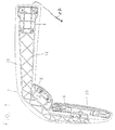
- Fig. 1 shows schematically a first embodiment of the Invention.
- the rearview mirror assembly includes one Carrier 2, the vehicle side with a fitting part 4th connected is.
- a first mirror 6 and a second mirror 8 mounted At the end of the Carrier 2 is a first mirror 6 and a second mirror 8 mounted. Both mirrors 6 and 8 comprise an adjustment mechanism 10 or 12 by means of which they are attached to the carrier 2 are mounted.
- the carrier 2 comprises a branched stiffening structure in the form of a truss structure 14, which in a foamed part 16 of gradient foam embedded is.
- the reference numeral 17 denotes the electrical Connections that are foamed into the gradient foam 16.
- the gradient foam 16 and the Truss structure 14 empty tubes, not shown provide in which the electrical connections 17 laid become.
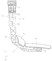
- Fig. 2 shows a detailed representation of the truss structure 14 with a first and a second holder 18 and 20 for the first and second mirrors 6 and 8.
- the fitting 4 is mechanical firmly with the stiffening structure or the truss structure 14 connected, more precisely screwed.
- the whole arrangement 2 consisting of truss structure 14 and Fitting part 4 is foamed or from which Gradient foam 16 surrounds and thus forms the composite carrier 2 according to the invention.
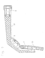
- FIG. 3 shows an illustration of the first Embodiment of the invention from above without foamed Part 16. From FIG. 2 it can be seen that the fitting part 4 is screwed to the truss structure 14.
- Fig. 4 shows a sectional view of the fitting part 4 from which it can be seen that the fitting part 4 a has a similar structure to the truss structure 14, so that it is fixed with the gradient foam 16 or with the foamed part 16 connects.
- FIG. 5 to 7 show a second embodiment of the Invention, which differs from the embodiment of FIG. 1st to 4 differs in that in the carrier 2 a joint 22 is integrated, by means of which the mirror arrangement adjust or fold away.
- the carrier 2 comprises a first support arm 24 and a second support arm 26, which are connected via the joint 22.
- the framework structure 14 of the first support arm 24 has a first joint part 28 screwed tightly together with a second Joint part 29 forms the joint 22.
- the second Joint part 26, the fitting part 4 is screwed, by means of the entire rear-view mirror arrangement on the vehicle is attachable.
- the second joint part 29 and that Fitting part 4 form in the second embodiment second support arm 26.
- the second support arm 26 also have a framework structure 14 which between second joint part 29 and fitting part 4 is arranged.
- Fig. 5 shows the mirror arrangement without foam.
- Fig. 6 shows the arrangement of Fig. 5 from above.
- Fig. 7 shows the fitting part 4 in a detailed view.
- Fig. 8 shows a honeycomb structure 30, which in place of Truss structure 14 used as a branched support structure can be.
Abstract
Description
Die Erfindung betrifft eine Rückblickspiegelanordnung
insbesondere als Außenspiegel für Nutzfahrzeuge gemäß dem
Oberbegriff des Anspruchs 1.The invention relates to a rearview mirror arrangement
especially as exterior mirrors for commercial vehicles according to the
Preamble of
Derartige Außenspiegel sind in unterschiedlichsten Konstruktionen aus dem Stand der Technik bekannt. In einem Gehäuseteil, das in geeigneter Weise mit der Karosserie des Fahrzeugs verbunden ist, ist eine Spiegelscheibe angeordnet, die mittels eines Schwenkmechanismus zwischen ihr und dem Gehäuseteil relativ zum Gehäuse verstellbar gelagert ist. Das Gehäuseteil selbst ist in der Regel ein Spritzgußteil aus massivem Kunststoff, das meist als Wanne ausgebildet ist, in die weitere Spiegelbestandteile oder entsprechende Anbringungspunkte eingesetzt sind. Insbesondere für große LKW- und Omnibusspiegel werden oftmals als tragendes Element für den Außenspiegel Rohr-oder Plattenkonstruktionen verwendet, die direkt mit dem zur Karosserie führenden Spiegelhalter verbunden sind, wie dies beispielsweise aus der EP-A-0 590 510 bekannt ist. Das Gehäuseteil dient dann nur noch zur Abdeckung der Spiegelscheiben-Rückseite und der Schwenkmechanismen sowie zur aerodynamischen Verkleidung des Außenspiegels. Derartige Konstruktionen sind äußerst aufwendig und schwergewichtig.Such exterior mirrors are in a wide variety Constructions known from the prior art. In one Housing part that suitably with the body of the Vehicle is connected, is a mirror disc arranged by means of a swivel mechanism between you and the housing part adjustable relative to the housing is stored. The housing part itself is usually a Injection molded part made of solid plastic, mostly as a tub is formed in the other mirror components or appropriate attachment points are used. Especially for large truck and bus mirrors often as a supporting element for the outside mirror tube or Plate constructions used directly with the to the body leading mirror holder are connected, such as this is known for example from EP-A-0 590 510. The Housing part then only serves to cover the Mirror disc back and the swivel mechanisms as well for aerodynamic covering of the exterior mirror. Such constructions are extremely complex and heavyweight.
Ein Problem dieser Rohr- und Plattenkonstruktionen besteht darin, daß vergleichsweise starke Vibrationen während des Betriebs des Fahrzeuges auftreten. Um diese starken Vibrtionen zu reduzieren, ist es aus der EP 0 865 967 A2 bekannt eine tragende Rohrstruktur mit einem geschäumten Formteil zu umgeben. Nachteilig hierbei ist es, dass die Gesamtkonstruktion vergleichsweise schwer ist. A problem with these tube and plate constructions is that comparatively strong vibrations occur during the operation of the vehicle. Around To reduce strong vibrations, it is from the EP 0 865 967 A2 discloses a supporting tubular structure with a to surround the foamed molding. The disadvantage here is that that the overall construction is comparatively heavy.
Eine sehr leichte Konstruktion, die sich für kleiner Spiegel eignet, ist aus der DE 44 29 604 A1 bekannt. Hierbei wurde die Rohrkonstruktion völlig weggelassen und das Schaumteil selbst ist als tragende Struktur ausgebildet. Hierzu wird insbesondere Gradientenschaum einstückig oder aus mehreren Teilen zusammengesetzt verwendet.A very light construction, suitable for smaller Suitable mirror is known from DE 44 29 604 A1. Here, the pipe construction was completely omitted and the foam part itself is a load-bearing structure educated. This is particularly the case with gradient foam in one piece or composed of several parts used.
Ausgehend von der EP 0 865 967 A2 ist es daher Aufgabe der vorliegenden Erfindung, eine ausreichend stabile Rückblickspiegelanordnung anzugeben, die dennoch eine möglichst geringe Vibrationsanfälligkeit zeigt.Starting from EP 0 865 967 A2, it is therefore an object of the present invention, a sufficiently stable Specify rearview mirror arrangement, which is nevertheless a shows the lowest possible susceptibility to vibration.
Die Lösung dieser Aufgabe erfolgt durch die Merkmale
des Anspruchs 1.This problem is solved by the features
of
Dadurch, daß der Träger aus einem Schaumteil besteht, insbesondere aus Gradientenschaum, in dem eine verästelte Versteifungsstruktur eingebettet ist, wird zum einen eine hervorragende Stabilität und zum anderen eine geringe Vibrationsanfälligkeit erreicht. Darüber hinaus ist eine solche Struktur leichter als die herkömmlichen Strukturen mit Trägern aus Rohren oder Platten. Die verästelte Versteifungsstruktur wäre allein als Träger ungeeignet. Erst im Zusammenwirken mit dem Schaumteil, in dem die verästelte Versteifungsstruktur eingebettet ist, wird die notwendige Stabilität erreicht. Durch die Verästelungen besitzt die Versteifungsstruktur eine große Oberfläche an der das Schaumteil angreifen kann. Hierdurch wird ein Träger bereitgestellt, der eine stabile Verbundstruktur aus Versteifungsstruktur und umgebendes Schäumteil ist.Because the carrier consists of a foam part, especially from gradient foam, in which a ramified Stiffening structure is embedded, on the one hand excellent stability and secondly a low one Vulnerability to vibration reached. In addition, one such structure easier than the conventional structures with supports made of pipes or plates. The branched stiffening structure would be unsuitable as a carrier alone. First in cooperation with the foam part in which the ramified Stiffening structure is embedded, the necessary Stability achieved. Because of the ramifications Stiffening structure a large surface on the Can attack foam part. This will become a carrier provided that made a stable composite structure Stiffening structure and surrounding foam part is.
Bei der bevorzugten Verwendung von Gradientenschaum führt dies zur großflächigen Ausbildung von festeren Hautschichten an der Oberfläche des Gradientenschaums. Hierdurch werden sozusagen drei Bereiche unterschiedlicher Steifigkeit nahezu kontinuierlich miteinander verbunden, nämlich die harte Versteifungsstruktur selbst, die unmittelbar an die Verästelungen der Versteifungsstruktur angreifende fester Haut des Gradientenschaums der eigentliche Schaumbereich der von der Haut umgeben ist.With the preferred use of gradient foam this leads to the large-scale formation of firmer ones Skin layers on the surface of the gradient foam. This makes three areas different, so to speak Rigidity connected almost continuously, namely the hard stiffening structure itself, the directly to the branches of the stiffening structure attacking firm skin of the gradient foam actual foam area surrounded by the skin.
Vorzugsweise ist die verästelte Versteifungsstruktur vollständig in dem Gradientenschaum eingeschäumt ist, d.h. das Schaumteil ist einstückig ausgebildet. Hierdurch wird eine besonders hohe Stabilität und eine besonders dauerhafte Verbindung zwischen Schaumteil und verästelter Versteifungsstruktur erreicht.The branched stiffening structure is preferably is completely foamed in the gradient foam, i.e. the foam part is made in one piece. This will a particularly high stability and a special one permanent connection between foam part and branched Stiffening structure reached.
Bei komplizierteren Strukturen kann es hilfreich sein, die verästelte Versteifungsstruktur in zwei Halbschalen aus Schaum, insbesondere Gradientenschaum, oder mehreren Teilschalen einzubetten.With more complicated structures, it can be helpful the branched stiffening structure in two half shells Foam, especially gradient foam, or more Embed part shells.
Vorzugsweise besteht die verästelte Versteifungsstruktur aus einer Fachwerkstruktur, die aus Profilschinen zusammengesetzt ist. Alternativ ist auch eine Wabenstruktur als Trägerstruktur möglich. Ebenso ist es möglich, eine Lochblechstruktur als verästelte Trägerstruktur zu verwenden. Der wesentliche Punkt dieser Versteifungsstrukturen besteht darin, daß eine große äußere oder auch innere Oberfläche besteht, an der das Schaumteil eingreifen und angreifen kann, wodurch der nötige Halt und die nötige Stabilität erreicht wird. Dies Ziel wird auch dadurch erreicht, daß die Oberfläche der Versteifungsstruktur zusätzlich aufgerauht ist und/oder Vorsprünge aufweist.The branched stiffening structure is preferably present from a truss structure, which from profiled rails is composed. Alternatively, there is a honeycomb structure possible as support structure. It is also possible to get a Perforated sheet structure as a branched support structure use. The main point of these stiffening structures is that a large outer or there is an inner surface on which the foam part can intervene and attack, creating the necessary hold and the necessary stability is achieved. This goal will also thereby achieved that the surface of the stiffening structure is additionally roughened and / or protrusions having.
Gemäß einer vorteilhaften Ausgestaltung der Erfindung umfaßt der Träger wannenförmige Ausnehmungen in den der bzw. die Spiegel und ggfs. zugehörige Verschwenkmechanismen eingebettet sind. Zusätzlich sind an dem Träger und insbesondere an der Versteifungsstruktur Befestigungspunkte für die verschiedenen Spiegel vorgesehen.According to an advantageous embodiment of the invention the carrier includes trough-shaped recesses in the or the mirrors and possibly associated pivoting mechanisms are embedded. In addition are on the carrier and in particular fastening points on the stiffening structure for the different mirrors provided.
Gemäß einer weiteren vorteilhaften Ausgestaltung ist in das Schaumteil bereits ein Beschlagteil eingeschäumt, mittels dem die Rückblickspiegelanordnung an dem Fahrzeug befestigbar ist. Dieses Beschlagteil ist wiederum in vorteilhafterweise unmittelbar mechanisch mit der Versteifungsstruktur verbunden.According to a further advantageous embodiment, in the foam part is already foamed in a fitting part, by means of which the rearview mirror arrangement on the vehicle is attachable. This fitting part is in turn advantageously directly mechanically with the Stiffening structure connected.
Gemäß einer weiteren bevorzugten Ausführungsform umfaßt das Beschlagteil auch das Gelenk zum Wegklappen des Außenspiegels bzw. zum Verstellen des Spiegels. Alternativ kann der Träger auch zweigeteilt sein, wobei seine beiden Teile über ein Gelenk miteinander verbunden sind. Beide Teile des Trägers sind dann aus einer verästelten Versteifungsstruktur und umgebenden Schaumteil aufgebaut.According to a further preferred embodiment comprises the fitting part also the joint for folding away the Outside mirror or for adjusting the mirror. Alternatively the carrier can also be divided into two, with its two Parts are connected by a joint. Both Parts of the carrier are then ramified Stiffening structure and surrounding foam part built.
Die übrigen Unteransprüche beziehen sich auf weitere vorteilhafte Ausgestaltungen der Erfindung.The remaining sub-claims relate to others advantageous embodiments of the invention.
Weitere Einzelheiten, Merkmale und Vorteile der Erfindung zeigt die nachfolgende Beschreibung bevorzugter Ausführungsformen anhand der Zeichnungen.Further details, features and advantages of the invention shows the following description more preferred Embodiments based on the drawings.
Es zeigt:
Fig. 1 zeigt schematisch eine erste Ausführungsform der
Erfindung. Die Rückblickspiegelanordnung umfaßt einen
Träger 2, der fahrzeugseitig mit einem Beschlagteil 4
verbunden ist. An dem von dem Fahrzeug abgewandten Ende des
Trägers 2 ist ein erster Spiegel 6 und ein zweiter Spiegel
8 montiert. Beide Spiegel 6 und 8 umfassen einen Verstellmechanismus
10 bzw. 12 mittels dem sie an den Träger 2
montiert sind. Der Träger 2 umfaßt eine verästelte Versteifungsstruktur
in Form einer Fachwerkstruktur 14, die in
ein geschäumtes Teil 16 aus Gradientenschaum eingebettet
ist. Das Bezugszeichen 17 bezeichnet die elektrischen
Anslüsse, die in den Gradientenschaum 16 eingeschäumt sind.
Alternativ lassen sich in dem Gradientenschaum 16 und der
Fachwerkstruktur 14 nicht näher dargestellte Leerrohre
vorsehen in denen die elektrischen Anschlüsse 17 verlegt
werden. Fig. 1 shows schematically a first embodiment of the
Invention. The rearview mirror assembly includes one
Carrier 2, the vehicle side with a fitting part 4th
connected is. At the end of the
Carrier 2 is a
Fig. 2 zeigt eine Detaildarstellung der Fachwerkstruktur
14 mit einer ersten und einer zweiten Halterung 18
und 20 für den ersten und zweiten Spiegel 6 und 8. Wie aus
Fig. 2 zu ersehen ist, ist das Beschlagteil 4 mechanisch
fest mit der Versteifungsstruktur bzw. der Fachwerkstruktur
14 verbunden, genauer verschraubt. Die gesamte Anordnung
nach Fig. 2 bestehend aus Fachwerkstruktur 14 und
Beschlagteil 4 ist eingeschäumt bzw. von dem
Gradientenschaum 16 umgeben und bildet somit den
erfindungsgemäßen Verbundträger 2.Fig. 2 shows a detailed representation of the
Fig. 3 zeigt eine Darstellung der ersten
Ausführungsform der Erfindung von oben ohne geschäumtes
Teil 16. Aus Fig. 2 ist zu ersehen, dass das Beschlagteil 4
mit der Fachwerkstruktur 14 verschraubt ist.Fig. 3 shows an illustration of the first
Embodiment of the invention from above without foamed
Fig. 4 zeigt eine Schnittdarstellung des Beschlagteils
4 aus der zu ersehen ist, daß das Beschlagteil 4 eine
ähnliche Struktur aufweist, wie die Fachwerkstruktur 14, so
daß es sich fest mit dem Gradientenschaum 16 bzw. mit dem
geschäumten Teil 16 verbindet.Fig. 4 shows a sectional view of the
Die Fig. 5 bis 7 zeigen eine zweite Ausführungsform der
Erfindung, die sich von der Ausführungsform nach den Fig. 1
bis 4 dadurch unterscheidet, daß in den Träger 2 ein Gelenk
22 integriert ist, mittels dem sich die Spiegelanordnung
verstellen bzw. wegklappen läßt. D. h. der Träger 2 umfaßt
einen ersten Trägerarm 24 und einen zweiten Trägerarm 26,
die über das Gelenk 22 verbunden sind. Die Fachwerkstruktur
14 des ersten Trägerarms 24 ist mit einem ersten Gelenkteil
28 fest verschraubt, das zusammen mit einem zweiten
Gelenkteil 29 das Gelenk 22 bildet. An dem zweiten
Gelenkteil 26 ist das Beschlagteil 4 angeschraubt, mittels
dem die gesamte Rückblickspiegelanordnung an dem Fahrzeug
befestigbar ist. Das zweite Gelenkteil 29 und das
Beschlagteil 4 bilden bei der zweiten Ausführungsform den
zweiten Trägerarm 26. Alternativ kann der zweite Trägerarm
26 ebenfalls eine Fachwerkstruktur 14 aufweisen, die
zwischen zweiten Gelenkteil 29 und Beschlagteil 4
angeordnet ist.5 to 7 show a second embodiment of the
Invention, which differs from the embodiment of FIG. 1st
to 4 differs in that in the carrier 2 a joint
22 is integrated, by means of which the mirror arrangement
adjust or fold away. That is, the carrier 2 comprises
a
Fig. 5 zeigt die Spiegelanordnung ohne Umschäumung.
Fig. 6 zeigt die Anordnung von Fig. 5 von oben. Fig. 7
zeigt das Beschlagteil 4 in Detaildarstellung.Fig. 5 shows the mirror arrangement without foam.
Fig. 6 shows the arrangement of Fig. 5 from above. Fig. 7
shows the
Fig. 8 zeigt eine Wabenstruktur 30, die an Stelle der
Fachwerkstruktur 14 als verästelte Trägerstruktur verwendet
werden kann.Fig. 8 shows a
Fig. 9 zeigt schließlich schematisch wie die Wabenstruktur
30 in ein geschäumtes Teil bestehend aus zwei
Halbschalen 32 und 34 eingebettet ist. 9 finally shows schematically how the
- 22nd
- Trägercarrier
- 44th
- BeschlagteilFitting part
- 66
- erster Spiegelfirst mirror
- 88th
- zweiter Spiegelsecond mirror
- 1010th
- Verstellmechanismus erster SpiegelAdjustment mechanism of the first mirror
- 1212th
- Verstellmechanismus zweiter SpiegelSecond mirror adjustment mechanism
- 1414
- FachwerkstrukturTruss structure
- 1616
- geschäumtes Teilfoamed part
- 1717th
- elektrische Anschlüsseelectrical connections
- 1818th
- Halterung erster SpiegelFirst mirror holder
- 2020th
- Halterung zweiter SpiegelSecond mirror holder
- 2222
- Gelenkjoint
- 2424th
- erster Trägerarmfirst support arm
- 2626
- zweiter Trägerarmsecond support arm
- 2828
- erstes Gelenkteilfirst joint part
- 2929
- zweites Gelenkteilsecond joint part
- 3030th
- WabenstrukturHoneycomb structure
- 3232
- erste Halbschale aus Hartschaumfirst half shell made of hard foam
- 3434
- zweite Halbschale aus Hartschaumsecond half-shell made of hard foam
Claims (18)
einem an einem Fahrzeug anbringbaren Träger (2), und wenigstens einem an dem Träger (2) befestigten oder in den Träger (2) integrierten, vorzugsweise verstellbaren Spiegel (6, 8),
dadurch gekennzeichnet, dass der Träger (2) ein geschäumtes Teil (16; 32, 34) umfaßt, in den eine verästelte Versteifungsstruktur (14; 30) eingebettet ist.Rearview mirror arrangement, in particular as an outside mirror for commercial vehicles
a support (2) which can be attached to a vehicle, and at least one, preferably adjustable, mirror (6, 8) which is attached to the support (2) or integrated in the support (2)
characterized in that the carrier (2) comprises a foamed part (16; 32, 34) in which a branched stiffening structure (14; 30) is embedded.
Applications Claiming Priority (2)
| Application Number | Priority Date | Filing Date | Title |
|---|---|---|---|
| DE10021743 | 2000-05-04 | ||
| DE10021743A DE10021743A1 (en) | 2000-05-04 | 2000-05-04 | Rear-view mirror arrangement, in particular as an outside mirror for commercial vehicles |
Publications (3)
| Publication Number | Publication Date |
|---|---|
| EP1151894A2 true EP1151894A2 (en) | 2001-11-07 |
| EP1151894A3 EP1151894A3 (en) | 2002-04-17 |
| EP1151894B1 EP1151894B1 (en) | 2004-01-28 |
Family
ID=7640779
Family Applications (1)
| Application Number | Title | Priority Date | Filing Date |
|---|---|---|---|
| EP01108074A Expired - Lifetime EP1151894B1 (en) | 2000-05-04 | 2001-03-29 | Rear view mirror, especially an exterior mirror for lorries |
Country Status (10)
| Country | Link |
|---|---|
| US (1) | US6467917B1 (en) |
| EP (1) | EP1151894B1 (en) |
| JP (1) | JP2002002384A (en) |
| KR (1) | KR100695774B1 (en) |
| CN (1) | CN1246172C (en) |
| AT (1) | ATE258504T1 (en) |
| BR (1) | BR0101543B1 (en) |
| DE (2) | DE10021743A1 (en) |
| ES (1) | ES2212785T3 (en) |
| TR (1) | TR200400449T4 (en) |
Cited By (1)
| Publication number | Priority date | Publication date | Assignee | Title |
|---|---|---|---|---|
| EP3025910A4 (en) * | 2013-07-24 | 2017-03-08 | Yanmar Co., Ltd. | Work vehicle |
Families Citing this family (7)
| Publication number | Priority date | Publication date | Assignee | Title |
|---|---|---|---|---|
| DE19900987B4 (en) * | 1999-01-13 | 2007-02-01 | Mekra Lang Gmbh & Co. Kg | Horn-shaped rearview mirror arrangement for commercial vehicles, in particular for buses |
| JP2004058841A (en) * | 2002-07-29 | 2004-02-26 | Murakami Corp | Mirror base |
| ES2219200B1 (en) * | 2004-08-02 | 2005-10-01 | Arturo Colom Puerto | REARVIEW. |
| DE102005035774A1 (en) * | 2005-07-29 | 2007-02-01 | Mekra Lang Gmbh & Co. Kg | Mirror arrangement for e.g. commercial vehicle, has mirror head that is fastened to carrier, and connecting unit arranged between carrier and mirror head for storage of mirror head, where connecting unit has two fastening surfaces |
| US20100110188A1 (en) * | 2008-10-31 | 2010-05-06 | Brester Robert R | Inverted vehicle front viewing system |
| DE102011082651A1 (en) * | 2011-09-14 | 2013-03-14 | Ford Global Technologies, Llc | Mirror foot for an exterior mirror of a motor vehicle and manufacturing method for a mirror base |
| KR102336398B1 (en) * | 2017-05-10 | 2021-12-08 | 현대자동차주식회사 | Sub frame of vehicle |
Citations (3)
| Publication number | Priority date | Publication date | Assignee | Title |
|---|---|---|---|---|
| EP0590510A1 (en) | 1992-10-02 | 1994-04-06 | MEKRA Lang GmbH & Co. KG | External rear-view mirror for trucks |
| DE4429604A1 (en) | 1994-08-20 | 1996-02-22 | Mekra Rangau Plastics | External mirror for heavy vehicles and omnibuses |
| EP0865967A2 (en) | 1997-03-20 | 1998-09-23 | MEKRA Lang GmbH & Co. KG | Rear view mirroir assembly for utility vehicles, in particular for an omnibus |
Family Cites Families (20)
| Publication number | Priority date | Publication date | Assignee | Title |
|---|---|---|---|---|
| DE26C (en) * | 1877-07-24 | F. v. TAUSCH zu München | Movement mechanism for ships (fin rudder) | |
| DE590510C (en) | 1932-02-23 | 1934-01-04 | Zeiss Carl Fa | Evaluation device for recordings from aircraft |
| DE865967C (en) | 1950-03-04 | 1953-02-09 | Carlos Finck | Supporting structure designed like a corrugated wall |
| US3448553A (en) * | 1965-11-09 | 1969-06-10 | Happich Gmbh Gebr | Upholstered mirror,process of manufacturing said mirror and apparatus for carrying out the process |
| DE1952584B1 (en) | 1969-10-18 | 1970-08-06 | Heraeus Schott Quarzschmelze | Lightweight optical mirror made of material containing silicon dioxide |
| US4162341A (en) * | 1974-08-26 | 1979-07-24 | Suntech, Inc. | Honeycomb insulation structure |
| DE2537876C3 (en) * | 1975-08-26 | 1980-04-24 | Reitter & Schefenacker Kg, 7300 Esslingen | Rearview mirror assembly for vehicles, in particular motor vehicles |
| DE2703105A1 (en) * | 1976-01-28 | 1977-08-04 | Desmo Ltd | Vehicle rear-view mirror encased in a plastics moulding - which is a skin-forming, elastic, polyurethane foam |
| DE2660184C2 (en) * | 1976-07-30 | 1983-03-03 | Unitechnic AG, Chur | Exterior rearview mirrors for vehicles |
| DE2820883A1 (en) * | 1978-05-12 | 1979-11-15 | Licentia Gmbh | Exterior mirror for motor vehicle - comprises mirror-backed glass in housing, with interposed plastics, moulded, foam packing, and elastic edge seal |
| EP0053752B1 (en) * | 1980-12-03 | 1984-04-18 | Dunlop Limited | Games racket frame |
| US4701037A (en) | 1986-02-13 | 1987-10-20 | Lacks Industries, Inc. | Remote control rear view mirror, electrically operated |
| US4875766A (en) * | 1986-07-18 | 1989-10-24 | Mitsubishi Denki Kabushiki Kaisha | Fiber reinforced plastic reflector |
| FR2633568B1 (en) * | 1988-07-01 | 1991-11-22 | Harman Automotive Sa | MIRROR WITH HOUSING AND TWO-MATERIAL BASE |
| EP0372485A3 (en) | 1988-12-06 | 1991-11-21 | Ichikoh Industries Limited | Outside mirror assembly for motor vehicles |
| US5621577A (en) | 1990-03-29 | 1997-04-15 | Mekra Rangau Plastics Gmbh & Co. Kg | External rear-view mirror for commerical vehicles |
| DE19530913A1 (en) * | 1995-08-23 | 1997-02-27 | Happich Gmbh Gebr | Safety device for vehicles |
| ES2172301T3 (en) * | 1998-01-22 | 2002-09-16 | Magna Mirror Systems Inc | SINGLE PIVOT MIRROR ASSEMBLY WITH SAFETY LIGHT. |
| DE19840004A1 (en) * | 1998-09-02 | 2000-03-09 | Mekra Lang Gmbh & Co Kg | Outside mirrors for motor vehicles |
| AUPP849099A0 (en) * | 1999-02-05 | 1999-02-25 | Britax Rainsfords Pty Ltd | Vehicle external mirror housing |
-
2000
- 2000-05-04 DE DE10021743A patent/DE10021743A1/en not_active Withdrawn
- 2000-08-29 US US09/652,354 patent/US6467917B1/en not_active Expired - Fee Related
-
2001
- 2001-03-29 ES ES01108074T patent/ES2212785T3/en not_active Expired - Lifetime
- 2001-03-29 TR TR2004/00449T patent/TR200400449T4/en unknown
- 2001-03-29 AT AT01108074T patent/ATE258504T1/en not_active IP Right Cessation
- 2001-03-29 DE DE50101379T patent/DE50101379D1/en not_active Expired - Lifetime
- 2001-03-29 EP EP01108074A patent/EP1151894B1/en not_active Expired - Lifetime
- 2001-04-12 CN CNB011097736A patent/CN1246172C/en not_active Expired - Fee Related
- 2001-04-12 KR KR1020010019637A patent/KR100695774B1/en not_active IP Right Cessation
- 2001-04-20 BR BRPI0101543-5A patent/BR0101543B1/en not_active IP Right Cessation
- 2001-04-26 JP JP2001128968A patent/JP2002002384A/en active Pending
Patent Citations (3)
| Publication number | Priority date | Publication date | Assignee | Title |
|---|---|---|---|---|
| EP0590510A1 (en) | 1992-10-02 | 1994-04-06 | MEKRA Lang GmbH & Co. KG | External rear-view mirror for trucks |
| DE4429604A1 (en) | 1994-08-20 | 1996-02-22 | Mekra Rangau Plastics | External mirror for heavy vehicles and omnibuses |
| EP0865967A2 (en) | 1997-03-20 | 1998-09-23 | MEKRA Lang GmbH & Co. KG | Rear view mirroir assembly for utility vehicles, in particular for an omnibus |
Cited By (2)
| Publication number | Priority date | Publication date | Assignee | Title |
|---|---|---|---|---|
| EP3025910A4 (en) * | 2013-07-24 | 2017-03-08 | Yanmar Co., Ltd. | Work vehicle |
| US10131281B2 (en) | 2013-07-24 | 2018-11-20 | Yanmar Co., Ltd. | Work vehicle |
Also Published As
| Publication number | Publication date |
|---|---|
| KR20010100899A (en) | 2001-11-14 |
| ES2212785T3 (en) | 2004-08-01 |
| BR0101543A (en) | 2002-01-02 |
| EP1151894B1 (en) | 2004-01-28 |
| EP1151894A3 (en) | 2002-04-17 |
| CN1246172C (en) | 2006-03-22 |
| DE50101379D1 (en) | 2004-03-04 |
| DE10021743A1 (en) | 2001-11-15 |
| BR0101543B1 (en) | 2009-05-05 |
| CN1322646A (en) | 2001-11-21 |
| KR100695774B1 (en) | 2007-03-15 |
| TR200400449T4 (en) | 2004-04-21 |
| JP2002002384A (en) | 2002-01-09 |
| ATE258504T1 (en) | 2004-02-15 |
| US6467917B1 (en) | 2002-10-22 |
Similar Documents
| Publication | Publication Date | Title |
|---|---|---|
| DE4413635C2 (en) | Fastening device for a windshield wiper system | |
| EP1686044B1 (en) | Transverse support beam for a vehicle | |
| DE10104790B4 (en) | Cross member for a dashboard of a vehicle | |
| WO2008034522A1 (en) | Mounting tube for an instrument panel of a motor vehicle | |
| DE10100998A1 (en) | Dashboard mounting system, for golf buggy, has accessory part with C-shaped fixing clamp engaged with one leg of transverse rail for holding accessory part, e.g. cup holder or display, on rail | |
| DE102007035004A1 (en) | Radlenkvorrichtung | |
| DE10351660B4 (en) | Support arm for vehicle mirror | |
| DE102018124323A1 (en) | Hydrofoil | |
| EP1151894B1 (en) | Rear view mirror, especially an exterior mirror for lorries | |
| EP2038164A1 (en) | Support element for a cockpit beam | |
| EP2207708B1 (en) | Steering column for a motor vehicle | |
| EP1234728A1 (en) | Bumper system for a motor vehicle | |
| DE3905950A1 (en) | Knee restraint element | |
| EP0619217B1 (en) | Side panel for commercial vehicles | |
| EP0994007A2 (en) | Supporting structure of a motor vehicle and method of its production | |
| EP0803408B1 (en) | Set of parts for assembly of an airbag module | |
| WO2009062591A1 (en) | Supporting structure of a motor vehicle instrument panel | |
| DE3413030A1 (en) | FOOT CONTROL BRAKE | |
| EP1342649B1 (en) | Body part for motor vehicles and its production method | |
| DE10109666A1 (en) | Electrical connection with flexurally stiff cable in vehicle has pre-formed cable fixed beneath vehicle floor with clamps fixed on cable protection tube enclosing stiff cable core | |
| EP1462322B1 (en) | Air bag container fastening means | |
| DE10352224A1 (en) | Fixing device for steering column of motor vehicle, has bracket attached to cross-member at front of vehicle, and fastened to front wall separating engine from passenger compartment | |
| DE102019123684A1 (en) | Comfort module for a vehicle seat | |
| DE102013223848B4 (en) | Rearview mirror assembly on a vehicle, vehicle and method of mounting an exterior rearview mirror on a vehicle door | |
| DE10256130B4 (en) | A fastener for attaching a mounting bracket to a portion of a vehicle body |
Legal Events
| Date | Code | Title | Description |
|---|---|---|---|
| PUAI | Public reference made under article 153(3) epc to a published international application that has entered the european phase |
Free format text: ORIGINAL CODE: 0009012 |
|
| AK | Designated contracting states |
Kind code of ref document: A2 Designated state(s): AT BE CH CY DE DK ES FI FR GB GR IE IT LI LU MC NL PT SE TR |
|
| AX | Request for extension of the european patent |
Free format text: AL;LT;LV;MK;RO;SI |
|
| PUAL | Search report despatched |
Free format text: ORIGINAL CODE: 0009013 |
|
| AK | Designated contracting states |
Kind code of ref document: A3 Designated state(s): AT BE CH CY DE DK ES FI FR GB GR IE IT LI LU MC NL PT SE TR |
|
| AX | Request for extension of the european patent |
Free format text: AL;LT;LV;MK;RO;SI |
|
| 17P | Request for examination filed |
Effective date: 20020624 |
|
| AKX | Designation fees paid |
Free format text: AT BE CH CY DE DK ES FI FR GB GR IE IT LI LU MC NL PT SE TR |
|
| GRAP | Despatch of communication of intention to grant a patent |
Free format text: ORIGINAL CODE: EPIDOSNIGR1 |
|
| GRAS | Grant fee paid |
Free format text: ORIGINAL CODE: EPIDOSNIGR3 |
|
| GRAA | (expected) grant |
Free format text: ORIGINAL CODE: 0009210 |
|
| AK | Designated contracting states |
Kind code of ref document: B1 Designated state(s): AT BE CH CY DE DK ES FI FR GB GR IE IT LI LU MC NL PT SE TR |
|
| PG25 | Lapsed in a contracting state [announced via postgrant information from national office to epo] |
Ref country code: NL Free format text: LAPSE BECAUSE OF FAILURE TO SUBMIT A TRANSLATION OF THE DESCRIPTION OR TO PAY THE FEE WITHIN THE PRESCRIBED TIME-LIMIT Effective date: 20040128 Ref country code: IE Free format text: LAPSE BECAUSE OF FAILURE TO SUBMIT A TRANSLATION OF THE DESCRIPTION OR TO PAY THE FEE WITHIN THE PRESCRIBED TIME-LIMIT Effective date: 20040128 Ref country code: FI Free format text: LAPSE BECAUSE OF FAILURE TO SUBMIT A TRANSLATION OF THE DESCRIPTION OR TO PAY THE FEE WITHIN THE PRESCRIBED TIME-LIMIT Effective date: 20040128 Ref country code: CY Free format text: LAPSE BECAUSE OF FAILURE TO SUBMIT A TRANSLATION OF THE DESCRIPTION OR TO PAY THE FEE WITHIN THE PRESCRIBED TIME-LIMIT Effective date: 20040128 |
|
| REG | Reference to a national code |
Ref country code: GB Ref legal event code: FG4D Free format text: NOT ENGLISH |
|
| REG | Reference to a national code |
Ref country code: CH Ref legal event code: EP |
|
| REG | Reference to a national code |
Ref country code: IE Ref legal event code: FG4D Free format text: GERMAN |
|
| REF | Corresponds to: |
Ref document number: 50101379 Country of ref document: DE Date of ref document: 20040304 Kind code of ref document: P |
|
| PG25 | Lapsed in a contracting state [announced via postgrant information from national office to epo] |
Ref country code: AT Free format text: LAPSE BECAUSE OF NON-PAYMENT OF DUE FEES Effective date: 20040329 Ref country code: LU Free format text: LAPSE BECAUSE OF NON-PAYMENT OF DUE FEES Effective date: 20040329 |
|
| REG | Reference to a national code |
Ref country code: SE Ref legal event code: TRGR |
|
| PG25 | Lapsed in a contracting state [announced via postgrant information from national office to epo] |
Ref country code: MC Free format text: LAPSE BECAUSE OF NON-PAYMENT OF DUE FEES Effective date: 20040331 Ref country code: BE Free format text: LAPSE BECAUSE OF NON-PAYMENT OF DUE FEES Effective date: 20040331 |
|
| PG25 | Lapsed in a contracting state [announced via postgrant information from national office to epo] |
Ref country code: GR Free format text: LAPSE BECAUSE OF FAILURE TO SUBMIT A TRANSLATION OF THE DESCRIPTION OR TO PAY THE FEE WITHIN THE PRESCRIBED TIME-LIMIT Effective date: 20040428 Ref country code: DK Free format text: LAPSE BECAUSE OF FAILURE TO SUBMIT A TRANSLATION OF THE DESCRIPTION OR TO PAY THE FEE WITHIN THE PRESCRIBED TIME-LIMIT Effective date: 20040428 |
|
| GBT | Gb: translation of ep patent filed (gb section 77(6)(a)/1977) |
Effective date: 20040414 |
|
| NLV1 | Nl: lapsed or annulled due to failure to fulfill the requirements of art. 29p and 29m of the patents act | ||
| ET | Fr: translation filed | ||
| REG | Reference to a national code |
Ref country code: ES Ref legal event code: FG2A Ref document number: 2212785 Country of ref document: ES Kind code of ref document: T3 |
|
| REG | Reference to a national code |
Ref country code: IE Ref legal event code: FD4D |
|
| BERE | Be: lapsed |
Owner name: MEKRA LANG G.M.B.H. & CO. KG Effective date: 20040331 |
|
| PLBE | No opposition filed within time limit |
Free format text: ORIGINAL CODE: 0009261 |
|
| STAA | Information on the status of an ep patent application or granted ep patent |
Free format text: STATUS: NO OPPOSITION FILED WITHIN TIME LIMIT |
|
| 26N | No opposition filed |
Effective date: 20041029 |
|
| PG25 | Lapsed in a contracting state [announced via postgrant information from national office to epo] |
Ref country code: LI Free format text: LAPSE BECAUSE OF NON-PAYMENT OF DUE FEES Effective date: 20050331 Ref country code: CH Free format text: LAPSE BECAUSE OF NON-PAYMENT OF DUE FEES Effective date: 20050331 |
|
| REG | Reference to a national code |
Ref country code: CH Ref legal event code: PL |
|
| PG25 | Lapsed in a contracting state [announced via postgrant information from national office to epo] |
Ref country code: SE Free format text: LAPSE BECAUSE OF NON-PAYMENT OF DUE FEES Effective date: 20070330 |
|
| EUG | Se: european patent has lapsed | ||
| GBPC | Gb: european patent ceased through non-payment of renewal fee |
Effective date: 20070329 |
|
| PG25 | Lapsed in a contracting state [announced via postgrant information from national office to epo] |
Ref country code: PT Free format text: LAPSE BECAUSE OF NON-PAYMENT OF DUE FEES Effective date: 20040628 |
|
| PGFP | Annual fee paid to national office [announced via postgrant information from national office to epo] |
Ref country code: SE Payment date: 20060324 Year of fee payment: 6 |
|
| PG25 | Lapsed in a contracting state [announced via postgrant information from national office to epo] |
Ref country code: GB Free format text: LAPSE BECAUSE OF NON-PAYMENT OF DUE FEES Effective date: 20070329 |
|
| PGFP | Annual fee paid to national office [announced via postgrant information from national office to epo] |
Ref country code: GB Payment date: 20060323 Year of fee payment: 6 |
|
| PGFP | Annual fee paid to national office [announced via postgrant information from national office to epo] |
Ref country code: IT Payment date: 20120327 Year of fee payment: 12 |
|
| PGFP | Annual fee paid to national office [announced via postgrant information from national office to epo] |
Ref country code: ES Payment date: 20130320 Year of fee payment: 13 Ref country code: FR Payment date: 20130329 Year of fee payment: 13 |
|
| REG | Reference to a national code |
Ref country code: FR Ref legal event code: ST Effective date: 20141128 |
|
| PG25 | Lapsed in a contracting state [announced via postgrant information from national office to epo] |
Ref country code: FR Free format text: LAPSE BECAUSE OF NON-PAYMENT OF DUE FEES Effective date: 20140331 |
|
| PG25 | Lapsed in a contracting state [announced via postgrant information from national office to epo] |
Ref country code: IT Free format text: LAPSE BECAUSE OF NON-PAYMENT OF DUE FEES Effective date: 20140329 |
|
| REG | Reference to a national code |
Ref country code: ES Ref legal event code: FD2A Effective date: 20150427 |
|
| PG25 | Lapsed in a contracting state [announced via postgrant information from national office to epo] |
Ref country code: ES Free format text: LAPSE BECAUSE OF NON-PAYMENT OF DUE FEES Effective date: 20140330 |
|
| PGFP | Annual fee paid to national office [announced via postgrant information from national office to epo] |
Ref country code: TR Payment date: 20160316 Year of fee payment: 16 |
|
| PGFP | Annual fee paid to national office [announced via postgrant information from national office to epo] |
Ref country code: DE Payment date: 20160329 Year of fee payment: 16 |
|
| REG | Reference to a national code |
Ref country code: DE Ref legal event code: R119 Ref document number: 50101379 Country of ref document: DE |
|
| PG25 | Lapsed in a contracting state [announced via postgrant information from national office to epo] |
Ref country code: DE Free format text: LAPSE BECAUSE OF NON-PAYMENT OF DUE FEES Effective date: 20171003 |
|
| PG25 | Lapsed in a contracting state [announced via postgrant information from national office to epo] |
Ref country code: TR Free format text: LAPSE BECAUSE OF NON-PAYMENT OF DUE FEES Effective date: 20170329 |