EP1151887B1 - Réservoir à carburant et procédé de fabrication - Google Patents
Réservoir à carburant et procédé de fabrication Download PDFInfo
- Publication number
- EP1151887B1 EP1151887B1 EP01401115A EP01401115A EP1151887B1 EP 1151887 B1 EP1151887 B1 EP 1151887B1 EP 01401115 A EP01401115 A EP 01401115A EP 01401115 A EP01401115 A EP 01401115A EP 1151887 B1 EP1151887 B1 EP 1151887B1
- Authority
- EP
- European Patent Office
- Prior art keywords
- tank
- fuel
- tank according
- pump
- parts
- Prior art date
- Legal status (The legal status is an assumption and is not a legal conclusion. Google has not performed a legal analysis and makes no representation as to the accuracy of the status listed.)
- Expired - Lifetime
Links
Images



Classifications
-
- B—PERFORMING OPERATIONS; TRANSPORTING
- B60—VEHICLES IN GENERAL
- B60K—ARRANGEMENT OR MOUNTING OF PROPULSION UNITS OR OF TRANSMISSIONS IN VEHICLES; ARRANGEMENT OR MOUNTING OF PLURAL DIVERSE PRIME-MOVERS IN VEHICLES; AUXILIARY DRIVES FOR VEHICLES; INSTRUMENTATION OR DASHBOARDS FOR VEHICLES; ARRANGEMENTS IN CONNECTION WITH COOLING, AIR INTAKE, GAS EXHAUST OR FUEL SUPPLY OF PROPULSION UNITS IN VEHICLES
- B60K15/00—Arrangement in connection with fuel supply of combustion engines or other fuel consuming energy converters, e.g. fuel cells; Mounting or construction of fuel tanks
- B60K15/03—Fuel tanks
- B60K15/03177—Fuel tanks made of non-metallic material, e.g. plastics, or of a combination of non-metallic and metallic material
-
- B—PERFORMING OPERATIONS; TRANSPORTING
- B60—VEHICLES IN GENERAL
- B60K—ARRANGEMENT OR MOUNTING OF PROPULSION UNITS OR OF TRANSMISSIONS IN VEHICLES; ARRANGEMENT OR MOUNTING OF PLURAL DIVERSE PRIME-MOVERS IN VEHICLES; AUXILIARY DRIVES FOR VEHICLES; INSTRUMENTATION OR DASHBOARDS FOR VEHICLES; ARRANGEMENTS IN CONNECTION WITH COOLING, AIR INTAKE, GAS EXHAUST OR FUEL SUPPLY OF PROPULSION UNITS IN VEHICLES
- B60K15/00—Arrangement in connection with fuel supply of combustion engines or other fuel consuming energy converters, e.g. fuel cells; Mounting or construction of fuel tanks
- B60K15/03—Fuel tanks
- B60K15/035—Fuel tanks characterised by venting means
- B60K15/03504—Fuel tanks characterised by venting means adapted to avoid loss of fuel or fuel vapour, e.g. with vapour recovery systems
-
- B—PERFORMING OPERATIONS; TRANSPORTING
- B60—VEHICLES IN GENERAL
- B60K—ARRANGEMENT OR MOUNTING OF PROPULSION UNITS OR OF TRANSMISSIONS IN VEHICLES; ARRANGEMENT OR MOUNTING OF PLURAL DIVERSE PRIME-MOVERS IN VEHICLES; AUXILIARY DRIVES FOR VEHICLES; INSTRUMENTATION OR DASHBOARDS FOR VEHICLES; ARRANGEMENTS IN CONNECTION WITH COOLING, AIR INTAKE, GAS EXHAUST OR FUEL SUPPLY OF PROPULSION UNITS IN VEHICLES
- B60K15/00—Arrangement in connection with fuel supply of combustion engines or other fuel consuming energy converters, e.g. fuel cells; Mounting or construction of fuel tanks
- B60K15/03—Fuel tanks
- B60K15/035—Fuel tanks characterised by venting means
- B60K15/03519—Valve arrangements in the vent line
-
- B—PERFORMING OPERATIONS; TRANSPORTING
- B60—VEHICLES IN GENERAL
- B60K—ARRANGEMENT OR MOUNTING OF PROPULSION UNITS OR OF TRANSMISSIONS IN VEHICLES; ARRANGEMENT OR MOUNTING OF PLURAL DIVERSE PRIME-MOVERS IN VEHICLES; AUXILIARY DRIVES FOR VEHICLES; INSTRUMENTATION OR DASHBOARDS FOR VEHICLES; ARRANGEMENTS IN CONNECTION WITH COOLING, AIR INTAKE, GAS EXHAUST OR FUEL SUPPLY OF PROPULSION UNITS IN VEHICLES
- B60K15/00—Arrangement in connection with fuel supply of combustion engines or other fuel consuming energy converters, e.g. fuel cells; Mounting or construction of fuel tanks
- B60K15/03—Fuel tanks
- B60K15/04—Tank inlets
-
- B—PERFORMING OPERATIONS; TRANSPORTING
- B60—VEHICLES IN GENERAL
- B60K—ARRANGEMENT OR MOUNTING OF PROPULSION UNITS OR OF TRANSMISSIONS IN VEHICLES; ARRANGEMENT OR MOUNTING OF PLURAL DIVERSE PRIME-MOVERS IN VEHICLES; AUXILIARY DRIVES FOR VEHICLES; INSTRUMENTATION OR DASHBOARDS FOR VEHICLES; ARRANGEMENTS IN CONNECTION WITH COOLING, AIR INTAKE, GAS EXHAUST OR FUEL SUPPLY OF PROPULSION UNITS IN VEHICLES
- B60K15/00—Arrangement in connection with fuel supply of combustion engines or other fuel consuming energy converters, e.g. fuel cells; Mounting or construction of fuel tanks
- B60K15/03—Fuel tanks
- B60K15/06—Fuel tanks characterised by fuel reserve systems
- B60K15/061—Fuel tanks characterised by fuel reserve systems with level control
-
- B—PERFORMING OPERATIONS; TRANSPORTING
- B60—VEHICLES IN GENERAL
- B60K—ARRANGEMENT OR MOUNTING OF PROPULSION UNITS OR OF TRANSMISSIONS IN VEHICLES; ARRANGEMENT OR MOUNTING OF PLURAL DIVERSE PRIME-MOVERS IN VEHICLES; AUXILIARY DRIVES FOR VEHICLES; INSTRUMENTATION OR DASHBOARDS FOR VEHICLES; ARRANGEMENTS IN CONNECTION WITH COOLING, AIR INTAKE, GAS EXHAUST OR FUEL SUPPLY OF PROPULSION UNITS IN VEHICLES
- B60K15/00—Arrangement in connection with fuel supply of combustion engines or other fuel consuming energy converters, e.g. fuel cells; Mounting or construction of fuel tanks
- B60K15/03—Fuel tanks
- B60K15/077—Fuel tanks with means modifying or controlling distribution or motion of fuel, e.g. to prevent noise, surge, splash or fuel starvation
-
- B—PERFORMING OPERATIONS; TRANSPORTING
- B60—VEHICLES IN GENERAL
- B60K—ARRANGEMENT OR MOUNTING OF PROPULSION UNITS OR OF TRANSMISSIONS IN VEHICLES; ARRANGEMENT OR MOUNTING OF PLURAL DIVERSE PRIME-MOVERS IN VEHICLES; AUXILIARY DRIVES FOR VEHICLES; INSTRUMENTATION OR DASHBOARDS FOR VEHICLES; ARRANGEMENTS IN CONNECTION WITH COOLING, AIR INTAKE, GAS EXHAUST OR FUEL SUPPLY OF PROPULSION UNITS IN VEHICLES
- B60K15/00—Arrangement in connection with fuel supply of combustion engines or other fuel consuming energy converters, e.g. fuel cells; Mounting or construction of fuel tanks
- B60K15/03—Fuel tanks
- B60K15/035—Fuel tanks characterised by venting means
- B60K2015/03542—Mounting of the venting means
- B60K2015/03557—Mounting of the venting means comprising elements of the venting device integrated in the fuel tank, e.g. vapor recovery means
-
- Y—GENERAL TAGGING OF NEW TECHNOLOGICAL DEVELOPMENTS; GENERAL TAGGING OF CROSS-SECTIONAL TECHNOLOGIES SPANNING OVER SEVERAL SECTIONS OF THE IPC; TECHNICAL SUBJECTS COVERED BY FORMER USPC CROSS-REFERENCE ART COLLECTIONS [XRACs] AND DIGESTS
- Y10—TECHNICAL SUBJECTS COVERED BY FORMER USPC
- Y10T—TECHNICAL SUBJECTS COVERED BY FORMER US CLASSIFICATION
- Y10T137/00—Fluid handling
- Y10T137/0318—Processes
- Y10T137/0402—Cleaning, repairing, or assembling
-
- Y—GENERAL TAGGING OF NEW TECHNOLOGICAL DEVELOPMENTS; GENERAL TAGGING OF CROSS-SECTIONAL TECHNOLOGIES SPANNING OVER SEVERAL SECTIONS OF THE IPC; TECHNICAL SUBJECTS COVERED BY FORMER USPC CROSS-REFERENCE ART COLLECTIONS [XRACs] AND DIGESTS
- Y10—TECHNICAL SUBJECTS COVERED BY FORMER USPC
- Y10T—TECHNICAL SUBJECTS COVERED BY FORMER US CLASSIFICATION
- Y10T137/00—Fluid handling
- Y10T137/794—With means for separating solid material from the fluid
- Y10T137/8085—Hollow strainer, fluid inlet and outlet perpendicular to each other
-
- Y—GENERAL TAGGING OF NEW TECHNOLOGICAL DEVELOPMENTS; GENERAL TAGGING OF CROSS-SECTIONAL TECHNOLOGIES SPANNING OVER SEVERAL SECTIONS OF THE IPC; TECHNICAL SUBJECTS COVERED BY FORMER USPC CROSS-REFERENCE ART COLLECTIONS [XRACs] AND DIGESTS
- Y10—TECHNICAL SUBJECTS COVERED BY FORMER USPC
- Y10T—TECHNICAL SUBJECTS COVERED BY FORMER US CLASSIFICATION
- Y10T137/00—Fluid handling
- Y10T137/8593—Systems
- Y10T137/85978—With pump
- Y10T137/86035—Combined with fluid receiver
- Y10T137/86043—Reserve or surge receiver
-
- Y—GENERAL TAGGING OF NEW TECHNOLOGICAL DEVELOPMENTS; GENERAL TAGGING OF CROSS-SECTIONAL TECHNOLOGIES SPANNING OVER SEVERAL SECTIONS OF THE IPC; TECHNICAL SUBJECTS COVERED BY FORMER USPC CROSS-REFERENCE ART COLLECTIONS [XRACs] AND DIGESTS
- Y10—TECHNICAL SUBJECTS COVERED BY FORMER USPC
- Y10T—TECHNICAL SUBJECTS COVERED BY FORMER US CLASSIFICATION
- Y10T137/00—Fluid handling
- Y10T137/8593—Systems
- Y10T137/85978—With pump
- Y10T137/86091—Resiliently mounted pump
-
- Y—GENERAL TAGGING OF NEW TECHNOLOGICAL DEVELOPMENTS; GENERAL TAGGING OF CROSS-SECTIONAL TECHNOLOGIES SPANNING OVER SEVERAL SECTIONS OF THE IPC; TECHNICAL SUBJECTS COVERED BY FORMER USPC CROSS-REFERENCE ART COLLECTIONS [XRACs] AND DIGESTS
- Y10—TECHNICAL SUBJECTS COVERED BY FORMER USPC
- Y10T—TECHNICAL SUBJECTS COVERED BY FORMER US CLASSIFICATION
- Y10T137/00—Fluid handling
- Y10T137/8593—Systems
- Y10T137/86187—Plural tanks or compartments connected for serial flow
- Y10T137/86204—Fluid progresses by zigzag flow
-
- Y—GENERAL TAGGING OF NEW TECHNOLOGICAL DEVELOPMENTS; GENERAL TAGGING OF CROSS-SECTIONAL TECHNOLOGIES SPANNING OVER SEVERAL SECTIONS OF THE IPC; TECHNICAL SUBJECTS COVERED BY FORMER USPC CROSS-REFERENCE ART COLLECTIONS [XRACs] AND DIGESTS
- Y10—TECHNICAL SUBJECTS COVERED BY FORMER USPC
- Y10T—TECHNICAL SUBJECTS COVERED BY FORMER US CLASSIFICATION
- Y10T137/00—Fluid handling
- Y10T137/8593—Systems
- Y10T137/86187—Plural tanks or compartments connected for serial flow
- Y10T137/86212—Plural compartments formed by baffles
Definitions
- the present invention relates to a fuel tank, particularly for motor vehicle.
- Such a manufacturing method has the advantage of enabling the production an integral fuel tank shell.
- this method does not make it easy to produce reliefs, such as ribs or housings, on the inner surface of the tank.
- EP-A-0 571 876 discloses a fuel tank. having two parts joined at their periphery on either side of a support on which are mounted various accessories to be placed inside the tank
- the known fuel tank of EP-A-0 930 189 comprises all the features of the preamble of claim 1.
- the aim of the invention is, in particular, to provide a reservoir that satisfies the regulations concerning hydrocarbon emissions, which are easy to assemble offering multiple possibilities in the choice of the positioning of accessories to inside the tank.
- a new fuel tank including a envelope formed by assembling at least two tank parts made by plastic molding and defining, when assembled, the inner surface of the tank, this tank being characterized by the fact that it comprises a fuel pump fixed on its inner surface before assembly of the tank parts.
- Fixing elements directly on the inner surface of the tank tends to to simplify its manufacture, to reduce the number of parts, to improve their reliability, to lower the cost and limit hydrocarbon emissions by reducing the number of openings or holes to be made through the envelope.
- the shell of the reservoir may be devoid of orifice through which is intended for introduction into the tank of an insert, in particular to be devoid of through orifice of greater section than that of the body of the fuel pump, located directly above the fuel pump for example.
- the reservoir may comprise at least one attached element such as a gauge, attached to the inner surface of the tank and separated from the fuel pump.
- the two tank parts are made by injection molding of thermoplastic material.
- At least one of the parts of tank comprises fixing means intended to allow the mounting of an element attached to the interior of the tank, these fixing means being made in one piece with said tank portion.
- the aforementioned fixing means comprise at least one wall protruding inside the tank.
- this wall comprises at least one recess for receiving an attachment member of an insert.
- the wall in question comprises less a tooth intended to snap into a recess of an insert.
- At least one of the tank parts comprises a housing for fixing on the tank of an element by the outside of it, this housing being defined by an integrally molded wall with the reservoir portion concerned.
- this element is a filter intended to trap the fuel vapors, also called canister.
- one of the tank parts comprises a compartment located in a low point of the tank and the latter comprises a tubing of filling the end of which the fuel comes out is positioned in such a way that that the fuel falls during filling in the aforementioned compartment.
- the shape of the latter is chosen to allow with a small amount of fuel, provide a reserve of sufficient height to ability to prime the fuel pump located in this compartment and whose entry suction opens into the bottom of the compartment in question.
- the compartment in question is made in one piece by molding of material with the corresponding tank part.
- the pump is supported by support means allowing to avoid the transmission of vibrations from the pump to the tank.
- These support means comprise an arranged central part to receive the pump and fins to ensure the maintenance of this part central, arranged to attach to the wall defining the aforementioned compartment.
- one of the tank parts forms substantially the lower half and the other part forms substantially the upper half.
- the lower part comprises a housing defined by a wall made in one piece by molding of material, this housing being intended for receive a fuel filter.
- the upper part has a defined housing by a wall made in one piece by molding of material, this housing being intended to receive a canister.
- the inner surface of the reservoir comprises substantially vertical ribs.
- These ribs contribute to improving the mechanical strength of the reservoir and tend to limit the amplitude of the fuel turbulence when the vehicle is movement.
- At least one rib is traversed at its base by a passage allowing the circulation of fuel inside the tank, so as to allow a complete emptying of the tank.
- the tank may have a fuel gauge attached to its surface interior.
- the reservoir may also comprise a pressure regulator fixed on its inner surface, near its low point.
- the fuel taken by the pump and not sent to the engine can then be discharged into this tank by such a pressure regulator.
- the two tank parts are assembled by welding.
- the tank parts are assembled by gluing.
- the subject of the invention is also a fuel tank comprising a envelope formed by assembling at least two tank parts made by plastic molding and defining, when assembled, the inner surface of the tank, this tank being characterized by the fact that it comprises a compartment placed in a low point of the tank and by the fact that one of the tank parts comprises a filler pipe whose end through which the fuel comes out is positioned so that the fuel falls during filling in the compartment.
- This manufacturing process allows for great freedom in the positioning of the elements fixed inside the tank, since their assembly is carried out before the assembly of the tank parts.
- the tank parts are produced by injection molding of thermoplastic material.
- step a) and step b) of the process defined above treats the tank parts so as to give them resistance to hydrocarbons.
- This treatment is performed on unassembled tank parts, which in turn facilitates the process.
- FIG. 1 shows a fuel tank 1 for a vehicle automobile, comprising a lower part 2 and an upper part 3 assembled by welding along an assembly line 5.
- the two parts 2 and 3 are made of thermoplastic material by molding by injection.
- each of these parts 2 and 3 has been treated to form a barrier against hydrocarbons, for example a treatment fluoridation.
- the lower part 2 comprises a stepped bottom wall 4 having an upper part 4a and a lower part 4b.
- the lower parts 4b and 4a high are connected by an amount 4c substantially vertical, on which protrude stiffening ribs 7a, 7b and 7c vertical.
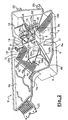
- the lower part 2 comprises substantially in the center of the lower part 4b a compartment 8 of parallelepipedal general shape, formed by four partitions vertical 9 made in one piece with the bottom wall 4.
- Ribs 10a, 10b and 10c vertical, made in one piece with the bottom wall 4, protrude on the lower part 4b.
- the rib 10a extends between the upright 4c and an edge of the compartment 8.
- the ribs 10b and 10c extend between a side 6a of the side wall 6 of the lower part 2 and a partition 9.
- the ribs 10a, 10b and 10c are traversed, at their connection in the compartment 8 and at their base, openings 11 which allow a circulation of fuel around compartment 8.
- the location of the compartment 8 corresponds substantially to the low point of the tank.
- This fuel pump 12 is fixed in the compartment 8 by means of a fastening member 13 which comprises a central portion 13a of tubular shape, which receives the fuel pump 12, and four radial fins 13b having ribs at their ends, these ribs being arranged to fit vertically in slides 14 made on the inside faces of the partitions 9.
- a fastening member 13 which comprises a central portion 13a of tubular shape, which receives the fuel pump 12, and four radial fins 13b having ribs at their ends, these ribs being arranged to fit vertically in slides 14 made on the inside faces of the partitions 9.
- the fixing member 13 is made of a material having good absorption properties of mechanical vibrations, which reduces the noise of pump operation by making it more difficult to transmit the vibrations of operation of the pump 12 at the bottom wall 4.
- the fuel pump 12 has a suction inlet which draws the fuel through a strainer in the bottom of the compartment 8.
- the fuel pump 12 is connected to the power supply of the vehicle at the by means of an electric cable 19 and an electrical connector 20 attached in a sealed manner in an opening of the side wall 6 of the tank.
- the output of the fuel pump 12 is connected by a pipe 15 to a filter with fuel fixed from the outside of the tank in a housing 16 made of a single holding by plastic molding with the side wall 6 of the lower part 2.
- the tank 1 also comprises a pressure regulator 21 fixed on the lower part 4b, near compartment 8.
- This pressure regulator 21 is connected to the fuel filter contained in the housing 16 by a pipe 22.
- the aforementioned fuel filter comprises a tip 23 that can be seen on the Figure 1, intended to be connected by a conduit (not shown) to the vehicle engine.
- Fuel that is not consumed by the engine and that has been sucked by the pump 12 and sent to the fuel filter is returned to the tank by the tubing 22 and exits through the pressure regulator 21, near the compartment 8, so that when only a small amount of fuel remains in the fuel tank, the fuel which is discharged by the pressure regulator 21 can be quickly re-aspirated by the pump 12.
- the tank 1 further comprises a fuel gauge 24 fixed on the rib 7b, this gauge being connected to the electrical connector 20 and having an articulated arm 24a provided at its end with a float 24b.
- One of the partitions 9 defining the compartment 8 has an extension vertical 9a whose upper edge is concave upwards, to serve as a support for the end of a filling pipe 40, as will be specified in the following in referring to Figure 3.
- the lower portion 2 has outer legs 25 for fixing tank 1 on the vehicle.
- FIG. 4 shows the upper part 3.
- the upper part 3 is shaped to receive the filler neck 40 above.
- This filling pipe 40 passes through the side wall of the part superior 3.
- a housing 31 is made in one piece by molding with the part superior 3 to receive a canister.
- the housing 31 is open towards the outside of the tank to allow the setting in place of the canister from the outside, and possibly its replacement.
- the housing 31 communicates with the interior of the tank by a tip 32 made in one piece with the upper part 3 during the molding of the latter.
- This endpiece 32 is connected by a pipe 33 to a valve 34 fixed by snap into a recess 39 located substantially at the high point of the tank.
- Tabs 35 having recesses 35a in which flapper teeth 34 can engage are arranged in the recess 39, as can be seen on Figure 5.
- the canister placed in the housing 31 communicates with the outside by two tips 37 and 38 that can be seen in Figure 1, one of which communicates with the air ambient and the other with a purge system to reactivate activated carbons contained in the canister.
- the lower end 42 of the filler neck 40 is positioned, when the lower 2 and upper 3 parts of the tank are assembled, so as to that the fuel falls in the compartment 8.
- This configuration makes it possible to fill the compartment 8, which is advantageous when only a small amount of fuel to fill the tank.
- compartment 8 With a fuel quantity lower than a few liters is enough to allow the priming of the fuel pump 12.
- the upper part 3 has a rib 36 whose lower edge is concave downwards, this rib 36 being arranged so as to position itself with a slight shift above the above-mentioned extension 9a, in order to maintain the tubing 40 against this extension 9a when the tank 1 is assembled.
- a degassing pipe 50 serving to trigger the gun of filling is fixed on the upper part 3, opening at one end 1 nearby the high point of the tank and connecting at the other end to a tip 52, as one can be seen in Figures 3 and 4.
- the tip 52 is made in one piece with the upper part 3, during the molding of the latter, and communicates with an outer end 54.
Landscapes
- Engineering & Computer Science (AREA)
- Life Sciences & Earth Sciences (AREA)
- Sustainable Development (AREA)
- Sustainable Energy (AREA)
- Chemical & Material Sciences (AREA)
- Combustion & Propulsion (AREA)
- Transportation (AREA)
- Mechanical Engineering (AREA)
- Cooling, Air Intake And Gas Exhaust, And Fuel Tank Arrangements In Propulsion Units (AREA)
- Moulding By Coating Moulds (AREA)
- Blow-Moulding Or Thermoforming Of Plastics Or The Like (AREA)
Description
- la pompe à carburant,
- un régulateur de pression,
- une jauge à carburant.
- un clapet,
- une tubulure de remplissage,
- un conduit de dégazage.
- la figure 1 est une vue en perspective, schématique, d'un réservoir conforme à un exemple de mise en oeuvre de l'invention,
- la figure 2 est une vue schématique de l'intérieur de la partie inférieure du réservoir de la figure 1,
- la figure 3 est une vue schématique de la moitié du réservoir de la figure 1, observée dans un plan de coupe vertical,
- la figure 4 est une vue schématique de dessous de la partie supérieure du réservoir de la figure 1, et
- la figure 5 représente de manière schématique un détail de la figure 4.
- fermer l'accès à la tubulure 33 en cas de retournement du véhicule,
- créer une perte de charge importante au-delà d'un niveau de carburant prédéterminé dans le réservoir pour empêcher le sur-remplissage,
- empêcher les projections de carburant liquide d'atteindre le canister.
Claims (22)
- Réservoir à carburant (1) comportant une enveloppe formée par l'assemblage d'au moins deux parties de réservoir (2, 3) réalisées par moulage de matière plastique et définissant, lorsque assemblées, la surface intérieure du réservoir (1), et comportant un compartiment (8) placé dans un point bas du réservoir (1) à l'intérieur duquel se trouve une pompe à carburant (12), fixée sur la surface intérieuredu réservoir avant l'assemblage des parties de réservoir, l'une des parties de réservoir comportant une tubulure de remplissage (40), ledit réservoir étant caractérisé par le fait :que l'extrémité (42) de la tubulure de remplissage (40) par laquelle sort le carburant est positionnée de manière à ce que le carburant tombe lors du remplissage dans le compartiment (8);que la pompe (12) est supportée par des moyens de support (13) permettant d'éviter la transmission des vibrations de la pompe au réservoir; etque les moyens de support comportent une partie centrale (13a) agencée pour recevoir la pompe et des ailettes (13b) permettant d'assurer le maintien de cette partie centrale, agencées pour se fixer à la paroi définissant ledit compartiment.
- Réservoir selon la revendication précédente, caractérisé par le fait que l'enveloppe du réservoir est dépourvue d'orifice traversant destiné à l'introduction à l'intérieur du réservoir d'un élément rapporté.
- Réservoir selon la revendication 1, la pompe comportant un corps, caractérisé par le fait que l'enveloppe du réservoir est dépourvue d'orifice traversant de section supérieure aux dimensions du corps de la pompe à carburant.
- Réservoir selon la revendication 1, caractérisé par le fait que l'enveloppe du réservoir est dépourvue d'orifice traversant situé au droit de la pompe à carburant.
- Réservoir selon l'une quelconque des revendications précédentes, caractérisé par le fait qu'il comporte au moins un élément rapporté tel qu'une jauge, fixé sur la surface intérieure du réservoir et séparé de ladite pompe à carburant.
- Réservoir selon l'une quelconque des revendications précédentes caractérisé par le fait que le compartiment (8) est réalisé d'un seul tenant par moulage de matière avec ladite partie de réservoir.
- Réservoir selon l'une quelconque des revendications précédentes,
caractérisé par le fait que les deux.parties de réservoir (2, 3) sont réalisées par moulage par injection de matière thermoplastique. - Réservoir selon l'une des deux revendications précédentes, caractérisé par le fait qu'au moins l'une des parties de réservoir (2, 3) comporte des moyens de fixation (7b ; 9 ; 9a ; 35) destinés à permettre le montage d'un élément rapporté (13 ; 24 ; 34) à l'intérieur du réservoir, ces moyens de fixation étant réalisés d'un seul tenant par moulage de matière avec ladite partie de réservoir.
- Réservoir selon la revendication immédiatement précédente, caractérisé par le fait que les moyens de fixation comportent au moins une paroi (9 ; 35) formant saillie à l'intérieur du réservoir (1).
- Réservoir selon la revendication immédiatement précédente, caractérisé par le fait que la paroi (35) comporte au moins un évidement (35a) permettant de recevoir un organe de fixation de l'élément rapporté (34).
- Réservoir selon la revendication 9, caractérisé par le fait que ladite paroi comporte au moins une dent destinée à s'encliqueter dans un évidement de l'élément rapporté.
- Réservoir selon l'une quelconque des revendications précédentes, caractérisé par le fait qu'au moins l'une des parties de réservoir comporte un logement (31) permettant la fixation sur le réservoir d'un élément par extérieur du réservoir, ce logement étant défini par une paroi venue de moulage avec la partie de réservoir concerné.
- Réservoir selon la revendications immédiatement précédente, caractérisé par le fait que ledit élément est un filtre à carburant.
- Réservoir selon la revendication 12, caractérisé par le fait que ledit élément est un canister.
- Réservoir selon l'une quelconque des revendications précédentes, caractérisé par le fait que l'une des parties de réservoir (2, 3) forme sensiblement la moitié inférieure et l'autre partie forme sensiblement la moitié supérieure.
- Réservoir selon l'une quelconque des revendications précédentes, caractérisé par le fait que la partie inférieure (2) du réservoir comporte un logement (16) défini par une paroi réalisée d'un seul tenant par moulage de matière avec cette partie, pour recevoir un filtre à carburant.
- Réservoir selon l'une quelconque des revendications précédentes,
caractérisé par le fait que la partie supérieure (3) du réservoir comporte un logement (31) défini par une paroi réalisée d'un seul tenant par moulage de matière avec cette partie, pour recevoir un canister. - Réservoir selon l'une quelconque des revendications précédentes, caractérisé par le fait que la surface intérieure du réservoir comporte des nervures (10a, 10b, 10c) sensiblement verticales.
- Réservoir selon la revendication immédiatement précédente, caractérisé par le fait qu'au moins une nervure (10a, 10b, 10c) est traversée à sa base par un passage (11) permettant la circulation du carburant.
- Réservoir selon la revendication immédiatement précédente, caractérisé par le fait qu'il comporte une jauge à carburant (24) fixée sur la surface intérieure du réservoir (1).
- Réservoir selon l'une quelconque des revendications précédentes, caractérisé par le fait qu'il comporte un régulateur de pression (21) fixé sur la surface intérieure du réservoir (1) à proximité de son point bas.
- Réservoir selon l'une quelconque des revendications précédentes, caractérisé par le fait que les parties de réservoir (2, 3) sont assemblées par collage ou soudage.
Applications Claiming Priority (2)
| Application Number | Priority Date | Filing Date | Title |
|---|---|---|---|
| FR0005638A FR2808471B1 (fr) | 2000-05-03 | 2000-05-03 | Reservoir a carburant et procede de fabrication |
| FR0005638 | 2000-05-03 |
Publications (2)
| Publication Number | Publication Date |
|---|---|
| EP1151887A1 EP1151887A1 (fr) | 2001-11-07 |
| EP1151887B1 true EP1151887B1 (fr) | 2005-11-30 |
Family
ID=8849837
Family Applications (1)
| Application Number | Title | Priority Date | Filing Date |
|---|---|---|---|
| EP01401115A Expired - Lifetime EP1151887B1 (fr) | 2000-05-03 | 2001-04-27 | Réservoir à carburant et procédé de fabrication |
Country Status (6)
| Country | Link |
|---|---|
| US (1) | US6948511B2 (fr) |
| EP (1) | EP1151887B1 (fr) |
| AT (1) | ATE311302T1 (fr) |
| BR (1) | BR0101668A (fr) |
| DE (1) | DE60115319T2 (fr) |
| FR (1) | FR2808471B1 (fr) |
Families Citing this family (16)
| Publication number | Priority date | Publication date | Assignee | Title |
|---|---|---|---|---|
| FR2806959B1 (fr) * | 2000-04-03 | 2003-02-14 | Plastic Omnium Cie | Procede de fabrication d'un reservoir en matiere thermoplastique soufflee incorporant un insert |
| FR2833890B1 (fr) | 2001-12-21 | 2005-04-22 | Inergy Automotive Systems Man | Reservoir a carburant pour vehicule automobile |
| US20030136507A1 (en) * | 2002-01-18 | 2003-07-24 | Thiel Steven A. | Thermoformed fuel tank fuel delivery system and assembly method |
| DE102006027255A1 (de) * | 2006-06-09 | 2007-12-13 | Kautex Textron Gmbh & Co. Kg | Verfahren zur Herstellung von Hohlkörpern aus thermoplastischem Kunststoff |
| US20080014390A1 (en) * | 2006-06-30 | 2008-01-17 | Scott Craig S | Multi-layer Thermoformed Fuel Tank and Method of Manufacturing the Same |
| JP4575335B2 (ja) * | 2006-06-30 | 2010-11-04 | 本田技研工業株式会社 | 燃料タンク |
| CN101687463A (zh) * | 2007-06-22 | 2010-03-31 | 考特克斯·特克斯罗恩有限公司及两合公司 | 燃料容器 |
| ATE507056T1 (de) | 2007-10-02 | 2011-05-15 | Inergy Automotive Systems Res | Verfahren zur herstellung eines kraftstofftanks aus kunststoff |
| US8590565B2 (en) * | 2007-11-27 | 2013-11-26 | Honda Motor Co., Ltd. | Fuel tank |
| WO2012075355A1 (fr) | 2010-12-03 | 2012-06-07 | Salflex Polymers Limited | Déflecteur de réservoir de carburant déployable et système de réservoir de carburant |
| DE102015209411A1 (de) * | 2015-05-22 | 2016-11-24 | Ford Global Technologies, Llc | Förderbaugruppe zum Fördern von Kraftstoff |
| DE102015217763B4 (de) * | 2015-09-16 | 2021-02-25 | Röchling Automotive SE & Co. KG | Tank für Lagerung und Lieferung von Flüssigkeiten mit an der Tankwandung angeordneten Funktionskomponenten |
| JP6704885B2 (ja) * | 2017-09-28 | 2020-06-03 | 本田技研工業株式会社 | 樹脂製燃料タンク |
| DE102018120441B4 (de) | 2017-09-28 | 2021-12-16 | Honda Motor Co., Ltd. | Aus Harz hergestellter Kraftstoffbehälter |
| DE102018201116B3 (de) * | 2018-01-24 | 2019-03-28 | Ford Global Technologies, Llc | Baugruppe für ein Hybridelektrofahrzeug und Hybridelektrofahrzeug |
| CN118103239A (zh) * | 2021-10-15 | 2024-05-28 | 海拉有限双合股份公司 | 冷却剂箱、冷却剂引导系统和机动车 |
Family Cites Families (18)
| Publication number | Priority date | Publication date | Assignee | Title |
|---|---|---|---|---|
| DE2723771C3 (de) * | 1977-05-26 | 1981-12-03 | Volkswagenwerk Ag, 3180 Wolfsburg | Behälteranordnung, insbesondere Kraftstoff-Behälteranordnung für ein Kraftfahrzeug |
| FR2460196A2 (fr) * | 1979-07-04 | 1981-01-23 | Transformat Mat Plastiques | Procede d'obtention de corps monobloc par soufflage et pourvu d'une partie saillante sur l'une de ses parois interieures |
| JPS61220929A (ja) * | 1985-03-27 | 1986-10-01 | Nissan Shatai Co Ltd | 自動車用燃料タンク装置 |
| JP2933692B2 (ja) * | 1990-08-03 | 1999-08-16 | 株式会社ニフコ | 車両用燃料タンクの旋回槽装置 |
| US5129544A (en) * | 1990-11-08 | 1992-07-14 | Jacobson Wendell L | Laminated fuel tank structure |
| US5850933A (en) * | 1991-09-17 | 1998-12-22 | Pazik; John A. | Molded gas tank with internal baffle |
| IT1257208B (it) | 1992-05-29 | 1996-01-10 | Fiat Auto Spa | Serbatoio di combustibile per autoveicoli e procedimento per la sua realizzazione. |
| US5394902A (en) * | 1994-04-29 | 1995-03-07 | Nifco, Inc. | Fuel pump inlet chamber assembly for a vehicle fuel tank |
| JP3758274B2 (ja) * | 1996-03-21 | 2006-03-22 | 株式会社デンソー | 燃料フィルタ |
| DE19613893A1 (de) * | 1996-04-06 | 1997-10-09 | Bayerische Motoren Werke Ag | Kraftstoffbehälter für Fahrzeuge |
| EP0864458B1 (fr) * | 1997-03-10 | 2002-04-03 | Robert Bosch Gmbh | Dispositif d'alimentation de carburant pour un monteur à combustion |
| US5931353A (en) * | 1997-04-28 | 1999-08-03 | Solvay (Societe Anonyme) | Plastic hollow body with internal fastening arrangement |
| US5951050A (en) * | 1997-09-18 | 1999-09-14 | Siekmann; Jim | Integral reservoir for tank |
| JP3591266B2 (ja) * | 1998-01-13 | 2004-11-17 | トヨタ自動車株式会社 | フューエルタンク |
| FR2774948B1 (fr) * | 1998-02-19 | 2000-05-05 | Plastic Omnium Cie | Reservoir a carburant a piege a carburant integre |
| FR2774950B1 (fr) * | 1998-02-19 | 2000-05-19 | Plastic Omnium Cie | Canister de reservoir a carburant et reservoir a carburant muni d'un tel canister |
| DE19853097C2 (de) * | 1998-11-18 | 2001-02-01 | Mannesmann Vdo Ag | Kraftstoffbehälter |
| JP3698293B2 (ja) * | 1999-02-18 | 2005-09-21 | 株式会社デンソー | 回転装置支持構造及びそれを用いる燃料供給装置 |
-
2000
- 2000-05-03 FR FR0005638A patent/FR2808471B1/fr not_active Expired - Fee Related
-
2001
- 2001-04-27 AT AT01401115T patent/ATE311302T1/de not_active IP Right Cessation
- 2001-04-27 DE DE60115319T patent/DE60115319T2/de not_active Expired - Lifetime
- 2001-04-27 EP EP01401115A patent/EP1151887B1/fr not_active Expired - Lifetime
- 2001-04-30 US US09/843,809 patent/US6948511B2/en not_active Expired - Lifetime
- 2001-05-03 BR BR0101668-7A patent/BR0101668A/pt not_active IP Right Cessation
Also Published As
| Publication number | Publication date |
|---|---|
| EP1151887A1 (fr) | 2001-11-07 |
| US6948511B2 (en) | 2005-09-27 |
| DE60115319D1 (de) | 2006-01-05 |
| DE60115319T2 (de) | 2006-08-17 |
| US20020011271A1 (en) | 2002-01-31 |
| FR2808471A1 (fr) | 2001-11-09 |
| FR2808471B1 (fr) | 2003-02-14 |
| BR0101668A (pt) | 2001-12-26 |
| ATE311302T1 (de) | 2005-12-15 |
Similar Documents
| Publication | Publication Date | Title |
|---|---|---|
| EP1151887A1 (fr) | Réservoir à carburant et procédé de fabrication | |
| EP1147934B1 (fr) | Réservoir à carburant de véhicule automobile | |
| FR2802978A1 (fr) | Module de transfert de carburant pour vehicule automobile | |
| EP1337413B1 (fr) | Reservoir a carburant de vehicule automobile | |
| FR2713715A1 (fr) | Module de circulation de carburant pour réservoir de carburant d'un véhicule. | |
| EP1375901B1 (fr) | Procédé d'assemblage d'une pompe électrique, et amortisseur de vibrations pour une telle pompe | |
| WO2002025094A1 (fr) | Dispositif de puisage et de jaugeage pour reservoir de carburant de vehicule automobile | |
| FR2778948A1 (fr) | Ensemble de pompage de carburant et reservoir de vehicule automobile equipe d'un tel ensemble de pompage | |
| EP2511417B2 (fr) | Appareil électroménager de repassage comportant un boîtier comprenant un réservoir et une pompe alimentée en liquide par le réservoir | |
| EP0798458B1 (fr) | Dispositif de pompage immergé dans un réservoir pour véhicule automobile | |
| EP1135589A1 (fr) | Ensemble de puisage de liquide, notamment pour additif de carburant | |
| CN1181458A (zh) | 空气滤清器 | |
| WO2004002798A1 (fr) | Reservoir de liquide hydraulique. | |
| EP1285805A1 (fr) | Ensemble multifonction d'un système à carburant, réservoir comprenant ledit ensemble et procédé de fabrication dudit système | |
| EP0666415B1 (fr) | Régulateur de pression interne à l'embase d'un ensemble de puisage | |
| FR2875859A1 (fr) | Dispositif porte-accessoires pour module de puisage du reservoir d'un vehicule automobile | |
| FR2567256A1 (fr) | Boite a eau pour echangeur de chaleur a encombrement frontal reduit, et echangeur de chaleur muni de cette boite a eau | |
| FR2915531A1 (fr) | Element filtrant pour un filtre a air d'un moteur a combustion interne | |
| FR2669864A1 (fr) | Clapet de ventilation pour un reservoir de carburant d'un vehicule. | |
| FR2864717A1 (fr) | Boitier de dispositif electrique comportant des moyens de fixation d'un organe de connexion electrique, un tel organe de connexion electrique, motoreducteur pour equipement de vehicule automobile comprenant un tel boitier | |
| EP0147330A1 (fr) | Pompe à membrane pour l'alimentation en essence d'un moteur de véhicule automobile. | |
| FR2713996A1 (fr) | Dispositif de puisage multiple pour réservoirs à plusieurs compartiments, notamment pour réservoirs de carburant de véhicules automobiles. | |
| EP2279921B1 (fr) | Réservoir de liquide de frein | |
| FR2712547A1 (fr) | Dispositif de remplissage de réservoir de liquide intégré à un projecteur de véhicule automobile. | |
| FR2722147A1 (fr) | Installation pour transferer du carburant d'un reservoir vers un moteur a combustion interne d'un vehicule automobile, comprenant une unite de transfert montee dans le reservoir |
Legal Events
| Date | Code | Title | Description |
|---|---|---|---|
| PUAI | Public reference made under article 153(3) epc to a published international application that has entered the european phase |
Free format text: ORIGINAL CODE: 0009012 |
|
| AK | Designated contracting states |
Kind code of ref document: A1 Designated state(s): AT BE CH CY DE DK ES FI FR GB GR IE IT LI LU MC NL PT SE TR |
|
| AX | Request for extension of the european patent |
Free format text: AL;LT;LV;MK;RO;SI |
|
| 17P | Request for examination filed |
Effective date: 20020330 |
|
| AKX | Designation fees paid |
Free format text: AT BE CH CY DE DK ES FI FR GB GR IE IT LI LU MC NL PT SE TR |
|
| 17Q | First examination report despatched |
Effective date: 20041012 |
|
| RAP1 | Party data changed (applicant data changed or rights of an application transferred) |
Owner name: INERGY AUTOMOTIVE SYSTEMS RESEARCH (SOCIETE ANONYM |
|
| GRAP | Despatch of communication of intention to grant a patent |
Free format text: ORIGINAL CODE: EPIDOSNIGR1 |
|
| GRAS | Grant fee paid |
Free format text: ORIGINAL CODE: EPIDOSNIGR3 |
|
| GRAA | (expected) grant |
Free format text: ORIGINAL CODE: 0009210 |
|
| AK | Designated contracting states |
Kind code of ref document: B1 Designated state(s): AT BE CH CY DE DK ES FI FR GB GR IE IT LI LU MC NL PT SE TR |
|
| PG25 | Lapsed in a contracting state [announced via postgrant information from national office to epo] |
Ref country code: IT Free format text: LAPSE BECAUSE OF FAILURE TO SUBMIT A TRANSLATION OF THE DESCRIPTION OR TO PAY THE FEE WITHIN THE PRESCRIBED TIME-LIMIT;WARNING: LAPSES OF ITALIAN PATENTS WITH EFFECTIVE DATE BEFORE 2007 MAY HAVE OCCURRED AT ANY TIME BEFORE 2007. THE CORRECT EFFECTIVE DATE MAY BE DIFFERENT FROM THE ONE RECORDED. Effective date: 20051130 Ref country code: NL Free format text: LAPSE BECAUSE OF FAILURE TO SUBMIT A TRANSLATION OF THE DESCRIPTION OR TO PAY THE FEE WITHIN THE PRESCRIBED TIME-LIMIT Effective date: 20051130 Ref country code: IE Free format text: LAPSE BECAUSE OF FAILURE TO SUBMIT A TRANSLATION OF THE DESCRIPTION OR TO PAY THE FEE WITHIN THE PRESCRIBED TIME-LIMIT Effective date: 20051130 Ref country code: GB Free format text: LAPSE BECAUSE OF FAILURE TO SUBMIT A TRANSLATION OF THE DESCRIPTION OR TO PAY THE FEE WITHIN THE PRESCRIBED TIME-LIMIT Effective date: 20051130 Ref country code: FI Free format text: LAPSE BECAUSE OF FAILURE TO SUBMIT A TRANSLATION OF THE DESCRIPTION OR TO PAY THE FEE WITHIN THE PRESCRIBED TIME-LIMIT Effective date: 20051130 Ref country code: AT Free format text: LAPSE BECAUSE OF FAILURE TO SUBMIT A TRANSLATION OF THE DESCRIPTION OR TO PAY THE FEE WITHIN THE PRESCRIBED TIME-LIMIT Effective date: 20051130 |
|
| REG | Reference to a national code |
Ref country code: CH Ref legal event code: EP Ref country code: GB Ref legal event code: FG4D Free format text: NOT ENGLISH |
|
| REG | Reference to a national code |
Ref country code: IE Ref legal event code: FG4D Free format text: LANGUAGE OF EP DOCUMENT: FRENCH |
|
| REF | Corresponds to: |
Ref document number: 60115319 Country of ref document: DE Date of ref document: 20060105 Kind code of ref document: P |
|
| PG25 | Lapsed in a contracting state [announced via postgrant information from national office to epo] |
Ref country code: SE Free format text: LAPSE BECAUSE OF FAILURE TO SUBMIT A TRANSLATION OF THE DESCRIPTION OR TO PAY THE FEE WITHIN THE PRESCRIBED TIME-LIMIT Effective date: 20060228 Ref country code: GR Free format text: LAPSE BECAUSE OF FAILURE TO SUBMIT A TRANSLATION OF THE DESCRIPTION OR TO PAY THE FEE WITHIN THE PRESCRIBED TIME-LIMIT Effective date: 20060228 Ref country code: DK Free format text: LAPSE BECAUSE OF FAILURE TO SUBMIT A TRANSLATION OF THE DESCRIPTION OR TO PAY THE FEE WITHIN THE PRESCRIBED TIME-LIMIT Effective date: 20060228 |
|
| PG25 | Lapsed in a contracting state [announced via postgrant information from national office to epo] |
Ref country code: ES Free format text: LAPSE BECAUSE OF FAILURE TO SUBMIT A TRANSLATION OF THE DESCRIPTION OR TO PAY THE FEE WITHIN THE PRESCRIBED TIME-LIMIT Effective date: 20060313 |
|
| PG25 | Lapsed in a contracting state [announced via postgrant information from national office to epo] |
Ref country code: LI Free format text: LAPSE BECAUSE OF NON-PAYMENT OF DUE FEES Effective date: 20060430 Ref country code: CH Free format text: LAPSE BECAUSE OF NON-PAYMENT OF DUE FEES Effective date: 20060430 Ref country code: MC Free format text: LAPSE BECAUSE OF NON-PAYMENT OF DUE FEES Effective date: 20060430 Ref country code: BE Free format text: LAPSE BECAUSE OF NON-PAYMENT OF DUE FEES Effective date: 20060430 |
|
| PG25 | Lapsed in a contracting state [announced via postgrant information from national office to epo] |
Ref country code: PT Free format text: LAPSE BECAUSE OF FAILURE TO SUBMIT A TRANSLATION OF THE DESCRIPTION OR TO PAY THE FEE WITHIN THE PRESCRIBED TIME-LIMIT Effective date: 20060502 |
|
| NLV1 | Nl: lapsed or annulled due to failure to fulfill the requirements of art. 29p and 29m of the patents act | ||
| GBV | Gb: ep patent (uk) treated as always having been void in accordance with gb section 77(7)/1977 [no translation filed] |
Effective date: 20051130 |
|
| REG | Reference to a national code |
Ref country code: IE Ref legal event code: FD4D |
|
| PLBE | No opposition filed within time limit |
Free format text: ORIGINAL CODE: 0009261 |
|
| STAA | Information on the status of an ep patent application or granted ep patent |
Free format text: STATUS: NO OPPOSITION FILED WITHIN TIME LIMIT |
|
| 26N | No opposition filed |
Effective date: 20060831 |
|
| REG | Reference to a national code |
Ref country code: CH Ref legal event code: PL |
|
| BERE | Be: lapsed |
Owner name: INERGY AUTOMOTIVE SYSTEMS RESEARCH (SOCIETE ANONY Effective date: 20060430 |
|
| PG25 | Lapsed in a contracting state [announced via postgrant information from national office to epo] |
Ref country code: TR Free format text: LAPSE BECAUSE OF FAILURE TO SUBMIT A TRANSLATION OF THE DESCRIPTION OR TO PAY THE FEE WITHIN THE PRESCRIBED TIME-LIMIT Effective date: 20051130 Ref country code: LU Free format text: LAPSE BECAUSE OF NON-PAYMENT OF DUE FEES Effective date: 20060427 |
|
| PG25 | Lapsed in a contracting state [announced via postgrant information from national office to epo] |
Ref country code: CY Free format text: LAPSE BECAUSE OF FAILURE TO SUBMIT A TRANSLATION OF THE DESCRIPTION OR TO PAY THE FEE WITHIN THE PRESCRIBED TIME-LIMIT Effective date: 20051130 |
|
| PGFP | Annual fee paid to national office [announced via postgrant information from national office to epo] |
Ref country code: FR Payment date: 20090417 Year of fee payment: 9 |
|
| REG | Reference to a national code |
Ref country code: FR Ref legal event code: ST Effective date: 20101230 |
|
| PG25 | Lapsed in a contracting state [announced via postgrant information from national office to epo] |
Ref country code: FR Free format text: LAPSE BECAUSE OF NON-PAYMENT OF DUE FEES Effective date: 20100430 |
|
| PGFP | Annual fee paid to national office [announced via postgrant information from national office to epo] |
Ref country code: DE Payment date: 20180420 Year of fee payment: 18 |
|
| REG | Reference to a national code |
Ref country code: DE Ref legal event code: R119 Ref document number: 60115319 Country of ref document: DE |
|
| PG25 | Lapsed in a contracting state [announced via postgrant information from national office to epo] |
Ref country code: DE Free format text: LAPSE BECAUSE OF NON-PAYMENT OF DUE FEES Effective date: 20191101 |