EP1150772B1 - Uniformly expandable multi-channel pipettor - Google Patents
Uniformly expandable multi-channel pipettor Download PDFInfo
- Publication number
- EP1150772B1 EP1150772B1 EP99962905A EP99962905A EP1150772B1 EP 1150772 B1 EP1150772 B1 EP 1150772B1 EP 99962905 A EP99962905 A EP 99962905A EP 99962905 A EP99962905 A EP 99962905A EP 1150772 B1 EP1150772 B1 EP 1150772B1
- Authority
- EP
- European Patent Office
- Prior art keywords
- pipetting system
- tip
- button
- fittings
- spacing
- Prior art date
- Legal status (The legal status is an assumption and is not a legal conclusion. Google has not performed a legal analysis and makes no representation as to the accuracy of the status listed.)
- Expired - Lifetime
Links
- 230000008602 contraction Effects 0.000 claims description 3
- 230000000994 depressogenic effect Effects 0.000 claims 3
- 230000008878 coupling Effects 0.000 claims 1
- 238000010168 coupling process Methods 0.000 claims 1
- 238000005859 coupling reaction Methods 0.000 claims 1
- 239000007788 liquid Substances 0.000 description 5
- 230000007423 decrease Effects 0.000 description 2
- 210000002445 nipple Anatomy 0.000 description 2
- 230000001154 acute effect Effects 0.000 description 1
- 239000012530 fluid Substances 0.000 description 1
- 238000007373 indentation Methods 0.000 description 1
- 238000012423 maintenance Methods 0.000 description 1
- 238000004519 manufacturing process Methods 0.000 description 1
- 230000013011 mating Effects 0.000 description 1
- 238000012986 modification Methods 0.000 description 1
- 230000004048 modification Effects 0.000 description 1
- 239000013610 patient sample Substances 0.000 description 1
- 230000000007 visual effect Effects 0.000 description 1
Images


Classifications
-
- B—PERFORMING OPERATIONS; TRANSPORTING
- B01—PHYSICAL OR CHEMICAL PROCESSES OR APPARATUS IN GENERAL
- B01L—CHEMICAL OR PHYSICAL LABORATORY APPARATUS FOR GENERAL USE
- B01L3/00—Containers or dishes for laboratory use, e.g. laboratory glassware; Droppers
- B01L3/02—Burettes; Pipettes
- B01L3/0275—Interchangeable or disposable dispensing tips
-
- B—PERFORMING OPERATIONS; TRANSPORTING
- B01—PHYSICAL OR CHEMICAL PROCESSES OR APPARATUS IN GENERAL
- B01L—CHEMICAL OR PHYSICAL LABORATORY APPARATUS FOR GENERAL USE
- B01L3/00—Containers or dishes for laboratory use, e.g. laboratory glassware; Droppers
- B01L3/02—Burettes; Pipettes
- B01L3/021—Pipettes, i.e. with only one conduit for withdrawing and redistributing liquids
- B01L3/0217—Pipettes, i.e. with only one conduit for withdrawing and redistributing liquids of the plunger pump type
-
- G—PHYSICS
- G01—MEASURING; TESTING
- G01N—INVESTIGATING OR ANALYSING MATERIALS BY DETERMINING THEIR CHEMICAL OR PHYSICAL PROPERTIES
- G01N35/00—Automatic analysis not limited to methods or materials provided for in any single one of groups G01N1/00 - G01N33/00; Handling materials therefor
- G01N35/10—Devices for transferring samples or any liquids to, in, or from, the analysis apparatus, e.g. suction devices, injection devices
- G01N35/1065—Multiple transfer devices
- G01N35/1067—Multiple transfer devices for transfer to or from containers having different spacing
- G01N2035/1069—Multiple transfer devices for transfer to or from containers having different spacing by adjusting the spacing between multiple probes of a single transferring head
Definitions
- This invention relates generally to liquid transfer devices used in laboratories and, more particularly, to a multi-channel pipetting device which enables the user to uniformly, rapidly and accurately adjust the spacings between pipette tips.
- Pipetting systems are used in laboratories for the transfer of relatively small quantities of liquids.
- the liquid is normally drawn into the tips by suction and is subsequently released into the wells of microtiter plates or other receptacles.
- the transfer involves patient samples which are moved from one set of spaced receptacles to another set of receptacles having a different spacing.
- a multi-channel pipettor capable of being simply manipulated to vary the spacing between the pipette tips is often used for this purpose.
- the pipettor has a tip removing assembly that, with a minimum of force, removes tips safely and efficiently regardless of the positions of the tips and their fittings on the pipettor.
- a second type of multi-channel pipettor such as that shown in U.S. Patent No. 5,057,281 , allows the spacings between the tip fittings to be varied by the user.
- the spacings between each fitting must be individually set.
- considerable manipulation is required to move the tip fittings from one set of spacings to another and it is difficult to accurately set the tip fittings to the desired spacings.
- the document NL-A-6504453 describes a multi-channel pipetting system having a pantographic linkage which allows the maintenance of identical spacings between adjacent tip fittings, and an adjustable stop which consists of an element movable along a rod which is not connected to the pantographic linkage.
- the pipetting system of the present invention which uniformly and accurately spaces the tip fittings within a range of spacings, while still providing for easy tip removal. Moreover, the tip fittings may be rapidly moved from one set of uniform spacings to another. In addition, a desired spacing may be readily adjustably set.
- the embodiment of the invention is a multi-channel pipetting system according to claim 1.
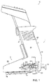
- the pipettor 10 of this invention has a boot-shaped housing 1 as shown in FIG. 1 that includes a handle section 2 and a lower section 3, having a bottom section 8, from which a plurality of tip fittings 7 project downwardly.
- a boot-shaped housing 1 as shown in FIG. 1 that includes a handle section 2 and a lower section 3, having a bottom section 8, from which a plurality of tip fittings 7 project downwardly.
- eight tip fittings are included, but it should be appreciated that the number may vary, depending upon a user's needs.
- the housing 1 of the pipetting system typically is formed of a pair of mating half shells 1a (not illustrated) and 1b.
- the shells 1a and 1b include sidewalls 19 and 20 (not illustrated) and front and back walls 21 and 22 that together define the handle section 2 and the lower section 3.
- the front, back and bottom of the lower section 3 are enclosed by the walls 21, 22 and 23, while the top of the bottom section forward of the handle is enclosed by wall 24.
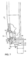
- FIGS. 6 and 7 show a tip fitting mounting plate 80, which is secured immediately above the bottom wall 23 of the housing by slots 81 formed in each half shell 1a and 1b.
- the tip fitting mounting plate 80 includes an elongated slotted track 82.
- the elongated slotted track 82 is narrower and somewhat shorter than the aperture 25 in the bottom wall 23.
- each of the tip fittings disposed in the elongated slotted track 82 includes a stem 94.
- the width of stem 94 at its upper end is larger than the width of the elongated slotted track 82. Consequently, the edges of the stem 94 bear against the lower surface of the mounting plate 80.
- each tip fitting has a waist 96 which rides along the elongated slotted track 82.
- Each tip fitting has a shoulder 95 above the waist 96.
- the shoulder 95 has a width greater than the elongated slotted track 82, which forms a track along which all the tip fittings 7 are slidably disposed, and which guides tip fittings 7.
- Tip fitting 7a is fixed with respect to the track and does not move. Therefore, with the exception of tip fitting 7a, the tip fittings may be moved toward and away from the front wall 21.
- pipette tips 6 are attachable to the tip fittings 7.
- the upper end of each tip fitting carries a nipple 98 which in turn is connected to a duct 115, only an exemplary one of which is shown.
- a passage extends through each tip fitting from the lower end of the stem 94 to the upper end of nipple 98, which passage is in fluid communication with each duct 115.
- the pipetting system 10 includes a means for drawing liquid in metered volumes into the tips 6 and for expelling the liquid from the tips. This feature is not part of the present invention, and is well known to one of ordinary skill. This feature is described in U.S. patent No. 5,061,449 , assigned to the assignee of the present application.
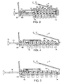
- the tip fittings 7 are connected together by a linkage that maintains a substantially identical, uniform spacing between each of the tip fittings, regardless of the position of the tip fittings.
- a pantographic linkage 89 is used.
- the pantographic linkage of the preferred embodiment includes intersecting first links 83 and second links 84.
- a first, lower end of each first link 83 is pivotably mounted to an associated tip fitting 7,
- An upper, second end of each second link 84 is pivotably mounted to an upper second end of an immediately adjacent first link 83.
- a second, lower end of each second link is pivotably mounted to an immediately adjacent tip fitting 7.
- Associated first links 83 and second links 84 are pivotably coupled at their respective centers,
- FIG. 3 shows the tip fittings with the minimum spacing
- FIG. 4 shows an intermediate spacing
- FIG. 5 shows the linkage 89 fully extended so that the tip fittings 7 are at their maximum spacing.
- side wall 19 has an elongated opening 71
- upper and lower rails 72 and 73 are disposed parallel to and on either side of opening 71.
- the rails 72 and 73 extend along the direction of travel of the tip fittings.
- the rails include respective opposed surfaces 72a and 73a that form an acute angle with respect to plate 80 and that are angled with respect to one another such that the surfaces 72a and 73a of respective rails 72 and 73 are closer together facing side wall 19 than facing inwardly away from side wall 19 and toward side wall 20.
- the surfaces 72a and 73a of respective rails 72 and 73 are friction surfaces and contain serrations or ridges or are otherwise roughened as shown in FIGS. 6 and 7.
- a finger actuated stop 75 such as a button having a finger engageable surface 78 is also slidably engaged with the rails.
- the stop 75 has serrated, ridged or roughened friction surfaces 76 and 77 disposed parallel to respective surfaces 72a and 73a of respective rails 72 and 73, and which are urged into positive engagement with the rails 72 and 73 by biasing spring 79, as shown in FIG. 6.
- Spring 79 bears against rails 72 and 73 and pushes stop 75 outwardly. Applying finger pressure to the stop 75 toward wall 19 compresses the spring and releases the surfaces 76 and 77 from engagement with surfaces 72a and 73a of respective rails 72 and 73, The stop is then movable along rails 72 and 73 and within opening 71.
- a second finger actuated stop (not shown) may be included within the rails to limit the contraction of the pantographic linkage.
- a second finger actuated stop [(not shown)] 110 may be included within the rails to limit the contraction of the pantographic linkage.
- a spacing indicator 74 is slidably engaged with the rails 72 and 73 and is connected to the rear-most tip fitting 7b.
- indicator 74 could be affixed to another tip fitting 7, if desired.
- Indicator 74 moves with tip fitting 7b and provides an indication of the spacing between adjacent tip fittings, Indicator 74 extends through opening 71 to be externally visible.
- a visual scale 105 as shown in FIG. 1, is provided along opening 71 and is calibrated to provide the spacing between each tip fitting for a particular location of indicator 74 with respect to scale 105.
- the spacing between the tip fittings is that shown on scale 105 with which indicator 74 is aligned.
- the spacing between the tip fittings may alternatively or additionally be positively established by notches provided in the rod 11 corresponding with a ball detent as disclosed in U.S. Patent No. 5,061,449 .
- the tip fittings 7 are designed to slide in the tip fitting mounting plate 80 in response to movement of linkage 89.
- linkage 89 When linkage 89 is extended, the spacing between tip fittings 7 increases. Conversely, when linkage 89 is contracted, the spacing between tip fittings 7 decreases. Pulling the actuating rod 11 away from the housing 1 increases the spacing between tip fittings 7. Conversely, pushing the actuating rod 11 toward the housing 1 decreases the spacing between tip fittings 7.
- the finger actuated stop 75 may be adjustably set with reference to the scale 105 to provide a uniform spacing between tip fittings. Stop 75 is pushed inwardly with a finger and slidably moved within the opening 71 until stop 75 is aligned with a desired reading on scale 105. Stop 75 is then released and surfaces 76 and 77 engage respective surfaces 72a and 73a to hold stop 75 in place. The user then grasps knob 12 and moves rod 11 until indicator 74 abuts shoulder 75a on stop 75, or on stop 110. At that point, tip fittings 7 are uniformly spaced apart as indicated by the reading on the scale 105 aligned with indicator 74. The pipettor is now ready for use.
Landscapes
- Health & Medical Sciences (AREA)
- Chemical & Material Sciences (AREA)
- Clinical Laboratory Science (AREA)
- Chemical Kinetics & Catalysis (AREA)
- Analytical Chemistry (AREA)
- Life Sciences & Earth Sciences (AREA)
- Physics & Mathematics (AREA)
- Biochemistry (AREA)
- General Health & Medical Sciences (AREA)
- General Physics & Mathematics (AREA)
- Immunology (AREA)
- Pathology (AREA)
- Devices For Use In Laboratory Experiments (AREA)
- Sampling And Sample Adjustment (AREA)
Applications Claiming Priority (3)
| Application Number | Priority Date | Filing Date | Title |
|---|---|---|---|
| US211767 | 1998-12-15 | ||
| US09/211,767 US6235244B1 (en) | 1998-12-14 | 1998-12-15 | Uniformly expandable multi-channel pipettor |
| PCT/US1999/028158 WO2000035584A1 (en) | 1998-12-15 | 1999-11-29 | Uniformly expandable multi-channel pipettor |
Publications (3)
| Publication Number | Publication Date |
|---|---|
| EP1150772A1 EP1150772A1 (en) | 2001-11-07 |
| EP1150772A4 EP1150772A4 (en) | 2004-11-10 |
| EP1150772B1 true EP1150772B1 (en) | 2008-01-02 |
Family
ID=22788292
Family Applications (1)
| Application Number | Title | Priority Date | Filing Date |
|---|---|---|---|
| EP99962905A Expired - Lifetime EP1150772B1 (en) | 1998-12-15 | 1999-11-29 | Uniformly expandable multi-channel pipettor |
Country Status (4)
| Country | Link |
|---|---|
| EP (1) | EP1150772B1 (enExample) |
| JP (1) | JP4981209B2 (enExample) |
| DE (1) | DE69937903T2 (enExample) |
| WO (1) | WO2000035584A1 (enExample) |
Families Citing this family (7)
| Publication number | Priority date | Publication date | Assignee | Title |
|---|---|---|---|---|
| CH701163B1 (de) * | 2004-06-24 | 2010-12-15 | Tecan Trading Ag | System zum Manipulieren von Flüssigkeitsproben sowie Vorrichtung und Verfahren zum Anordnen von Pipetten- oder Dispenserspitzen in einem solchen System. |
| US7947234B2 (en) * | 2007-10-17 | 2011-05-24 | Rainin Instrument, Llc | Liquid end assembly for a handheld multichannel pipette with adjustable nozzle spacing |
| US8029742B2 (en) * | 2008-05-05 | 2011-10-04 | Integra Biosciences Corp. | Multi-channel pipettor with repositionable tips |
| WO2011157303A1 (en) * | 2010-06-18 | 2011-12-22 | Tecan Trading Ag | Spread sheare |
| CN207562916U (zh) * | 2017-04-17 | 2018-07-03 | 贝克曼库尔特有限公司 | 再水化器/接种器装置 |
| CN108408178A (zh) * | 2018-04-16 | 2018-08-17 | 苏州工业园区创晖隆自动化科技有限公司 | 变距贴标装置 |
| EP3932557B1 (de) * | 2020-07-02 | 2023-11-15 | Eppendorf SE | Mehrkanalpipettierkopf |
Family Cites Families (3)
| Publication number | Priority date | Publication date | Assignee | Title |
|---|---|---|---|---|
| JPS6450928A (en) * | 1987-08-21 | 1989-02-27 | Berun Kk | Handy distributing system |
| US5061449A (en) * | 1989-07-25 | 1991-10-29 | Matrix Technologies, Corp. | Expandable multi-channel pipetter |
| JPH09318636A (ja) * | 1996-05-30 | 1997-12-12 | Suzuki Motor Corp | 分注装置 |
-
1999
- 1999-11-29 JP JP2000587887A patent/JP4981209B2/ja not_active Expired - Lifetime
- 1999-11-29 EP EP99962905A patent/EP1150772B1/en not_active Expired - Lifetime
- 1999-11-29 WO PCT/US1999/028158 patent/WO2000035584A1/en not_active Ceased
- 1999-11-29 DE DE69937903T patent/DE69937903T2/de not_active Expired - Lifetime
Also Published As
| Publication number | Publication date |
|---|---|
| EP1150772A4 (en) | 2004-11-10 |
| DE69937903D1 (de) | 2008-02-14 |
| JP2002532227A (ja) | 2002-10-02 |
| DE69937903T2 (de) | 2009-01-02 |
| EP1150772A1 (en) | 2001-11-07 |
| WO2000035584A8 (en) | 2001-03-01 |
| WO2000035584A1 (en) | 2000-06-22 |
| JP4981209B2 (ja) | 2012-07-18 |
Similar Documents
| Publication | Publication Date | Title |
|---|---|---|
| US6235244B1 (en) | Uniformly expandable multi-channel pipettor | |
| EP0483225B1 (en) | Hand held multi-channel pipetter | |
| US5254083A (en) | Suction and irrigation apparatus | |
| US4009611A (en) | Hand-held micropipettor with improved pipette tip ejector | |
| US4151750A (en) | Device for detaching and removing a disposable tip of a pipette | |
| US6159164A (en) | Blood sampling system | |
| US2889848A (en) | Flow control clamp | |
| US3855867A (en) | Liquid transfer pipetting device | |
| US4799496A (en) | Guide wire handle | |
| US5406856A (en) | Pipetting apparatus | |
| US4283950A (en) | Device for detaching and removing a disposable tip of a pipette | |
| US5057281A (en) | Adjustable multi-channel pipetter | |
| US4824642A (en) | Multi-channel pipetter | |
| EP1150772B1 (en) | Uniformly expandable multi-channel pipettor | |
| JPS5879547A (ja) | ピペツト構造、使い捨て先端およびピストン組立て装置 | |
| EP0472023A1 (en) | Assembly for aspirating tissue, including adapter for syringe | |
| US6074611A (en) | Micro-pipettor apparatus | |
| US6997067B2 (en) | Liquid sample pipette with detachable ejector | |
| EP1085944B1 (en) | Suction device with means for removing a replaceable tip | |
| JPH05501222A (ja) | ピペット装置 | |
| US20030039587A1 (en) | Transfer device | |
| WO1995017848A1 (en) | Biopsy syringe with slide valve | |
| GB1566791A (en) | Pipette | |
| AU2001250456B2 (en) | Pipette with tip ejector | |
| JPS58142243A (ja) | ピペツタ |
Legal Events
| Date | Code | Title | Description |
|---|---|---|---|
| PUAI | Public reference made under article 153(3) epc to a published international application that has entered the european phase |
Free format text: ORIGINAL CODE: 0009012 |
|
| 17P | Request for examination filed |
Effective date: 20010705 |
|
| AK | Designated contracting states |
Kind code of ref document: A1 Designated state(s): AT BE CH CY DE DK ES FI FR GB GR IE IT LI LU MC NL PT SE |
|
| AX | Request for extension of the european patent |
Free format text: AL;LT;LV;MK;RO;SI |
|
| RBV | Designated contracting states (corrected) |
Designated state(s): DE FI FR GB |
|
| A4 | Supplementary search report drawn up and despatched |
Effective date: 20040927 |
|
| RIC1 | Information provided on ipc code assigned before grant |
Ipc: 7G 01N 35/10 B Ipc: 7B 01L 3/02 A |
|
| GRAP | Despatch of communication of intention to grant a patent |
Free format text: ORIGINAL CODE: EPIDOSNIGR1 |
|
| GRAS | Grant fee paid |
Free format text: ORIGINAL CODE: EPIDOSNIGR3 |
|
| GRAA | (expected) grant |
Free format text: ORIGINAL CODE: 0009210 |
|
| AK | Designated contracting states |
Kind code of ref document: B1 Designated state(s): DE FI FR GB |
|
| REG | Reference to a national code |
Ref country code: GB Ref legal event code: FG4D |
|
| REF | Corresponds to: |
Ref document number: 69937903 Country of ref document: DE Date of ref document: 20080214 Kind code of ref document: P |
|
| PG25 | Lapsed in a contracting state [announced via postgrant information from national office to epo] |
Ref country code: FI Free format text: LAPSE BECAUSE OF FAILURE TO SUBMIT A TRANSLATION OF THE DESCRIPTION OR TO PAY THE FEE WITHIN THE PRESCRIBED TIME-LIMIT Effective date: 20080102 |
|
| ET | Fr: translation filed | ||
| PLBE | No opposition filed within time limit |
Free format text: ORIGINAL CODE: 0009261 |
|
| STAA | Information on the status of an ep patent application or granted ep patent |
Free format text: STATUS: NO OPPOSITION FILED WITHIN TIME LIMIT |
|
| 26N | No opposition filed |
Effective date: 20081003 |
|
| PGFP | Annual fee paid to national office [announced via postgrant information from national office to epo] |
Ref country code: GB Payment date: 20141119 Year of fee payment: 16 Ref country code: FR Payment date: 20141119 Year of fee payment: 16 |
|
| GBPC | Gb: european patent ceased through non-payment of renewal fee |
Effective date: 20151129 |
|
| REG | Reference to a national code |
Ref country code: FR Ref legal event code: ST Effective date: 20160729 |
|
| PG25 | Lapsed in a contracting state [announced via postgrant information from national office to epo] |
Ref country code: GB Free format text: LAPSE BECAUSE OF NON-PAYMENT OF DUE FEES Effective date: 20151129 |
|
| PG25 | Lapsed in a contracting state [announced via postgrant information from national office to epo] |
Ref country code: FR Free format text: LAPSE BECAUSE OF NON-PAYMENT OF DUE FEES Effective date: 20151130 |
|
| PGFP | Annual fee paid to national office [announced via postgrant information from national office to epo] |
Ref country code: DE Payment date: 20181113 Year of fee payment: 20 |
|
| REG | Reference to a national code |
Ref country code: DE Ref legal event code: R071 Ref document number: 69937903 Country of ref document: DE |