EP1149994A2 - Kühlsystem für eine mit Flüssigkeit gekühlte Brennkraftmaschine - Google Patents
Kühlsystem für eine mit Flüssigkeit gekühlte Brennkraftmaschine Download PDFInfo
- Publication number
- EP1149994A2 EP1149994A2 EP01106208A EP01106208A EP1149994A2 EP 1149994 A2 EP1149994 A2 EP 1149994A2 EP 01106208 A EP01106208 A EP 01106208A EP 01106208 A EP01106208 A EP 01106208A EP 1149994 A2 EP1149994 A2 EP 1149994A2
- Authority
- EP
- European Patent Office
- Prior art keywords
- coolant
- cooling system
- housing
- thermostatic valve
- combustion engine
- Prior art date
- Legal status (The legal status is an assumption and is not a legal conclusion. Google has not performed a legal analysis and makes no representation as to the accuracy of the status listed.)
- Withdrawn
Links
- 238000001816 cooling Methods 0.000 title claims abstract description 30
- 238000002485 combustion reaction Methods 0.000 title claims abstract description 22
- 239000007788 liquid Substances 0.000 title 1
- 239000002826 coolant Substances 0.000 claims abstract description 93
- 238000007789 sealing Methods 0.000 description 6
- 238000012423 maintenance Methods 0.000 description 2
- 238000004519 manufacturing process Methods 0.000 description 2
- 230000005540 biological transmission Effects 0.000 description 1
- 230000008092 positive effect Effects 0.000 description 1
- 238000012805 post-processing Methods 0.000 description 1
- 230000007704 transition Effects 0.000 description 1
- 238000010792 warming Methods 0.000 description 1
- XLYOFNOQVPJJNP-UHFFFAOYSA-N water Substances O XLYOFNOQVPJJNP-UHFFFAOYSA-N 0.000 description 1
Images

Classifications
-
- F—MECHANICAL ENGINEERING; LIGHTING; HEATING; WEAPONS; BLASTING
- F01—MACHINES OR ENGINES IN GENERAL; ENGINE PLANTS IN GENERAL; STEAM ENGINES
- F01P—COOLING OF MACHINES OR ENGINES IN GENERAL; COOLING OF INTERNAL-COMBUSTION ENGINES
- F01P7/00—Controlling of coolant flow
- F01P7/14—Controlling of coolant flow the coolant being liquid
- F01P7/16—Controlling of coolant flow the coolant being liquid by thermostatic control
-
- F—MECHANICAL ENGINEERING; LIGHTING; HEATING; WEAPONS; BLASTING
- F01—MACHINES OR ENGINES IN GENERAL; ENGINE PLANTS IN GENERAL; STEAM ENGINES
- F01P—COOLING OF MACHINES OR ENGINES IN GENERAL; COOLING OF INTERNAL-COMBUSTION ENGINES
- F01P5/00—Pumping cooling-air or liquid coolants
- F01P5/10—Pumping liquid coolant; Arrangements of coolant pumps
-
- F—MECHANICAL ENGINEERING; LIGHTING; HEATING; WEAPONS; BLASTING
- F02—COMBUSTION ENGINES; HOT-GAS OR COMBUSTION-PRODUCT ENGINE PLANTS
- F02B—INTERNAL-COMBUSTION PISTON ENGINES; COMBUSTION ENGINES IN GENERAL
- F02B75/00—Other engines
- F02B75/16—Engines characterised by number of cylinders, e.g. single-cylinder engines
- F02B75/18—Multi-cylinder engines
- F02B75/22—Multi-cylinder engines with cylinders in V, fan, or star arrangement
-
- F—MECHANICAL ENGINEERING; LIGHTING; HEATING; WEAPONS; BLASTING
- F01—MACHINES OR ENGINES IN GENERAL; ENGINE PLANTS IN GENERAL; STEAM ENGINES
- F01P—COOLING OF MACHINES OR ENGINES IN GENERAL; COOLING OF INTERNAL-COMBUSTION ENGINES
- F01P2070/00—Details
Definitions
- the invention relates to a cooling system according to the preamble of the claim 1 Art.
- a disadvantage of the arrangement mentioned is the high pressure load on the cooler and an unfavorable water pump inflow. This results from flow resistance due to the arrangement of the cooling system components.
- the task is to avoid the disadvantages of the aforementioned arrangement.
- the coolant pump sucks it Coolant straight from the radiator. Since there is no pressure drop in the coolant pump inlet, As a thermostatic valve causes, the coolant has the lowest flow resistance on the way from the cooler to the coolant pump. This minimizes the pressure load on the cooler and at the same time the inflow the coolant pump optimized.
- the entire coolant flow is divided into two independent coolant flows, split when using only one pump. So everyone The same amount of coolant is applied to the cylinder bank, which affects one uniform cooling of both cylinder banks has a positive effect.
- an engine outlet controlled coolant flow is realized. This means that the thermostatic valve from the coolant coming from the internal combustion engine coming to the cooler flows around it.
- the advantage of this scheme exists due to the lowest flow resistance for the coolant in a very good inflow to the coolant pump and a very small pressure load of the cooler.
- Thermostatic valve The area of the thermostatic valve closure surface on which the Coolant pressure acts from the circular area of a poppet valve to the small ring area of a ring slide.
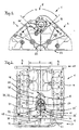
- Fig. 1 shows a crankcase 1 for an internal combustion engine, not shown facing the front.
- the end face becomes the one opposite the driven side Called page.
- It is a multi-cylinder internal combustion engine, the first of which Half of the cylinders in a row in a first cylinder bank 3 and the second Half of the cylinders are arranged one behind the other in a second cylinder bank 4.
- the cylinder banks 3 and 4 are arranged in a V-shape and form an intermediate space 5 at an angle ⁇ between 90 ° and 120 °.
- the intake air intake ducts of the cylinder heads, not shown here, for the cylinder banks 3 and 4 are arranged in the intermediate space 5.
- the exhaust ducts are located on the sides of the cylinder heads opposite the intake ports.
- a double spiral housing 12 in the middle a coolant pump 11 is installed from the viewing side.
- a short-circuit channel 26 can be seen.
- a first spiral 20 of the double spiral housing 12 is located directly under the coolant pump 11 and opens into a first longitudinal channel 18.
- a second spiral 21 of the double spiral housing 12 is located directly above the coolant pump 11 and opens into a second Longitudinal channel 19.
- the delivered coolant is divided into two by the spirals 20 and 21 Partial coolant flows divided. The one coming from the first spiral 20 is supplied the cylinder bank 3 with the associated cylinder head and that of the second spiral 21 coming supplies the cylinder bank 4 with the associated cylinder head with coolant.
- the partial coolant flows are shown schematically by arrows.
- a bearing bracket 22 of a crankshaft bearing is located below the coolant pump 11 the internal combustion engine.
- FIG. 2 shows the top view of the crankcase 1 in the direction of the intermediate space 5 is the cylinder bank 3 with four cylinders 2 and one arranged in series Coolant channel 33 and the cylinder bank 4 with four arranged in series Cylinders 2 and a coolant channel and 33 '.
- a housing 36 on a base plate 37.
- a cover 15 of the housing 36 is not shown.
- In the housing 36 are on the driven side 28 a coolant outlet 8, further towards the end 29 a middle one Chamber 32 with an annular sealing surface 27, then two coolant inlets 34 and 34 'and the short-circuit channel 26 are arranged in a coolant inlet 10.
- In the middle chamber 32 becomes a ring slide of a thermostatic valve, not shown here 13 installed.
- a mixing chamber 25 depending on the operating temperature of the internal combustion engine part of the chamber 32 serves as a mixing chamber 25.
- the double spiral housing 12 to which the longitudinal channels 18 and 19 are arranged, integrally formed on the housing 36.
- Crankcase 1, housing 36, base plate 37, double spiral housing 12 and longitudinal channels 18 and 19 are made in one piece.
- the coolant flow schematically represented by arrows in the internal combustion engine proceeds as follows:
- the coolant pump 11 draws coolant through the coolant inlet 10 and conveys it through the longitudinal channels 18 and 19 into the cylinder banks 3 and 4, further by cooling channels in crankcase 1 not shown in the cylinder heads, not shown, cooled according to the cross-flow principle through the coolant channels 33 and 33 'into the coolant inlets 34 and 34', from there through a channel in the cover 15 into the middle chamber 32.
- the coolant can the middle chamber 32 through the coolant outlet 8 and / or the short-circuit channel 26 leave.
- the arrangement of the cooler-side sections of the longitudinal channels 18 and 19 in one first camshaft drive level 30 and a second camshaft drive level 31 around the cylinder offset from cylinder bank 3 to cylinder bank 4 are shifted to each other in the longitudinal axis of the internal combustion engine, which enables Use of identical parts, such as identical camshafts, for the Cylinder banks 3 and 4.
- the central arrangement of the coolant pump 11 ensures same cooling channel lengths for both cylinder banks 3 and 4.
- the outer cooling circuit consists of a cooler 6, to which a flow line 7 and a return line 9 are arranged.
- the flow line 7 opens into a first connection piece 16 and the return line 9 in a second connection piece 17. Both connection pieces 16 and 17 are on the cover 15, the outer against the inner Coolant circuit delimited, arranged.
- the first one is in the internal coolant circuit - inside the internal combustion engine Connection piece 16 to the coolant outlet 8 and the second connection piece 17 assigned to the coolant inlet 10.
- the coolant inlet 10 leads to the coolant pump 11, which is mounted in the double spiral housing 12.
- a thermostatic valve housing 14 in the lid 15 and the middle chamber 32 there is a thermostatic valve 13, a ring slide thermostatic valve.
- the coolant circuit shown schematically in Fig. 3 works in addition to Description of Fig. 2 as follows:
- the coolant pump 11 sucks it Coolant from the external coolant circuit and or from the short-circuit channel 26 and supports it, as already described, through the internal combustion engine.
- the coolant is drained through here coolant channels 33 and 33 ', which cannot be seen, into the likewise not recognizable here Coolant inlets 34, 34 'and from here into the channel in the cover 15 back into the middle chamber 32 of the thermostatic valve housing 14 passed.
- Thermostatic valve 13 with a ring slide 35.
- the thermostatic valve 13 takes the Temperature of the incoming coolant, according to the operating state of the Internal combustion engine. Three operating states are available for the coolant circuit differentiated:
- the internal combustion engine is cold, the ring slide 35 is located in an upper one Position A and closes an inlet opening 24 to the coolant outlet channel 8.
- the cold coolant is passed into the short-circuit channel 26, which is a direct connection - Short circuit - to the coolant inlet duct 10.
- the coolant pump 11 pumps the coolant in a small cooling circuit via the short-circuit duct 26 directly back.
- the internal combustion engine is hot, the ring slide 35 of the thermostatic valve 13 pushes in the direction of short-circuit channel 26, a position B, and closes the Short-circuit channel 26 against the ring sealing surface 27.
- the hot coolant is through the inlet opening 24 to the coolant outlet channel 8 and through the connecting piece 16 and the flow line 7 conveyed to the cooler 6.
- the coolant is in the cooler 6 cooled and again from the coolant pump 11 via the return line 9 sucked in.
Landscapes
- Engineering & Computer Science (AREA)
- Chemical & Material Sciences (AREA)
- Combustion & Propulsion (AREA)
- Mechanical Engineering (AREA)
- General Engineering & Computer Science (AREA)
- Cylinder Crankcases Of Internal Combustion Engines (AREA)
Abstract
Description
- Fig. 1:
- Blick auf ein Kurbelgehäuse in Richtung Abtriebsseite;
- Fig. 2:
- Aufsicht auf das Kurbelgehäuse in Richtung Zwischenraum;
- Fig. 3:
- Vertikaler Längsschnitt durch das Kurbelgehäuse.
- 1
- Kurbelgehäuse
- 2
- Zylinder
- 3
- Erste Zylinderbank
- 4
- Zweite Zylinderbank
- 5
- Zwischenraum
- 6
- Kühler
- 7
- Vorlaufleitung
- 8
- Kühlmittelauslass
- 9
- Rücklaufleitung
- 10
- Kühlmitteleinlass
- 11
- Kühlmittelpumpe
- 12
- Doppelspiralgehäuse
- 13
- Thermostatventil
- 14
- Thermostatventilgehäuse
- 15
- Deckel
- 16
- Erster Anschlussstutzen
- 17
- Zweiter Anschlussstutzen
- 18
- Erster Längskanal
- 19
- Zweiter Längskanal
- 20
- Erste Spirale
- 21
- Zweite Spirale
- 22
- Lagerstuhl
- 23
- Kante
- 24
- Zulauföffnung
- 25
- Mischkammer
- 26
- Kurzschlusskanal
- 27
- Ringdichtfläche
- 28
- Getriebeseite
- 29
- Stirnseite
- 30
- Erste Nockenwellen-Antriebsebene
- 31
- Zweite Nockenwellen-Antriebsebene
- 32
- mittlere Kammer
- 33, 33'
- Kühlmittelkanal
- 34, 34'
- Kühlmittelzulauf
- 35
- Ringschieber
- 36
- Gehäuse
- 37
- Grundplatte
Claims (12)
- Kühlsystem mit einer Kühlmittelpumpe, für eine mit Flüssigkeit gekühlte Brennkraftmaschine mit einem Kurbelgehäuse, deren Zylinder in einer ersten Zylinderbank und in einer zweiten Zylinderbank V-förmig angeordnet sind und diese einen Zwischenraum einschließen, wobei ein Gehäuse in dem Zwischenraum vorgesehen ist, in dem ein Thermostatventil, ein Kühlmitteleinlass, ein Kühlmittelauslass und eine Mischkammer angeordnet sind, und das Gehäuse mit einem Deckel, an den ein erster und ein zweiter Anschlussstutzen angeordnet sind, abgedeckt ist,
dadurch gekennzeichnet, dass das Thermostatventil (13) ausschließlich von dem aus dem Kurbelgehäuse (1) zu einem Kühler (6) strömenden Kühlmittelstrom umströmt ist. - Kühlsystem nach Anspruch 1,
dadurch gekennzeichnet, dass die Kühlmittelpumpe (11) in dem Zwischenraum (5) an einer Stirnseite (29) und dahinter in Richtung Abtriebsseite (28) das Gehäuse (36) mit dem Deckel (15) angeordnet sind. - Kühlsystem nach Anspruch 1,
dadurch gekennzeichnet, dass die Kühlmittelpumpe (11) in einem Doppelspiralgehäuse (12) angeordnet ist. - Kühlsystem nach Anspruch 1,
dadurch gekennzeichnet, dass die erste Zylinderbank (3) von der Kühlmittelpumpe (11) über eine erste Spirale (20) des Doppelspiralgehäuses (12) und die zweite Zylinderbank (4) von der Kühlmittelpumpe (11) über eine zweite Spirale (21) des Doppelspiralgehäuses (12) mit Kühlmittel versorgt wird. - Kühlsystem nach mindestens einem der zuvor genannten Ansprüche,
dadurch gekennzeichnet, dass das Thermostatventil (13) und die Mischkammer (25) gemeinsam in einer mittleren Kammer (32) angeordnet sind. - Kühlsystem nach mindestens einem der zuvor genannten Ansprüche,
dadurch gekennzeichnet, dass die mittlere Kammer (32) über verschiedene Öffnungen mit dem Kühlmittelauslass (8), einem Kurzschlusskanal (26) und einem Kanal im Deckel (15) verbunden ist. - Kühlsystem nach mindestens einem der zuvor genannten Ansprüche,
dadurch gekennzeichnet, dass die mittlere Kammer (32) mit zwei Kühlmittelzuläufen (34, 34') durch den Kanal im Deckel (15) verbunden ist. - Kühlsystem nach mindestens einem der zuvor genannten Ansprüche,
dadurch gekennzeichnet, dass die mittlere Kammer (32) und der Kühlmitteleinlass (10) durch einen Kurzschlusskanal (26) verbunden sind. - Kühlsystem nach mindestens einem der zuvor genannten Ansprüche,
dadurch gekennzeichnet, dass der erste Anschlussstutzen (16) an den Kühlmittelauslass (8) und der zweite Anschlussstutzen (17) an den Kühlmitteleinlass (10) angeordnet sind. - Kühlsystem nach mindestens einem der zuvor genannten Ansprüche,
dadurch gekennzeichnet, dass das Gehäuse (36) an eine Grundplatte (37) angeformt ist. - Kühlsystem nach mindestens einem der zuvor genannten Ansprüche,
dadurch gekennzeichnet, dass das Gehäuse (36), die Grundplatte (37) und das Kurbelgehäuse (1) einstückig sind. - Kühlsystem nach Anspruch 1,
dadurch gekennzeichnet, dass das Thermostatventil (13) ein Ringschieberventil ist.
Applications Claiming Priority (2)
| Application Number | Priority Date | Filing Date | Title |
|---|---|---|---|
| DE10020485 | 2000-04-26 | ||
| DE2000120485 DE10020485A1 (de) | 2000-04-26 | 2000-04-26 | Kühlsystem für eine mit Flüssigkeit gekühlte Brennkraftmaschine |
Publications (2)
| Publication Number | Publication Date |
|---|---|
| EP1149994A2 true EP1149994A2 (de) | 2001-10-31 |
| EP1149994A3 EP1149994A3 (de) | 2003-03-12 |
Family
ID=7640015
Family Applications (1)
| Application Number | Title | Priority Date | Filing Date |
|---|---|---|---|
| EP01106208A Withdrawn EP1149994A3 (de) | 2000-04-26 | 2001-03-14 | Kühlsystem für eine mit Flüssigkeit gekühlte Brennkraftmaschine |
Country Status (2)
| Country | Link |
|---|---|
| EP (1) | EP1149994A3 (de) |
| DE (1) | DE10020485A1 (de) |
Cited By (2)
| Publication number | Priority date | Publication date | Assignee | Title |
|---|---|---|---|---|
| CN102482982A (zh) * | 2009-08-21 | 2012-05-30 | 丰田自动车株式会社 | 变流量水泵的控制装置 |
| EP2799684A3 (de) * | 2013-05-03 | 2016-04-06 | FERRARI S.p.A. | Brennkraftmaschine mit mechanisch getrennter Kühlmittelpumpe |
Families Citing this family (3)
| Publication number | Priority date | Publication date | Assignee | Title |
|---|---|---|---|---|
| DE102006032793B4 (de) * | 2006-07-14 | 2008-06-26 | Dr.Ing.H.C. F. Porsche Ag | Brennkraftmaschine |
| DE102012220447A1 (de) * | 2012-11-09 | 2014-06-12 | Bayerische Motoren Werke Aktiengesellschaft | Motorblock und Kühlmittelkreislauf für einen Verbrennungsmotor |
| DE102013021090B4 (de) * | 2013-12-18 | 2021-02-04 | Deutz Aktiengesellschaft | Kühlwassersteuerung |
Family Cites Families (4)
| Publication number | Priority date | Publication date | Assignee | Title |
|---|---|---|---|---|
| GB542009A (en) * | 1940-06-18 | 1941-12-22 | Arthur John Rowledge | Improvements in or relating to liquid-cooling systems for sleevevalve internal-combustion engines |
| JP2529826B2 (ja) * | 1986-03-20 | 1996-09-04 | ヤマハ発動機株式会社 | 内燃機関の冷却装置 |
| US5497734A (en) * | 1993-12-22 | 1996-03-12 | Nissan Motor Co., Ltd. | Cooling system for liquid-cooled engine |
| DE19803808A1 (de) * | 1998-01-31 | 1999-08-05 | Volkswagen Ag | Brennkraftmaschine |
-
2000
- 2000-04-26 DE DE2000120485 patent/DE10020485A1/de not_active Withdrawn
-
2001
- 2001-03-14 EP EP01106208A patent/EP1149994A3/de not_active Withdrawn
Cited By (3)
| Publication number | Priority date | Publication date | Assignee | Title |
|---|---|---|---|---|
| CN102482982A (zh) * | 2009-08-21 | 2012-05-30 | 丰田自动车株式会社 | 变流量水泵的控制装置 |
| EP2799684A3 (de) * | 2013-05-03 | 2016-04-06 | FERRARI S.p.A. | Brennkraftmaschine mit mechanisch getrennter Kühlmittelpumpe |
| US9970425B2 (en) | 2013-05-03 | 2018-05-15 | Ferrari S.P.A. | Internal combustion engine provided with a cooling pump that can be mechanically disconnected |
Also Published As
| Publication number | Publication date |
|---|---|
| EP1149994A3 (de) | 2003-03-12 |
| DE10020485A1 (de) | 2001-11-08 |
Similar Documents
| Publication | Publication Date | Title |
|---|---|---|
| DE2950905C2 (de) | Zylinderkopf für einen mehrzylindrigen Verbrennungsmotor | |
| DE19681509B4 (de) | Verbrennungskraftmaschine | |
| DE10125312A1 (de) | Integrales PCV-System | |
| DE2839199C2 (de) | Im Druckgießverfahren herstellbarer Zylinderkopf für wassergekühlte Brennkraftmaschinen | |
| DE4481079B4 (de) | Kühlsystem eines Verbrennungsmotors | |
| EP1474592B1 (de) | Wassergekühlte, mehrzylindrige brennkraftmaschine | |
| DE3123527A1 (de) | "hubkolben-brennkraftmaschine mit oelraeumen zur kuehlung" | |
| EP1761689B1 (de) | Brennkraftmaschine mit druckumlaufschmierung nach dem trockensumpfprinzip | |
| DE10222078B4 (de) | Mehrzylindermotor | |
| DE19641052C2 (de) | Vorrichtung zur Kühlung von Schmieröl eines V-Motors | |
| EP0819837B1 (de) | Kühlkreislauf einer Brennkraftmaschine | |
| DE19944017C2 (de) | Kühlungsaufbau eines Mehrzylindermotors | |
| EP1149994A2 (de) | Kühlsystem für eine mit Flüssigkeit gekühlte Brennkraftmaschine | |
| DE10021525A1 (de) | Kühlkreislauf für eine mehrzylindrige Brennkraftmaschine | |
| DE69001414T2 (de) | Kühlungsanlage für V-Brennkraftmaschine. | |
| DE2105657C3 (de) | Wärmetauscher | |
| EP0632190B1 (de) | Brennkraftmaschine mit zwei Zylinderreihen | |
| DE10021526C2 (de) | Anordnung zur Kühlung einer mehrzylindrigen Brennkraftmaschine | |
| DE4342799A1 (de) | Ölgekühlte Hubkolben-Brennkraftmaschine | |
| DE3629673A1 (de) | Brennkraftmaschine mit fluessigkeitsgekuehlter zylinderlaufbuchse | |
| EP0230017A2 (de) | Zylinderkopf | |
| EP0933510B1 (de) | Brennkraftmaschine | |
| DE4033796A1 (de) | Einkreiskuehlsystem fuer brennkraftmaschinen | |
| DE3615018C1 (en) | Valve stem guide for an exhaust valve | |
| DE2055902A1 (de) | Mehrzylinder-Brennkraftmaschine |
Legal Events
| Date | Code | Title | Description |
|---|---|---|---|
| PUAI | Public reference made under article 153(3) epc to a published international application that has entered the european phase |
Free format text: ORIGINAL CODE: 0009012 |
|
| AK | Designated contracting states |
Kind code of ref document: A2 Designated state(s): AT BE CH CY DE DK ES FI FR GB GR IE IT LI LU MC NL PT SE TR |
|
| AX | Request for extension of the european patent |
Free format text: AL;LT;LV;MK;RO;SI |
|
| PUAL | Search report despatched |
Free format text: ORIGINAL CODE: 0009013 |
|
| AK | Designated contracting states |
Kind code of ref document: A3 Designated state(s): AT BE CH CY DE DK ES FI FR GB GR IE IT LI LU MC NL PT SE TR Designated state(s): AT BE CH CY DE DK ES FI FR GB GR IE IT LI LU MC NL PT SE TR |
|
| AX | Request for extension of the european patent |
Extension state: AL LT LV MK RO SI |
|
| STAA | Information on the status of an ep patent application or granted ep patent |
Free format text: STATUS: THE APPLICATION HAS BEEN WITHDRAWN |
|
| 18W | Application withdrawn |
Effective date: 20030604 |