EP1149611A1 - Plaque de base d'une fixation pour planche de glisse - Google Patents
Plaque de base d'une fixation pour planche de glisse Download PDFInfo
- Publication number
- EP1149611A1 EP1149611A1 EP01110051A EP01110051A EP1149611A1 EP 1149611 A1 EP1149611 A1 EP 1149611A1 EP 01110051 A EP01110051 A EP 01110051A EP 01110051 A EP01110051 A EP 01110051A EP 1149611 A1 EP1149611 A1 EP 1149611A1
- Authority
- EP
- European Patent Office
- Prior art keywords
- binding
- foot
- engagement member
- footwear
- frame
- Prior art date
- Legal status (The legal status is an assumption and is not a legal conclusion. Google has not performed a legal analysis and makes no representation as to the accuracy of the status listed.)
- Granted
Links
Images

Classifications
-
- A—HUMAN NECESSITIES
- A63—SPORTS; GAMES; AMUSEMENTS
- A63C—SKATES; SKIS; ROLLER SKATES; DESIGN OR LAYOUT OF COURTS, RINKS OR THE LIKE
- A63C10/00—Snowboard bindings
- A63C10/24—Calf or heel supports, e.g. adjustable high back or heel loops
-
- A—HUMAN NECESSITIES
- A63—SPORTS; GAMES; AMUSEMENTS
- A63C—SKATES; SKIS; ROLLER SKATES; DESIGN OR LAYOUT OF COURTS, RINKS OR THE LIKE
- A63C10/00—Snowboard bindings
- A63C10/28—Snowboard bindings characterised by auxiliary devices or arrangements on the bindings
- A63C10/285—Pads as foot or binding supports, e.g. pads made of foam
-
- A—HUMAN NECESSITIES
- A63—SPORTS; GAMES; AMUSEMENTS
- A63C—SKATES; SKIS; ROLLER SKATES; DESIGN OR LAYOUT OF COURTS, RINKS OR THE LIKE
- A63C10/00—Snowboard bindings
- A63C10/02—Snowboard bindings characterised by details of the shoe holders
- A63C10/04—Shoe holders for passing over the shoe
-
- A—HUMAN NECESSITIES
- A63—SPORTS; GAMES; AMUSEMENTS
- A63C—SKATES; SKIS; ROLLER SKATES; DESIGN OR LAYOUT OF COURTS, RINKS OR THE LIKE
- A63C10/00—Snowboard bindings
- A63C10/16—Systems for adjusting the direction or position of the bindings
- A63C10/18—Systems for adjusting the direction or position of the bindings about a vertical rotation axis relative to the board
Definitions
- the present invention relates generally to a binding baseplate for a gliding board and, more particularly, to a snowboard binding baseplate.
- gliding board will refer generally to any of the foregoing boards as well as to other board-type devices which allow a rider to traverse a surface.
- inventive binding baseplate for a gliding board to which this patent is addressed is discussed below particularly in connection with a snowboard.
- present invention is not limited in this respect, and that the aspects of the present invention described below can be used in association with other types of gliding boards.
- a first type typically includes a baseplate adapted to receive a snowboard boot, an upright member called a "highback” (also known as a “lowback” and a “SKYBACK”) that is mounted at the rear of the binding and that acts as a lever to conduct forces induced by the rider through the baseplate and to the board, and a boot engagement systems such as one or more straps for securing the boot in the binding.
- a step-in binding also includes a baseplate and a highback (or the highback may be provided on the step-in binding boot), but does not employ a strap system.
- a step-in binding is characterized by one or more strapless engagement members which lock the boot into the binding.
- a handle or lever may be actuated to move one of the engagement members into and out of engagement with the snowboard boot or, instead, the engagement member may be automatically actuated upon stepping of the rider stepping into the binding.
- Binding baseplates are typically manufactured from a single material, dictating a particular performance property characterized by the stiffness of the baseplate.
- Some baseplates have been provided that include separate components with different stiffness properties, such as a metal or plastic base that is coupled to a stiffer metal heel hoop that supports a highback and an ankle strap. These baseplates, however, do not allow for selective adjustment of the stiffness of the binding and therefore do not allow a rider to vary the performance properties of the binding which may be desirable. Further, certain riders may desire a baseplate with a hybrid or a balance between these sometimes competing performance properties. That is, a binding that provides good power transmission and control yet also is characterized by a good feel and flexible response to rider induced forces.
- the present invention is therefore directed to a snowboard binding apparatus which overcomes the above-noted and other disadvantages of prior snowboard binding apparatuses.
- the present invention results in a snowboard binding having a baseplate with a toe end, a heel end, a lateral sidewall, and a medial sidewall.
- the baseplate is constructed and arranged to support a snowboard boot.
- the baseplate includes at least one location along each of the lateral and medial sidewalls for mounting at least one boot engagement member.
- the flexibility, in response to forces generated by a rider against the boot engagement member, of at least one mounting location along at least one of the medial and the lateral sides is selectively adjustable by a rider.
- a snowboard binding in an illustrative embodiment of the invention, includes a base which has a toe end, a heel end, a lateral side, and a medial side.
- the base is constructed and arranged to support a snowboard boot.
- the binding also includes at least one mount supported by the base.
- the mount is suitable for mounting at least one boot engagement member. At least one mount is subject to flexing in response to rider induced forces acting on the boot engagement member.
- the binding further includes a system supported by the binding for selectively adjusting the flex response of the mount to rider induced forces acting on the boot engagement member.
- a snowboard binding in another illustrative embodiment of the invention, includes a base having a toe end, a heel end, a lateral side, and a medial side.
- the base is formed from a material having a first stiffness.
- the binding also includes a mount for supporting a boot engagement member which holds down the front of a rider's foot.
- the mount is formed of a second material having a second stiffness which is different from the first stiffness.
- a snowboard binding in still another illustrative embodiment of the invention, includes a baseplate having a toe end, a heel end, a lateral sidewall, and a medial sidewall.
- the baseplate is also constructed and arranged to receive a snowboard boot.
- the binding also includes a boot engagement member mount adapted to receive a boot engagement member fixed to at least one of the lateral and medial sidewalls at a location proximate to the toe end and a location proximate to the heel end of the baseplate.
- the binding further includes at least one stiffener insert.
- the stiffener insert is placed between the toe end and the heel end fixation locations. The stiffener inserts allow the rider to adjust the flexing of the boot engagement member mount to rider induced forces acting on the boot engagement member.
- a snowboard binding in one embodiment, includes a baseplate having a medial side and a lateral side.
- the binding also includes a mount which is attached to the baseplate on at least one of the medial side and the lateral side.
- the binding also includes means for adjusting the flexibility of the mount in response to rider induced forces acting on the mount.
- a snowboard binding in another illustrative embodiment of the invention, includes a baseplate constructed and arranged to secure a snowboard boot to the snowboard.
- the baseplate has a flexibility that is selectively adjustable between a first fixed stiffness and a second fixed stiffness.
- the first stiffness is different from the second stiffness.
- a method for selectively adjusting the stiffness of a snowboard binding includes the steps of providing a binding adapted to attain one of a plurality of stiffnesses and reversibly adjusting the stiffness between the plurality of stiffnesses such that the stiffness may be changed from a first stiffness to a second stiffness and then to the first stiffness.
- the present invention is a baseplate for binding a foot to a board, and is particularly suitable for application as a snowboard binding baseplate.
- the binding baseplate may be tuned to provide a certain level and/or balance of one or more performance properties including, but not limited to power transmission, responsiveness, feel, and comfort. Accordingly, the binding baseplate may include localized regions of varying stiffness to provide a specific performance property. Consequently, the binding baseplate may include a specific stiffness characteristic at a location where the boot engagement members are mounted, providing a desired response of the binding baseplate to pulling forces that may be generated by the rider as she induces forces into the boot engagement members during turns, landing jumps, and otherwise during riding.
- the give or flex of the binding in response to the drawing force of the straps may be limited by stiffening the sidewall, so that there is little play, ensuring that the force of the rider's leg and foot movements are transmitted directly to the edge of the board.
- the binding may be tuned so that the sidewalls provide more give and flex in response to rider induced forces on the boot engaging straps, enhancing the feel of the rider, for example, as she rolls her foot against the strap while initiating and then leaning into a turn.
- tuning the stiffness of a binding baseplate will influence the performance of heel side and toe side turns.
- the rider controls the snowboard by applying force through the boot, along the highback and directly into the baseplate typically through the cooperation of a forward lean adjuster mounted on the highback and the baseplate heel hoop against which it seats, and subsequently into the board.
- Heel side turning also may be influenced by the lifting forces of the boot against a toe strap or other boot engagement member that is arranged to provide hold down of the front of the foot.
- force transmission on a heel side turn may be varied by manipulating the stiffness property of the heel hoop, and the mounting location of the heel hold down boot engagement member (i.e., ankle strap for a tray binding) as well as the mounting location for the toe end boot engagement member (i.e., toe strap for a tray binding).
- An increase in stiffness at one or more of these locations is believed to increase the responsiveness of the baseplate in heel side turns.
- a rider pivots her boot upwarldy about the ball of the foot, driving her boot against the ankle strap or other boot engagement member employed for heel hold down.
- the response of the baseplate here also, is affected by the stiffness of the baseplate where the ankle strap or other heel hold down arrangement is mounted.
- the overall stiffness profile of the baseplate will be affected by such localized tuning of stiffness properties which, too, will influence how the binding baseplate responds to rider induced forces.
- stiffness indicates a force-distance property curve associated with a particular material and/or a structural element
- stiffibility indicates a response of a particular material or a structural element to an applied force, e.g., a material of a particular stiffness flexes in response to an applied force.
- Stiffness of a binding baseplate component may be varied by altering the materials forming the component, the processes used to form the component, and any post processing treatments, and by the design of the component.
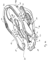
- FIGs. 1 and 2 An illustrative embodiment of the invention is illustrated in Figs. 1 and 2 and includes a baseplate 20 having a toe end 22, a heel end 24, a lateral sidewall 26, and a medial sidewall 28.
- a heel hoop 30 may be provided at the rear of the binding baseplate 20 which is arranged to receive the back portion of a rider's boot (not shown).
- a highback (not shown) may be mounted to the baseplate 20 or the heel hoop 30 and may include a forward lean adjuster for setting a desired angle of the highback. The forward lean adjuster may seat against the heel hoop 30, and may be locked in the seated arrangement if desired by appropriate linkage (not shown), to provide force transmission from the highback to the baseplate 20.
- One or more boot engagement members may be mounted to the binding, in the illustrated embodiment there are mounting locations for an ankle strap 32 and a toe strap 34.
- the particular number or arrangement of binding straps, or the selection of the type of boot engagement member is not critical to the invention here disclosed, and that the specific strap arrangement and mounting location therefore is provided merely for illustrative purposes, and the present invention is not limited to this or any particular boot engagement arrangement.
- the binding baseplate may also be implemented as a step-in snowboard binding where a locking mechanism directly or indirectly engages with complementary features on a snowboard boot and, thus, a boot engagement member may include, but is not limited to, a step-in type locking mechanism.
- the binding baseplate 20 may be formed with regions of varying stiffness. To address flex, the stiffness of the sidewalls 26, 28 of the baseplate 20 may be increased or lessened with respect to other regions of the baseplate 20 such as the lower base portion, although other points of reference in the baseplate 20 may similarly be employed. To encourage toe edge turning, the mount location for the illustrated ankle strap 32 is stiffer than other regions of the baseplate 20, again as an example the ankle strap mount may be stiffer than the bottom region of the baseplate 20. For heel side response, the principal force is induced through the highback and into the heel hoop 30, so providing a stiff heel hoop, as compared to the bottom or other region of the baseplate, will enhance that board maneuver. Although the illustrated baseplate includes localized variations in stiffness to achieve a desired property of lateral and medial flex, heel side response and toe side response, any one or more of the properties described, and other performance properties not discussed, may be targeted with the present invention.
- the binding baseplate 20 may be formed in a variety of manners to achieve the desired performance tuning.
- the baseplate 20 may be composed of a single material, but due to manufacturing processing or post fabrication treatment localized regions of the baseplate 20 may have different stiffness or other physical properties.
- the baseplate 20 may be formed of two or more different materials; by different materials, it is meant that materials having different chemical compositions or like materials that have been processed differently or otherwise transformed so that the two similarly composed materials are nonetheless characterized by at least one physical or mechanical property by which they differ.
- the binding baseplate 20 is formed of two components, a base 40 and a boot engagement member mount 42, which may be substantially U-shaped.
- the base 40 includes a floor 44 that is arranged for mounting to a snowboard and may be provided with an aperture 46 for receiving a hold down disc (not shown) in the well known manner for securing the baseplate via fasteners extending through holes in the disc that are threaded into inserts provided in the snowboard.
- the base 40 includes a lateral sidewall 48 and a medial sidewall 50 that are arranged to connect with the boot engagement member mount 42.
- the mount 42 may include a heel hoop 30.
- the mount 42 may include a location 52 for mounting a boot engagement member for holding down the rider's heel, such as the ankle strap 32.
- a mounting location 54 also is provided for the toe end strap 34 for restraining the front of the rider's foot.
- the mounting structure for the boot engagement straps are slots that receive a strap provided with an enlarged end that is prevented from passing through the slot. Tightening down respective strap pairs with a ratchet type buckle or other locking mechanism (not shown), draws the enlarged ends against the baseplate, securing straps and the encompassed boot within the binding.
- the present invention is not limited to this arrangement for mounting a strap to a baseplate and the use of fasteners inserted through an opening in the strap that passes through a compatible hole is the baseplate sidewall where it is secured by a nut or other fastener is contemplated as would be other arrangements that are apparent to one of skill in the art.
- the binding baseplate is not limited to strap bindings and a mount for a step-in or other arrangement for securing a boot to a binding also is within the present invention.
- the mount and heel hoop component 42 has a stiffness greater than or less than the stiffness of the base 40.
- the boot engagement member mount 42 and/or base 40 maybe formed of any suitable material such as PVC, glass-filled nylon, or other fiber-filled materials, or any metals. Variation in the size, length, and make-up of the fiber and/or the matrix composition and properties, may be applied to change the stiffness of these materials and the base and mount formed thereby. Further, the same material may be used for both the base 40 and the mount 42 with the difference in stiffness between the two components being due to a variation in the fiber employed or, perhaps, fabrication and/or post processing treatments. While several examples of materials and fabrication have been described above, it is to be appreciated that the baseplate may be fabricated with any suitable manufacturing process and/or material as would be apparent to one of skill in the art.
- the binding baseplate has been described where the boot engagement member mount 42 is stiffer than the base 40, the invention also contemplates having the baseplate stiffer than the boot engagement member mount.
- the mount for the boot engagement member directed to heel hold down may be stiffer than the mount for the boot engagement member directed to holding down the front of the rider's foot, or may be less stiff or may have the same stiffness, depending upon the desired performance properties of the binding baseplate or other factors including ease of manufacturing and conservation of product cost.
- the various elements such as the base 40, boot engagement member mount 42 and, if separate from the latter component, then also the heel hoop 30, are joined together by attachment elements. These junctions may be permanent or may by detachable allowing a rider to remove and either repair or replace a component. Further, by providing a removable component, the stiffness of the baseplate 20 may be varied by replacing an existing component with a new component having a different physical property.
- attachment devices including but not limited to, bolts, screws, rivets, cam attachment devices, and pins, may be employed as attachment devices to attach the mount 42 to the base 40.
- the components may also be permanently connected through adhesive, thermal fusion, ultrasonic welding, by molding the components together whether by insert molding or otherwise, and by other arrangements and techniques as would be apparent to one of skill in the art.
- the mount 42 includes a pair of flanges 60, 62, 67, 68 with holes 64 that are registrable with complementary holes 66 in the base 40 which may be secured by a fastener (not shown) such as a screw or the like. Similar constructs for receiving a fastener are provided at the toe end of the baseplate, securing the mount 42 and base 40 there as well.
- a pair of attachment locations are employed in the described embodiment at each of the toe and heel ends, the invention is not so limited and any number and arrangement of attachment junctions may be employed as would be apparent to one of skill in the art.
- the baseplate may be configured so that one or more attachment locations are positioned near a boot engagement member mount to enhance force transmission when a rider acts against the strap or other boot engagement member.
- the attachment devices 60, 62 are located directly below the strap attachment locations 52, 54 on the mount 42, so that the straps transmit force into the mount and directly into the base as the moment arm from the strap attachment location and the mount and base attachment location is reduced. Conversely, as the attachment devices are moved away from the strap attachment locations, the moment arm increases and force transmission is reduced. Not all of the attachment locations need be proximate a boot engagement mount in order for the noted benefits to occur.
- the binding baseplate 20 may be constructed and arranged so that the stiffness of localized regions and/or the entire stiffness profile of the baseplate 20 may be selectively adjusted by the rider. As shown in Fig. 1, the baseplate 20 may be arranged with any suitably shaped openings or recesses 70 that are adapted to receive stiffener inserts 72. By selectively placing the stiffener inserts 72 into such openings, the localized and overall stiffness of the baseplate may be changed. The size and/or shape of the apertures and opening may depend upon the desired stiffness range.
- the stiffener inserts 72 may be provided in a range of stiffener affecting properties so that a different insert having a different influence on the stiffness properties of the baseplate may be selectively inserted into a single, specific aperture by a rider. Further, the stiffness of a region may be increased or decreased by varying the thickness or surface texture of the baseplate at selected locations. The stiffness may also be established using various structural members or reliefs, such as ribs or grooves.
- the stiffener inserts 72 that also may be referred to as control elements, arc preferably removable so that a rider can readily adjust the overall baseplate stiffness by interchanging several control elements of varying stiffness.
- the stiffener inserts 72 are detachable plugs that may be locked into and removed from the apertures 70. Each plug may include an interlock, such as a barb, a tooth, an undercut or the like, that engages a corresponding feature, such as the periphery of the aperture, to retain the plug in the baseplate during anticipated riding conditions.
- the baseplate may be provided with two or more plugs of any suitable shape having different stiffness characteristics for each aperture to give a rider several options for baseplate stiffness.
- the stiffener insert 72 may take the form of a plug or panel insert on the sidewall.
- the baseplate stiffness may be minimized by removing each of the stiffener inserts 72 so that the baseplate may flex unconstrained.
- baseplate stiffness may be maximized by utilizing very stiff inserts 72 and ensuring that no openings are left vacant. The latter arrangement would appear suitable where high power transmission and quick board response is desired.
- Intermediate levels of baseplate stiffness may be achieved by plugging only some, but not all, of the openings.
- Stiffening can also be implemented by selective mechanical connection between the boot engagement member mount and the base.
- the mount 42 and the base 40 define a stiffening section 82.
- the stiffening section includes a projection or pedestal 80 on the base 40 which has an interface surface that cooperates with a corresponding interface surface on the mount 42.
- the base projection 80 is configured as a tongue that is received within a groove in a sidewall of the mount 42.
- One or more apertures 70 extend through the tongue and the sidewall defining the groove, allowing a fastener or stiffener insert to be inserted therethrough.
- the stiffness of the baseplate and, consequently the response of the baseplate to various rider induced forces, may then be adjusted selectively by the rider.
- a particular relative stiffness may be obtained by selecting a specific aperture as compared to another. And stiffness may be further enhanced by applying a mechanical fastener or stiffener insert into more than one of the registered sets of apertures.
- a single tongue and groove configuration is illustrated, multiple tongue and groove stations may as would be apparent to one of skill in the art.
- the mechanical fixation of the mount 42 to the base 40 is not limited to a fastener and aperture arrangement, and other mechanisms and designs are well suited to the present invention as would be apparent to one of skill in the art.
- stiffener inserts and/or mechanical fixation of the mount to the base allows the rider to adjust the stiffness of the binding to control one or more of lateral and medial flexing, toe side response, and heel side response,
- the rider may add or remove all or some of the stiffener inserts and/or mechanical fixation (whether all on one side or both sides) from the binding baseplate to selectively adjust the stiffness of the binding as desired.
- the rider may prefer a more flexible medial side, and thus remove all stiffener inserts from the medial side of the mount and base.
- the rider may increase the stiffness of the lateral side of the binding by inserting one or more stiffener inserts into the appropriate apertures. Combinations of various stiffener inserts of similar or differing properties in the apertures may also be employed to further adjust the flexibility in accordance with the rider's preferences.
- the stiffening section may be placed on the lateral and/or medial side of the base and mount between the toe end and the heel end fixation locations of the base 40 and the mount 42. In one embodiment, the stiffening section is placed substantially near the middle of the length of the binding, e.g., near the hold down disk of baseplate.
- a highback can be mounted to the base in any embodiment of the invention.
- the forward lean of any such highback could be adjusted by an appropriate forward lean adjuster.
- a hold-down interface can be provided. Such an interface may include means to adjust the stance angle of the binding relative to the gliding board.
Applications Claiming Priority (2)
| Application Number | Priority Date | Filing Date | Title |
|---|---|---|---|
| US560856 | 2000-04-28 | ||
| US09/560,856 US6485035B1 (en) | 2000-04-28 | 2000-04-28 | Binding baseplate for a gliding board |
Publications (2)
| Publication Number | Publication Date |
|---|---|
| EP1149611A1 true EP1149611A1 (fr) | 2001-10-31 |
| EP1149611B1 EP1149611B1 (fr) | 2003-05-28 |
Family
ID=24239638
Family Applications (1)
| Application Number | Title | Priority Date | Filing Date |
|---|---|---|---|
| EP01110051A Expired - Lifetime EP1149611B1 (fr) | 2000-04-28 | 2001-04-27 | Plaque de base d'une fixation pour planche de glisse |
Country Status (5)
| Country | Link |
|---|---|
| US (1) | US6485035B1 (fr) |
| EP (1) | EP1149611B1 (fr) |
| JP (1) | JP3081398U (fr) |
| AT (1) | ATE241410T1 (fr) |
| DE (1) | DE60100302T2 (fr) |
Cited By (4)
| Publication number | Priority date | Publication date | Assignee | Title |
|---|---|---|---|---|
| WO2004096387A2 (fr) * | 2003-04-25 | 2004-11-11 | Japana Co., Ltd | Fixation pour snowboard |
| WO2007064890A1 (fr) * | 2005-11-30 | 2007-06-07 | E. I. Du Pont De Nemours And Company | Fixation à partie d'emboîtage du talon ajustable |
| EP2014340A1 (fr) * | 2007-07-10 | 2009-01-14 | Skis Rossignol | Arceau arrière pour un dispositif de fixation de snowboard |
| EP2374513A1 (fr) * | 2010-04-12 | 2011-10-12 | Salomon S.A.S. | Dispositif d'accueil d'un pied ou d'une chaussure sur un engin de glisse |
Families Citing this family (5)
| Publication number | Priority date | Publication date | Assignee | Title |
|---|---|---|---|---|
| GB2412880B (en) * | 2003-01-24 | 2006-04-05 | Vans Inc | Toe ramp system |
| US6991240B2 (en) * | 2003-01-24 | 2006-01-31 | Vans, Inc. | Toe ramp system |
| WO2010124382A1 (fr) | 2009-04-30 | 2010-11-04 | Pelchat Jean-Francois | Système de fixation pour une planche de loisir |
| US9016714B2 (en) | 2009-04-30 | 2015-04-28 | Jf Pelchat Inc. | Binding system for recreational board |
| FR2988616B1 (fr) * | 2012-03-29 | 2016-03-18 | Rossignol Sa | Dispositif de fixation pour planche de glisse et planche equipee d’un tel dispositif |
Citations (2)
| Publication number | Priority date | Publication date | Assignee | Title |
|---|---|---|---|---|
| US5909894A (en) * | 1997-01-02 | 1999-06-08 | K-2 Corporation | Snowboard binding |
| US5975557A (en) * | 1996-01-17 | 1999-11-02 | Marker Deutschland Gmbh | Calf support on snowboard binding or snowboard boot |
Family Cites Families (41)
| Publication number | Priority date | Publication date | Assignee | Title |
|---|---|---|---|---|
| FR1601084A (fr) | 1968-03-07 | 1970-08-10 | ||
| DE2316868A1 (de) | 1972-04-17 | 1973-10-25 | Gertsch Ag | Skischuh |
| US3854743A (en) | 1973-08-02 | 1974-12-17 | H Hansen | Ski boot attachment frame |
| AT348908B (de) | 1976-10-04 | 1979-03-12 | Alber Franz Dipl Ing | Schibindung |
| US4652007A (en) | 1985-11-15 | 1987-03-24 | David Dennis | Releasable binding system for snowboarding |
| USRE33544E (en) | 1985-11-15 | 1991-02-26 | Look Alpine Products, Inc. | Releasable binding system for snowboarding |
| US4741550A (en) | 1985-11-15 | 1988-05-03 | David Dennis | Releasable binding system for snowboarding |
| US4772041A (en) | 1987-02-20 | 1988-09-20 | Klosterman James E | Simplified adjustable ski binding structure |
| US4964649A (en) | 1989-03-15 | 1990-10-23 | Chamberlin Justin M | Snowboard boot binder attachments |
| JPH0370043A (ja) | 1989-08-08 | 1991-03-26 | Nec Corp | プログラム動作検証方式 |
| IT1240260B (it) | 1990-03-06 | 1993-11-30 | Nordica Spa | Dispositivo di aggancio di una calzatura ad un attrezzo soportivo |
| US5172924A (en) | 1991-03-27 | 1992-12-22 | Barci Robert S | Hard shell boot snowboard bindings and system |
| US5505477A (en) | 1993-07-19 | 1996-04-09 | K-2 Corporation | Snowboard binding |
| US5577756A (en) | 1993-07-19 | 1996-11-26 | Caron; Jeffrey E. | Snowboard binding system |
| US5549310A (en) | 1993-07-19 | 1996-08-27 | K-2 Corporation | In-line roller skate with improved frame assembly |
| FR2722373B1 (fr) | 1994-07-13 | 1996-10-04 | Salomon Sa Societe Anonyme | Ensemble d'une chaussure et d'un element de retenue, notamment pour la pratique du ski |
| FR2722421B1 (fr) | 1994-07-13 | 1996-09-27 | Salomon Sa Societe Anonyme | Element de fixation de ski alpin |
| US5512000A (en) | 1994-08-23 | 1996-04-30 | H.O. Sports, Inc. | Shock absorbing binding |
| IT239582Y1 (it) | 1995-06-21 | 2001-03-05 | Nordica Spa | Dispositivo di adattamento della calzata, particolarmente per attacchidi calzature sportive |
| US5713587A (en) | 1995-08-11 | 1998-02-03 | Morrow Snowboards, Inc. | Attachment system for snowboards |
| US5743551A (en) | 1995-09-06 | 1998-04-28 | Salomon S.A. | Retention element for a boot on a gliding board |
| FR2741544B1 (fr) | 1995-11-29 | 1997-12-19 | Rossignol Sa | Ski equipe d'un dispositif destine a adapter la position transversale d'une fixation en fonction des impulsions du skieur |
| US5624291A (en) | 1995-12-14 | 1997-04-29 | Mcclaskey; Darryl W. | Wake board bindings |
| FR2746604B1 (fr) | 1996-03-29 | 1998-05-29 | Salomon Sa | Dispositif de retenue d'une chaussure sur une planche avec element d'appui dorsal articule |
| JPH09276473A (ja) | 1996-04-08 | 1997-10-28 | Tokyo Ichitsuru:Kk | スノーボード用バインディング |
| FR2749484B1 (fr) | 1996-06-06 | 1998-08-07 | Salomon Sa | Chaussure de sport destinee a la pratique du surf sur la neige |
| IT1283817B1 (it) | 1996-08-21 | 1998-04-30 | Pida S R L | Attacco per tavola da neve |
| FR2752685B1 (fr) | 1996-08-30 | 1998-09-25 | Rossignol Sa | Chaussure pour planche de glisse |
| JP3944914B2 (ja) | 1996-10-14 | 2007-07-18 | セイコーエプソン株式会社 | 累進多焦点レンズの製造方法 |
| US5758895A (en) | 1996-10-21 | 1998-06-02 | Bumgarner; Scott Edward | Snowboard binding straps and locking bar assembly |
| US6027136A (en) | 1997-01-08 | 2000-02-22 | The Burton Corporation | System for preventing toe-edge travel of a hi-back |
| ES2210712T3 (es) | 1997-01-17 | 2004-07-01 | Vans, Inc. | Un sistema de sujecion de tobillo de botas de snowbord. |
| DE19710436A1 (de) | 1997-03-13 | 1998-09-17 | Kuchler Walter | Bindung für Snowboard, Monoski o. dgl. |
| US5901975A (en) | 1997-03-18 | 1999-05-11 | Eric T. Phipps | Vertically flexible snowboard binding |
| US5971407A (en) | 1997-03-26 | 1999-10-26 | Sims Sports, Inc. | Snowboard binding |
| US5984343A (en) | 1997-04-08 | 1999-11-16 | Robert J. Harrington | Sliding apparatus having adjustable flexion and torsion characteristics |
| US5855390A (en) | 1997-09-17 | 1999-01-05 | Hassell; Christopher S. | Laterally flexible snowboard binding system |
| JPH11206952A (ja) | 1998-01-26 | 1999-08-03 | Akira Sasaki | スノーボード用ブーツの固定装置 |
| US6557865B1 (en) | 1998-10-09 | 2003-05-06 | The Burton Corporation | Highback with adjustable stiffness |
| IT1302744B1 (it) | 1998-11-12 | 2000-09-29 | Piva Calzaturificio | Attacco da snowboard con base a rigidezza regolabile |
| US6257997B1 (en) | 1999-08-18 | 2001-07-10 | Alliance Design And Development Group | Adjusting stiffness and flexibility in sports equipment |
-
2000
- 2000-04-28 US US09/560,856 patent/US6485035B1/en not_active Expired - Lifetime
-
2001
- 2001-04-26 JP JP2001002545U patent/JP3081398U/ja not_active Expired - Fee Related
- 2001-04-27 AT AT01110051T patent/ATE241410T1/de not_active IP Right Cessation
- 2001-04-27 DE DE60100302T patent/DE60100302T2/de not_active Expired - Fee Related
- 2001-04-27 EP EP01110051A patent/EP1149611B1/fr not_active Expired - Lifetime
Patent Citations (2)
| Publication number | Priority date | Publication date | Assignee | Title |
|---|---|---|---|---|
| US5975557A (en) * | 1996-01-17 | 1999-11-02 | Marker Deutschland Gmbh | Calf support on snowboard binding or snowboard boot |
| US5909894A (en) * | 1997-01-02 | 1999-06-08 | K-2 Corporation | Snowboard binding |
Cited By (10)
| Publication number | Priority date | Publication date | Assignee | Title |
|---|---|---|---|---|
| WO2004096387A2 (fr) * | 2003-04-25 | 2004-11-11 | Japana Co., Ltd | Fixation pour snowboard |
| WO2004096387A3 (fr) * | 2003-04-25 | 2005-03-10 | Japana Co Ltd | Fixation pour snowboard |
| WO2007064890A1 (fr) * | 2005-11-30 | 2007-06-07 | E. I. Du Pont De Nemours And Company | Fixation à partie d'emboîtage du talon ajustable |
| US7520526B2 (en) | 2005-11-30 | 2009-04-21 | E.I. Du Pont De Nemours | Binding with adjustable heel-cup frame |
| EP2014340A1 (fr) * | 2007-07-10 | 2009-01-14 | Skis Rossignol | Arceau arrière pour un dispositif de fixation de snowboard |
| FR2918573A1 (fr) * | 2007-07-10 | 2009-01-16 | Skis Rossignol Soc Par Actions | Arceau arrriere pour un dispositif de fixation de snowboard. |
| US8960710B2 (en) | 2007-07-10 | 2015-02-24 | Skis Rossignol | Rear hoop for a snowboard binding |
| EP2374513A1 (fr) * | 2010-04-12 | 2011-10-12 | Salomon S.A.S. | Dispositif d'accueil d'un pied ou d'une chaussure sur un engin de glisse |
| FR2958556A1 (fr) * | 2010-04-12 | 2011-10-14 | Salomon Sas | Dispositif d'accueil d'un pied ou d'une chaussure sur un engin de glisse. |
| US8573631B2 (en) | 2010-04-12 | 2013-11-05 | Salomon S.A.S. | Device for receiving a foot or a boot on a gliding apparatus |
Also Published As
| Publication number | Publication date |
|---|---|
| DE60100302T2 (de) | 2004-03-18 |
| EP1149611B1 (fr) | 2003-05-28 |
| ATE241410T1 (de) | 2003-06-15 |
| JP3081398U (ja) | 2001-11-02 |
| US6485035B1 (en) | 2002-11-26 |
| DE60100302D1 (de) | 2003-07-03 |
Similar Documents
| Publication | Publication Date | Title |
|---|---|---|
| US6231057B1 (en) | Highback with an adjustable shape | |
| US7566062B2 (en) | Highback formed of multiple materials | |
| US5894684A (en) | Snowboard boot ankle support device | |
| US5713587A (en) | Attachment system for snowboards | |
| US6742800B2 (en) | Snowboard binding system | |
| US6467795B1 (en) | Snowboard binding with highback | |
| EP0749766B1 (fr) | Fixation pour attacher une chaussure à une plaque | |
| EP0979045B1 (fr) | Systeme d'appui-mollet actif destine a une chaussure de planche a neige | |
| JP3539909B2 (ja) | スノーボードブーツ用アクティブハイバックシステム及びスノーボードブーツ | |
| JP2001516628A (ja) | スノーボード用の改良型ブーツ・ビンディング装置 | |
| WO2001049381A1 (fr) | Support montant a soutien de jambe en forme d'aile | |
| US6557865B1 (en) | Highback with adjustable stiffness | |
| JP2003235602A (ja) | スポーツ靴用ストラップアセンブリ | |
| US20070187927A1 (en) | Binding with adjustable heel-cup frame | |
| EP1149611B1 (fr) | Plaque de base d'une fixation pour planche de glisse | |
| EP1572301A1 (fr) | Fixation de planche a neige dotee d'une sangle talonniere de suspension | |
| US6543793B1 (en) | Highback formed of multiple materials | |
| EP2455143A1 (fr) | Fixation de planche de glisse avec portion médiane ou latérale mobile |
Legal Events
| Date | Code | Title | Description |
|---|---|---|---|
| PUAI | Public reference made under article 153(3) epc to a published international application that has entered the european phase |
Free format text: ORIGINAL CODE: 0009012 |
|
| 17P | Request for examination filed |
Effective date: 20010427 |
|
| AK | Designated contracting states |
Kind code of ref document: A1 Designated state(s): AT CH DE FR IT LI Kind code of ref document: A1 Designated state(s): AT BE CH CY DE DK ES FI FR GB GR IE IT LI LU MC NL PT SE TR |
|
| AX | Request for extension of the european patent |
Free format text: AL;LT;LV;MK;RO;SI |
|
| 17Q | First examination report despatched |
Effective date: 20020114 |
|
| AKX | Designation fees paid |
Free format text: AT CH DE FR IT LI |
|
| GRAH | Despatch of communication of intention to grant a patent |
Free format text: ORIGINAL CODE: EPIDOS IGRA |
|
| GRAH | Despatch of communication of intention to grant a patent |
Free format text: ORIGINAL CODE: EPIDOS IGRA |
|
| GRAA | (expected) grant |
Free format text: ORIGINAL CODE: 0009210 |
|
| AK | Designated contracting states |
Designated state(s): AT CH DE FR IT LI |
|
| REG | Reference to a national code |
Ref country code: CH Ref legal event code: EP |
|
| REF | Corresponds to: |
Ref document number: 60100302 Country of ref document: DE Date of ref document: 20030703 Kind code of ref document: P |
|
| REG | Reference to a national code |
Ref country code: CH Ref legal event code: NV Representative=s name: KATZAROV S.A. |
|
| ET | Fr: translation filed | ||
| PLBE | No opposition filed within time limit |
Free format text: ORIGINAL CODE: 0009261 |
|
| STAA | Information on the status of an ep patent application or granted ep patent |
Free format text: STATUS: NO OPPOSITION FILED WITHIN TIME LIMIT |
|
| 26N | No opposition filed |
Effective date: 20040302 |
|
| PGFP | Annual fee paid to national office [announced via postgrant information from national office to epo] |
Ref country code: FR Payment date: 20060411 Year of fee payment: 6 |
|
| PGFP | Annual fee paid to national office [announced via postgrant information from national office to epo] |
Ref country code: AT Payment date: 20060418 Year of fee payment: 6 Ref country code: CH Payment date: 20060418 Year of fee payment: 6 |
|
| PGFP | Annual fee paid to national office [announced via postgrant information from national office to epo] |
Ref country code: DE Payment date: 20060419 Year of fee payment: 6 |
|
| REG | Reference to a national code |
Ref country code: CH Ref legal event code: PL |
|
| PG25 | Lapsed in a contracting state [announced via postgrant information from national office to epo] |
Ref country code: DE Free format text: LAPSE BECAUSE OF NON-PAYMENT OF DUE FEES Effective date: 20071101 |
|
| PG25 | Lapsed in a contracting state [announced via postgrant information from national office to epo] |
Ref country code: CH Free format text: LAPSE BECAUSE OF NON-PAYMENT OF DUE FEES Effective date: 20070430 Ref country code: AT Free format text: LAPSE BECAUSE OF NON-PAYMENT OF DUE FEES Effective date: 20070427 Ref country code: LI Free format text: LAPSE BECAUSE OF NON-PAYMENT OF DUE FEES Effective date: 20070430 |
|
| PG25 | Lapsed in a contracting state [announced via postgrant information from national office to epo] |
Ref country code: FR Free format text: LAPSE BECAUSE OF NON-PAYMENT OF DUE FEES Effective date: 20070430 |
|
| PGFP | Annual fee paid to national office [announced via postgrant information from national office to epo] |
Ref country code: IT Payment date: 20081025 Year of fee payment: 8 |
|
| PG25 | Lapsed in a contracting state [announced via postgrant information from national office to epo] |
Ref country code: IT Free format text: LAPSE BECAUSE OF NON-PAYMENT OF DUE FEES Effective date: 20090427 |