EP1149399B1 - Contactor - Google Patents
Contactor Download PDFInfo
- Publication number
- EP1149399B1 EP1149399B1 EP00902235A EP00902235A EP1149399B1 EP 1149399 B1 EP1149399 B1 EP 1149399B1 EP 00902235 A EP00902235 A EP 00902235A EP 00902235 A EP00902235 A EP 00902235A EP 1149399 B1 EP1149399 B1 EP 1149399B1
- Authority
- EP
- European Patent Office
- Prior art keywords
- contactor
- arresting
- engagement
- locking pin
- house
- Prior art date
- Legal status (The legal status is an assumption and is not a legal conclusion. Google has not performed a legal analysis and makes no representation as to the accuracy of the status listed.)
- Expired - Lifetime
Links
Images
Classifications
-
- H—ELECTRICITY
- H01—ELECTRIC ELEMENTS
- H01H—ELECTRIC SWITCHES; RELAYS; SELECTORS; EMERGENCY PROTECTIVE DEVICES
- H01H50/00—Details of electromagnetic relays
- H01H50/02—Bases; Casings; Covers
- H01H50/04—Mounting complete relay or separate parts of relay on a base or inside a case
- H01H50/041—Details concerning assembly of relays
- H01H50/045—Details particular to contactors
-
- H—ELECTRICITY
- H01—ELECTRIC ELEMENTS
- H01H—ELECTRIC SWITCHES; RELAYS; SELECTORS; EMERGENCY PROTECTIVE DEVICES
- H01H50/00—Details of electromagnetic relays
- H01H50/02—Bases; Casings; Covers
- H01H50/04—Mounting complete relay or separate parts of relay on a base or inside a case
Definitions
- the present invention relates to a relay or contactor, wherein measures are taken to facilitate assembly and disassembly in installation and maintenance.
- the inventive contactor also contributes to better security in operation and service. More specifically, the invention suggests a contactor that is structured to permit assembly and disassembly only in a specified sequential operation.
- Typical contactors of this kind has an electric magnet for non-manual operation of contacts to close and break, respectively, an electric current circuit, e.g. a triple-pole alternating current. Control current is supplied to a coil of the electric magnet, and a magnet movement is employed for closing or breaking the electric circuit.
- the contactor also has secondary contacts and current connections for the control current, that may be controlled manually or electronically.
- Contactors of the kind are employed in industrial applications as motor switches, e.g., and are commonly installed at supply central units to which system current and control current is supplied to feed multiple current consumers.
- the central units may receive a large number of electric conductors, so that major caution is required in service operations for maintenance, repairs or for replacing worn out components.
- Such service may expose technicians and other personnel to a latent risk of injury.
- switches for the control power are situated away from the central unit, so that service personnel may not at all times be in complete control of the status of the electric magnet. This situation involves the risk of the system power being unintentionally supplied during service, e.g. when replacing the main contacts of the contactor.
- Such a contactor is known e.g. from the document US-A-3 651 437 .
- the object of this invention is to meet above said desires, and to solve the problems arising therefrom.
- a contactor comprising a contactor enclosure that is sequentially detachable in two successive steps, each step depending from the other.
- a first step the components of the control power circuit as well as the contacts for the system power circuit are unitarily detached in order to permit access to the system power contacts.
- the contacts of the control power circuit are still enclosed by a detachable part of the contactor enclosure.
- a second step access is made to the components of the control power circuit by opening the detachable part of the enclosure.
- a main feature of the invention is that the two steps for opening the enclosure are both controlled by a number of common locking elements, formed to engage alternative arresting seats for a partial or a complete access to internal components and operative details of the contactor, thereby avoiding an unintentional supply of system power when the contactor enclosure is detached in said first step.
- the contactor 1 is an electromagnetic relay operative to control a triple-pole system power current.
- the operative elements of the contactor 1 are designed to provide better maintenance security and effectiveness, in accordance with this invention.
- said contactor 1 comprises connections for system power, contacts, electric magnet, coil and connections for the control power as known per se, and may further include elements for adapting the contactor to a specified application.
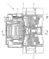
- a contactor enclosure comprising three main components: a house 2 permanently incorporated in the system current path, a removable casing 3 accommodated by the house, and a cover 4 that seales the casing.
- the contactor house 2 is permanently positioned in the current path through fastening means, not further shown, so that a bottom side of the house is seated on a support structure.
- Input and output connection means 5,6 are accommodated in the bottom area of the house 2, as best seen in fig. 1, for connecting the system power phase conductors to the conductor 1.
- the connection means 5,6 are two-part elements that are fixedly mounted by screws in the house 2, and may preferably be located in disconnection cells formed in the house 2 and equipped with arc-shielding means.
- connection means 5,6 cooperates with a separate contact 7.
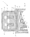
- the contact 7 is supported to be movable from a circuit breaking position shown in figs. 1 and 2, to a circuit closing position wherein the contact 7 is moved to engagement with the connection means 5,6.
- the contacts 7 are supported in a circuit breaking bridge 8, that is movable in the house 2 against the force of springs 9.
- the springs 9 are seated in spring guides 10 extending out from the bottom of the house 2.
- the breaking bridge 8 is bridge-shaped to reach transversely over the contactor. Shoulders 11, acting as seats for the springs 9, are formed in the bottom surface of the breaking bride 8.
- Each contact 7 is supported in a socket 12, extending out from the bottom surface of the breaking bridge, and seated to be biased by a spring (not further shown).
- the socket 12 is integrally formed in the house 2 to provide separate paths for the system power through the contactor 1.
- the breaking bridge 8 is formed with a pair of columns 13,14 extending out from the upper surface of the bridge and passing through slots 15, formed in opposite sides of the casing 3 which is removably attached to the house 2. Between upper ends of the columns 13,14 there is supported an electromagnet armature 16, resting on seats 17 formed on the columns or in separate carriers, engaging the columns to transfer the armature movement to the breaking bridge and the contacts 7 in a circuit closing motion.
- An electromagnet armature having a magnetized core 18 and a coil 19 is arranged in the bottom area of casing 3.
- Flexible or elastomer inserts 20 may be arranged between the core and the bottom of the casing in order to permit some relative motion there between.
- the house 2, casing 3 and breaking bridge 8 are suitably formed to guide and facilitate the breaking bridge motion between the circuit closing and breaking positions.
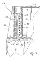
- the casing 3 has a surrounding wall 21, wherein recesses 22 are formed in each corner of the casing (see fig. 3).
- Each said recess 22 receives a leg 23 depending from the corners of the cover 4.
- the legs 23 In attached position, wherein the cover 4 sealingly rests on the upper edge of the surrounding wall 21, the legs 23 bear against the bottom of the casing, in the bottom areas that reach into the recesses.
- the inventive teachings are not limited to a certain number of legs 23, preferably though, at least two such legs are provided.
- the cover 4 and casing 3 has a common locking element or locking pin 24 that runs through the leg 23.
- the locking pin 24 comprises a shaft 25, formed in the lower end with a hook 26 that is angled to extend substantially perpendicular from the shaft.
- a helical spring 27 is supported on the shaft, between said hook 26 and a slotted head 28 formed in the opposite end of the shaft.
- the locking pin 24 In the attached position of the contactor enclosure, the locking pin 24 reaches through the cover 4 to engage an arresting seat 29, formed in the housing 2 and cooperating with the hook 26 of the locking pin.
- the locking pin is spring biased in the arrested position as the helical spring is compressed between the head 28 and a bottom area 30, formed in the lower end of the leg 23. This way, the cover 4, the casing 3 and the house 2 are locked together by the common locking pin to provide the sealed contactor enclosure 1.
- the casing 3 and the cover 4 may be detached from the house 2 in order to expose the connection means 5,6 that are accommodated in the bottom area of the house 2.
- the breaking bridge 8 with contacts 7 as well as the control circuit elements such as electric magnet, coil and supply conductors for control power, will be detached as a unit.
- the control circuit elements are still enclosed by the walls and bottom of the casing 3 and the cover 4, as the locking pin is in engagement with the second arresting seat formed in the bottom of the casing.
- the hook 26 is released from the arresting seat 31 of the casing 3, and the cover 4 is detachable to permit access to the operative elements of the control circuit in a second step of detachment.
- the arresting seats 29 and 31 are formed with elongate apertures 29' and 31', respectively, extending angularly separated in radial directions from the turning center of the locking pin so as to provide a passage for the locking pin through either aperture when rotated to the appropriate position, and when further rotated, to permit passage through the other aperture.
- the locking pin is spring biased to engage the material of the house and casing, respectively.
- the arresting seats will be defined in the material, e.g. through recesses, such that a definite indication of the locking pin's arrested position is provided, and thus an unintentional twisting of the locking pin 24 is prevented. As will be seen from fig.
- the locking pin is automatically positioned for engagement with the arresting seat 31, when being rotated out of engagement with the arresting seat 29.
- the apertures are oriented in opposite radial directions from the locking pin turning center, even though alternative angular displacement lies within the teachings of the invention.
- Attachment or assembly of the contactor enclosure is achieved by performing the two steps in reversed order. Accordingly, in a first step the cover 4 is attached to the casing 3 by turning the locking pin to engage the second arresting seat 31 of the cover, and successively in a second step the casing, carrying the breaking bridge 8, is attached to the house 2 by turning the locking pin to engage the first arresting seat 29 of the house 2.
Landscapes
- Physics & Mathematics (AREA)
- Electromagnetism (AREA)
- Switch Cases, Indication, And Locking (AREA)
- Breakers (AREA)
- Emergency Protection Circuit Devices (AREA)
- Materials For Medical Uses (AREA)
- Contacts (AREA)
Applications Claiming Priority (3)
| Application Number | Priority Date | Filing Date | Title |
|---|---|---|---|
| SE9900280 | 1999-01-28 | ||
| SE9900280A SE513442C2 (sv) | 1999-01-28 | 1999-01-28 | Kontaktor |
| PCT/SE2000/000054 WO2000045406A1 (en) | 1999-01-28 | 2000-01-13 | Contactor |
Publications (2)
| Publication Number | Publication Date |
|---|---|
| EP1149399A1 EP1149399A1 (en) | 2001-10-31 |
| EP1149399B1 true EP1149399B1 (en) | 2007-10-10 |
Family
ID=20414273
Family Applications (1)
| Application Number | Title | Priority Date | Filing Date |
|---|---|---|---|
| EP00902235A Expired - Lifetime EP1149399B1 (en) | 1999-01-28 | 2000-01-13 | Contactor |
Country Status (9)
| Country | Link |
|---|---|
| US (1) | US6566989B1 (enExample) |
| EP (1) | EP1149399B1 (enExample) |
| JP (1) | JP4514961B2 (enExample) |
| CN (1) | CN1213451C (enExample) |
| AT (1) | ATE375598T1 (enExample) |
| AU (1) | AU2336400A (enExample) |
| DE (1) | DE60036687T2 (enExample) |
| SE (1) | SE513442C2 (enExample) |
| WO (1) | WO2000045406A1 (enExample) |
Families Citing this family (1)
| Publication number | Priority date | Publication date | Assignee | Title |
|---|---|---|---|---|
| US7391285B2 (en) * | 2003-10-30 | 2008-06-24 | Avago Technologies Wireless Ip Pte Ltd | Film acoustically-coupled transformer |
Family Cites Families (12)
| Publication number | Priority date | Publication date | Assignee | Title |
|---|---|---|---|---|
| DE1625369A1 (de) * | 1967-11-27 | 1970-07-16 | Honeywell Gmbh | Vorrichtung zum Befestigen mehrerer Platten im Abstand uebereinander |
| US3651437A (en) * | 1971-03-19 | 1972-03-21 | Matsushita Electric Works Ltd | Electromagnetic contactor |
| JPS54181273U (enExample) * | 1978-06-14 | 1979-12-21 | ||
| JPS5855550Y2 (ja) * | 1978-09-07 | 1983-12-20 | 富士電機株式会社 | 電磁接触器 |
| DE3032724A1 (de) * | 1980-08-30 | 1982-04-29 | Brown, Boveri & Cie Ag, 6800 Mannheim | Elektromagnetisches schaltgeraet |
| FR2605150B1 (fr) * | 1986-10-09 | 1988-12-30 | Telemecanique Electrique | Appareil electro-magnetique de commutation ayant des interrupteurs interchangeables |
| FR2638563B1 (fr) * | 1988-10-27 | 1990-12-14 | Telemecanique Electrique | Dispositif de securite pour appareil de commutation realise par l'assemblage de plusieurs elements modulaires amovibles |
| FR2643503B1 (fr) * | 1989-02-21 | 1991-05-10 | Telemecanique Electrique | Appareil contacteur a interrupteurs proteges |
| US5239144A (en) * | 1992-02-07 | 1993-08-24 | Siemens Energy & Automation, Inc. | Circuit breaker trip unit interlock |
| DE4341330C1 (de) * | 1993-12-03 | 1995-04-20 | Siemens Ag | Elektromagnetisches Schaltgerät |
| JP3336814B2 (ja) * | 1995-05-23 | 2002-10-21 | 富士電機株式会社 | 電磁接触器ケースの取付機構 |
| FR2736752B1 (fr) * | 1995-07-13 | 1997-08-22 | Schneider Electric Sa | Appareil interrupteur de type contacteur-disjoncteur |
-
1999
- 1999-01-28 SE SE9900280A patent/SE513442C2/sv unknown
-
2000
- 2000-01-13 AU AU23364/00A patent/AU2336400A/en not_active Abandoned
- 2000-01-13 AT AT00902235T patent/ATE375598T1/de not_active IP Right Cessation
- 2000-01-13 JP JP2000596581A patent/JP4514961B2/ja not_active Expired - Lifetime
- 2000-01-13 US US09/890,123 patent/US6566989B1/en not_active Expired - Lifetime
- 2000-01-13 WO PCT/SE2000/000054 patent/WO2000045406A1/en not_active Ceased
- 2000-01-13 DE DE60036687T patent/DE60036687T2/de not_active Expired - Lifetime
- 2000-01-13 EP EP00902235A patent/EP1149399B1/en not_active Expired - Lifetime
- 2000-01-13 CN CNB008032203A patent/CN1213451C/zh not_active Expired - Lifetime
Also Published As
| Publication number | Publication date |
|---|---|
| SE513442C2 (sv) | 2000-09-11 |
| EP1149399A1 (en) | 2001-10-31 |
| SE9900280D0 (sv) | 1999-01-28 |
| JP4514961B2 (ja) | 2010-07-28 |
| CN1367932A (zh) | 2002-09-04 |
| AU2336400A (en) | 2000-08-18 |
| US6566989B1 (en) | 2003-05-20 |
| DE60036687T2 (de) | 2008-07-24 |
| ATE375598T1 (de) | 2007-10-15 |
| WO2000045406A1 (en) | 2000-08-03 |
| DE60036687D1 (de) | 2007-11-22 |
| JP2002536785A (ja) | 2002-10-29 |
| CN1213451C (zh) | 2005-08-03 |
| SE9900280L (sv) | 2000-07-29 |
Similar Documents
| Publication | Publication Date | Title |
|---|---|---|
| CA2155406C (en) | Connector assembly for a motor control unit | |
| FI89988B (fi) | Med skyddsanordning och faestanordning foersedd elektrisk kopplingsanordning | |
| US6411489B1 (en) | Electromagnetic operator for an electrical contactor and method for controlling same | |
| CA2155405C (en) | Interlock mechanism for a motor control unit | |
| KR900006145B1 (ko) | 상호교환가능한 전자개폐스위치장치 | |
| US7772945B2 (en) | Electrical switching device | |
| KR101670011B1 (ko) | 무정전 교체가 가능한 분전반의 부스바 접속 키트 | |
| US3544929A (en) | Industrial control relay | |
| US3354415A (en) | Multiple contact electromagnetically actuated switch and accessories therefor | |
| EP1149399B1 (en) | Contactor | |
| US5557498A (en) | Switching apparatus including a displaceable disconnecting device and an auxiliary circuit | |
| US3453569A (en) | Electromagnetic switching device | |
| EP1883941B1 (en) | Device for housing and connection of accessories for switches | |
| CN114586125A (zh) | 用于安装在载轨上的开关单元 | |
| EP1155430B1 (en) | Holder device for a contact element | |
| CN108701973A (zh) | 用于接触器和操作器元件的可安装端子块 | |
| US3614680A (en) | Multipole switching mechanism | |
| EP1427059A1 (en) | Device for connecting low-voltage devices | |
| CN219534419U (zh) | 开关设备 | |
| KR200499409Y1 (ko) | 전력 제어용 스위치 레버 잠금 장치 | |
| KR100389500B1 (ko) | 전자개폐기 | |
| CN211579898U (zh) | 电机控制装置、电机系统及设备 | |
| US20250349479A1 (en) | Switching Device Using Split Movable Carrier Set With Incorporated Main And Auxiliary Electrical Conductors | |
| KR101045108B1 (ko) | 차단필터가 내장된 배선용 차단기와 이러한 배선용 차단기를 구비하는 분전반 | |
| KR200382136Y1 (ko) | 안전커버가 구비된 전자차페기 |
Legal Events
| Date | Code | Title | Description |
|---|---|---|---|
| PUAI | Public reference made under article 153(3) epc to a published international application that has entered the european phase |
Free format text: ORIGINAL CODE: 0009012 |
|
| 17P | Request for examination filed |
Effective date: 20010705 |
|
| AK | Designated contracting states |
Kind code of ref document: A1 Designated state(s): AT BE CH CY DE DK ES FI FR GB GR IE IT LI LU MC NL PT SE |
|
| AX | Request for extension of the european patent |
Free format text: AL;LT;LV;MK;RO;SI |
|
| GRAP | Despatch of communication of intention to grant a patent |
Free format text: ORIGINAL CODE: EPIDOSNIGR1 |
|
| GRAS | Grant fee paid |
Free format text: ORIGINAL CODE: EPIDOSNIGR3 |
|
| GRAA | (expected) grant |
Free format text: ORIGINAL CODE: 0009210 |
|
| AK | Designated contracting states |
Kind code of ref document: B1 Designated state(s): AT BE CH CY DE DK ES FI FR GB GR IE IT LI LU MC NL PT SE |
|
| REG | Reference to a national code |
Ref country code: GB Ref legal event code: FG4D |
|
| REG | Reference to a national code |
Ref country code: CH Ref legal event code: EP |
|
| REG | Reference to a national code |
Ref country code: IE Ref legal event code: FG4D |
|
| REF | Corresponds to: |
Ref document number: 60036687 Country of ref document: DE Date of ref document: 20071122 Kind code of ref document: P |
|
| ET | Fr: translation filed | ||
| NLV1 | Nl: lapsed or annulled due to failure to fulfill the requirements of art. 29p and 29m of the patents act | ||
| PG25 | Lapsed in a contracting state [announced via postgrant information from national office to epo] |
Ref country code: LI Free format text: LAPSE BECAUSE OF FAILURE TO SUBMIT A TRANSLATION OF THE DESCRIPTION OR TO PAY THE FEE WITHIN THE PRESCRIBED TIME-LIMIT Effective date: 20071010 Ref country code: CH Free format text: LAPSE BECAUSE OF FAILURE TO SUBMIT A TRANSLATION OF THE DESCRIPTION OR TO PAY THE FEE WITHIN THE PRESCRIBED TIME-LIMIT Effective date: 20071010 Ref country code: ES Free format text: LAPSE BECAUSE OF FAILURE TO SUBMIT A TRANSLATION OF THE DESCRIPTION OR TO PAY THE FEE WITHIN THE PRESCRIBED TIME-LIMIT Effective date: 20080121 Ref country code: SE Free format text: LAPSE BECAUSE OF FAILURE TO SUBMIT A TRANSLATION OF THE DESCRIPTION OR TO PAY THE FEE WITHIN THE PRESCRIBED TIME-LIMIT Effective date: 20080110 Ref country code: NL Free format text: LAPSE BECAUSE OF FAILURE TO SUBMIT A TRANSLATION OF THE DESCRIPTION OR TO PAY THE FEE WITHIN THE PRESCRIBED TIME-LIMIT Effective date: 20071010 |
|
| REG | Reference to a national code |
Ref country code: CH Ref legal event code: PL |
|
| PG25 | Lapsed in a contracting state [announced via postgrant information from national office to epo] |
Ref country code: PT Free format text: LAPSE BECAUSE OF FAILURE TO SUBMIT A TRANSLATION OF THE DESCRIPTION OR TO PAY THE FEE WITHIN THE PRESCRIBED TIME-LIMIT Effective date: 20080310 |
|
| PG25 | Lapsed in a contracting state [announced via postgrant information from national office to epo] |
Ref country code: AT Free format text: LAPSE BECAUSE OF FAILURE TO SUBMIT A TRANSLATION OF THE DESCRIPTION OR TO PAY THE FEE WITHIN THE PRESCRIBED TIME-LIMIT Effective date: 20071010 |
|
| PG25 | Lapsed in a contracting state [announced via postgrant information from national office to epo] |
Ref country code: DK Free format text: LAPSE BECAUSE OF FAILURE TO SUBMIT A TRANSLATION OF THE DESCRIPTION OR TO PAY THE FEE WITHIN THE PRESCRIBED TIME-LIMIT Effective date: 20071010 |
|
| PLBE | No opposition filed within time limit |
Free format text: ORIGINAL CODE: 0009261 |
|
| STAA | Information on the status of an ep patent application or granted ep patent |
Free format text: STATUS: NO OPPOSITION FILED WITHIN TIME LIMIT |
|
| PG25 | Lapsed in a contracting state [announced via postgrant information from national office to epo] |
Ref country code: BE Free format text: LAPSE BECAUSE OF FAILURE TO SUBMIT A TRANSLATION OF THE DESCRIPTION OR TO PAY THE FEE WITHIN THE PRESCRIBED TIME-LIMIT Effective date: 20071010 Ref country code: MC Free format text: LAPSE BECAUSE OF NON-PAYMENT OF DUE FEES Effective date: 20080131 |
|
| 26N | No opposition filed |
Effective date: 20080711 |
|
| GBPC | Gb: european patent ceased through non-payment of renewal fee |
Effective date: 20080113 |
|
| PG25 | Lapsed in a contracting state [announced via postgrant information from national office to epo] |
Ref country code: GB Free format text: LAPSE BECAUSE OF NON-PAYMENT OF DUE FEES Effective date: 20080113 |
|
| PG25 | Lapsed in a contracting state [announced via postgrant information from national office to epo] |
Ref country code: IE Free format text: LAPSE BECAUSE OF NON-PAYMENT OF DUE FEES Effective date: 20080114 Ref country code: GR Free format text: LAPSE BECAUSE OF FAILURE TO SUBMIT A TRANSLATION OF THE DESCRIPTION OR TO PAY THE FEE WITHIN THE PRESCRIBED TIME-LIMIT Effective date: 20080111 |
|
| PG25 | Lapsed in a contracting state [announced via postgrant information from national office to epo] |
Ref country code: FI Free format text: LAPSE BECAUSE OF FAILURE TO SUBMIT A TRANSLATION OF THE DESCRIPTION OR TO PAY THE FEE WITHIN THE PRESCRIBED TIME-LIMIT Effective date: 20071010 |
|
| PG25 | Lapsed in a contracting state [announced via postgrant information from national office to epo] |
Ref country code: CY Free format text: LAPSE BECAUSE OF FAILURE TO SUBMIT A TRANSLATION OF THE DESCRIPTION OR TO PAY THE FEE WITHIN THE PRESCRIBED TIME-LIMIT Effective date: 20071010 |
|
| PG25 | Lapsed in a contracting state [announced via postgrant information from national office to epo] |
Ref country code: LU Free format text: LAPSE BECAUSE OF NON-PAYMENT OF DUE FEES Effective date: 20080113 |
|
| PG25 | Lapsed in a contracting state [announced via postgrant information from national office to epo] |
Ref country code: IT Free format text: LAPSE BECAUSE OF NON-PAYMENT OF DUE FEES Effective date: 20080131 |
|
| REG | Reference to a national code |
Ref country code: DE Ref legal event code: R082 Ref document number: 60036687 Country of ref document: DE Representative=s name: BECKER, KURIG, STRAUS, DE |
|
| REG | Reference to a national code |
Ref country code: DE Ref legal event code: R081 Ref document number: 60036687 Country of ref document: DE Owner name: ABB TECHNOLOGY LTD., CH Free format text: FORMER OWNER: ABB AB, VAESTERAS, SE Effective date: 20150505 Ref country code: DE Ref legal event code: R082 Ref document number: 60036687 Country of ref document: DE Representative=s name: BECKER, KURIG, STRAUS, DE Effective date: 20150505 Ref country code: DE Ref legal event code: R081 Ref document number: 60036687 Country of ref document: DE Owner name: ABB SCHWEIZ AG, CH Free format text: FORMER OWNER: ABB AB, VAESTERAS, SE Effective date: 20150505 |
|
| REG | Reference to a national code |
Ref country code: FR Ref legal event code: TP Owner name: ABB TECHNOLOGY LTD., CH Effective date: 20150909 |
|
| REG | Reference to a national code |
Ref country code: FR Ref legal event code: PLFP Year of fee payment: 17 |
|
| REG | Reference to a national code |
Ref country code: FR Ref legal event code: PLFP Year of fee payment: 18 |
|
| REG | Reference to a national code |
Ref country code: DE Ref legal event code: R081 Ref document number: 60036687 Country of ref document: DE Owner name: ABB SCHWEIZ AG, CH Free format text: FORMER OWNER: ABB TECHNOLOGY LTD., ZUERICH, CH Ref country code: DE Ref legal event code: R082 Ref document number: 60036687 Country of ref document: DE Representative=s name: BECKER-KURIG-STRAUS PATENTANWAELTE PARTNERSCHA, DE Ref country code: DE Ref legal event code: R082 Ref document number: 60036687 Country of ref document: DE Representative=s name: BECKER, KURIG, STRAUS, DE |
|
| REG | Reference to a national code |
Ref country code: FR Ref legal event code: PLFP Year of fee payment: 19 |
|
| REG | Reference to a national code |
Ref country code: FR Ref legal event code: TP Owner name: ABB SCHWEIZ AG, CH Effective date: 20180912 |
|
| PGFP | Annual fee paid to national office [announced via postgrant information from national office to epo] |
Ref country code: FR Payment date: 20190123 Year of fee payment: 20 Ref country code: DE Payment date: 20190123 Year of fee payment: 20 |
|
| REG | Reference to a national code |
Ref country code: DE Ref legal event code: R071 Ref document number: 60036687 Country of ref document: DE |