EP1148942B1 - Durchflusseinrichtung sowie ihre verwendung zum binden von polymeren an membranoberflächen - Google Patents
Durchflusseinrichtung sowie ihre verwendung zum binden von polymeren an membranoberflächen Download PDFInfo
- Publication number
- EP1148942B1 EP1148942B1 EP00909002A EP00909002A EP1148942B1 EP 1148942 B1 EP1148942 B1 EP 1148942B1 EP 00909002 A EP00909002 A EP 00909002A EP 00909002 A EP00909002 A EP 00909002A EP 1148942 B1 EP1148942 B1 EP 1148942B1
- Authority
- EP
- European Patent Office
- Prior art keywords
- flow
- membrane
- synthesis
- vacuum
- ptfe
- Prior art date
- Legal status (The legal status is an assumption and is not a legal conclusion. Google has not performed a legal analysis and makes no representation as to the accuracy of the status listed.)
- Expired - Lifetime
Links
Images




Classifications
-
- B—PERFORMING OPERATIONS; TRANSPORTING
- B01—PHYSICAL OR CHEMICAL PROCESSES OR APPARATUS IN GENERAL
- B01L—CHEMICAL OR PHYSICAL LABORATORY APPARATUS FOR GENERAL USE
- B01L3/00—Containers or dishes for laboratory use, e.g. laboratory glassware; Droppers
- B01L3/50—Containers for the purpose of retaining a material to be analysed, e.g. test tubes
- B01L3/502—Containers for the purpose of retaining a material to be analysed, e.g. test tubes with fluid transport, e.g. in multi-compartment structures
- B01L3/5025—Containers for the purpose of retaining a material to be analysed, e.g. test tubes with fluid transport, e.g. in multi-compartment structures for parallel transport of multiple samples
-
- B—PERFORMING OPERATIONS; TRANSPORTING
- B01—PHYSICAL OR CHEMICAL PROCESSES OR APPARATUS IN GENERAL
- B01J—CHEMICAL OR PHYSICAL PROCESSES, e.g. CATALYSIS OR COLLOID CHEMISTRY; THEIR RELEVANT APPARATUS
- B01J19/00—Chemical, physical or physico-chemical processes in general; Their relevant apparatus
- B01J19/0046—Sequential or parallel reactions, e.g. for the synthesis of polypeptides or polynucleotides; Apparatus and devices for combinatorial chemistry or for making molecular arrays
-
- B—PERFORMING OPERATIONS; TRANSPORTING
- B01—PHYSICAL OR CHEMICAL PROCESSES OR APPARATUS IN GENERAL
- B01J—CHEMICAL OR PHYSICAL PROCESSES, e.g. CATALYSIS OR COLLOID CHEMISTRY; THEIR RELEVANT APPARATUS
- B01J20/00—Solid sorbent compositions or filter aid compositions; Sorbents for chromatography; Processes for preparing, regenerating or reactivating thereof
- B01J20/22—Solid sorbent compositions or filter aid compositions; Sorbents for chromatography; Processes for preparing, regenerating or reactivating thereof comprising organic material
- B01J20/26—Synthetic macromolecular compounds
-
- B—PERFORMING OPERATIONS; TRANSPORTING
- B01—PHYSICAL OR CHEMICAL PROCESSES OR APPARATUS IN GENERAL
- B01J—CHEMICAL OR PHYSICAL PROCESSES, e.g. CATALYSIS OR COLLOID CHEMISTRY; THEIR RELEVANT APPARATUS
- B01J20/00—Solid sorbent compositions or filter aid compositions; Sorbents for chromatography; Processes for preparing, regenerating or reactivating thereof
- B01J20/28—Solid sorbent compositions or filter aid compositions; Sorbents for chromatography; Processes for preparing, regenerating or reactivating thereof characterised by their form or physical properties
- B01J20/28014—Solid sorbent compositions or filter aid compositions; Sorbents for chromatography; Processes for preparing, regenerating or reactivating thereof characterised by their form or physical properties characterised by their form
- B01J20/28033—Membrane, sheet, cloth, pad, lamellar or mat
-
- B—PERFORMING OPERATIONS; TRANSPORTING
- B01—PHYSICAL OR CHEMICAL PROCESSES OR APPARATUS IN GENERAL
- B01J—CHEMICAL OR PHYSICAL PROCESSES, e.g. CATALYSIS OR COLLOID CHEMISTRY; THEIR RELEVANT APPARATUS
- B01J20/00—Solid sorbent compositions or filter aid compositions; Sorbents for chromatography; Processes for preparing, regenerating or reactivating thereof
- B01J20/28—Solid sorbent compositions or filter aid compositions; Sorbents for chromatography; Processes for preparing, regenerating or reactivating thereof characterised by their form or physical properties
- B01J20/28054—Solid sorbent compositions or filter aid compositions; Sorbents for chromatography; Processes for preparing, regenerating or reactivating thereof characterised by their form or physical properties characterised by their surface properties or porosity
- B01J20/28078—Pore diameter
-
- B—PERFORMING OPERATIONS; TRANSPORTING
- B01—PHYSICAL OR CHEMICAL PROCESSES OR APPARATUS IN GENERAL
- B01J—CHEMICAL OR PHYSICAL PROCESSES, e.g. CATALYSIS OR COLLOID CHEMISTRY; THEIR RELEVANT APPARATUS
- B01J20/00—Solid sorbent compositions or filter aid compositions; Sorbents for chromatography; Processes for preparing, regenerating or reactivating thereof
- B01J20/30—Processes for preparing, regenerating, or reactivating
- B01J20/32—Impregnating or coating ; Solid sorbent compositions obtained from processes involving impregnating or coating
- B01J20/3202—Impregnating or coating ; Solid sorbent compositions obtained from processes involving impregnating or coating characterised by the carrier, support or substrate used for impregnation or coating
- B01J20/3206—Organic carriers, supports or substrates
- B01J20/3208—Polymeric carriers, supports or substrates
- B01J20/321—Polymeric carriers, supports or substrates consisting of a polymer obtained by reactions involving only carbon to carbon unsaturated bonds
-
- B—PERFORMING OPERATIONS; TRANSPORTING
- B01—PHYSICAL OR CHEMICAL PROCESSES OR APPARATUS IN GENERAL
- B01J—CHEMICAL OR PHYSICAL PROCESSES, e.g. CATALYSIS OR COLLOID CHEMISTRY; THEIR RELEVANT APPARATUS
- B01J20/00—Solid sorbent compositions or filter aid compositions; Sorbents for chromatography; Processes for preparing, regenerating or reactivating thereof
- B01J20/30—Processes for preparing, regenerating, or reactivating
- B01J20/32—Impregnating or coating ; Solid sorbent compositions obtained from processes involving impregnating or coating
- B01J20/3231—Impregnating or coating ; Solid sorbent compositions obtained from processes involving impregnating or coating characterised by the coating or impregnating layer
- B01J20/3242—Layers with a functional group, e.g. an affinity material, a ligand, a reactant or a complexing group
- B01J20/3244—Non-macromolecular compounds
- B01J20/3246—Non-macromolecular compounds having a well defined chemical structure
- B01J20/3248—Non-macromolecular compounds having a well defined chemical structure the functional group or the linking, spacer or anchoring group as a whole comprising at least one type of heteroatom selected from a nitrogen, oxygen or sulfur, these atoms not being part of the carrier as such
-
- B—PERFORMING OPERATIONS; TRANSPORTING
- B01—PHYSICAL OR CHEMICAL PROCESSES OR APPARATUS IN GENERAL
- B01J—CHEMICAL OR PHYSICAL PROCESSES, e.g. CATALYSIS OR COLLOID CHEMISTRY; THEIR RELEVANT APPARATUS
- B01J20/00—Solid sorbent compositions or filter aid compositions; Sorbents for chromatography; Processes for preparing, regenerating or reactivating thereof
- B01J20/30—Processes for preparing, regenerating, or reactivating
- B01J20/32—Impregnating or coating ; Solid sorbent compositions obtained from processes involving impregnating or coating
- B01J20/3231—Impregnating or coating ; Solid sorbent compositions obtained from processes involving impregnating or coating characterised by the coating or impregnating layer
- B01J20/3242—Layers with a functional group, e.g. an affinity material, a ligand, a reactant or a complexing group
- B01J20/3244—Non-macromolecular compounds
- B01J20/3246—Non-macromolecular compounds having a well defined chemical structure
- B01J20/3248—Non-macromolecular compounds having a well defined chemical structure the functional group or the linking, spacer or anchoring group as a whole comprising at least one type of heteroatom selected from a nitrogen, oxygen or sulfur, these atoms not being part of the carrier as such
- B01J20/3251—Non-macromolecular compounds having a well defined chemical structure the functional group or the linking, spacer or anchoring group as a whole comprising at least one type of heteroatom selected from a nitrogen, oxygen or sulfur, these atoms not being part of the carrier as such comprising at least two different types of heteroatoms selected from nitrogen, oxygen or sulphur
-
- B—PERFORMING OPERATIONS; TRANSPORTING
- B01—PHYSICAL OR CHEMICAL PROCESSES OR APPARATUS IN GENERAL
- B01J—CHEMICAL OR PHYSICAL PROCESSES, e.g. CATALYSIS OR COLLOID CHEMISTRY; THEIR RELEVANT APPARATUS
- B01J20/00—Solid sorbent compositions or filter aid compositions; Sorbents for chromatography; Processes for preparing, regenerating or reactivating thereof
- B01J20/30—Processes for preparing, regenerating, or reactivating
- B01J20/32—Impregnating or coating ; Solid sorbent compositions obtained from processes involving impregnating or coating
- B01J20/3231—Impregnating or coating ; Solid sorbent compositions obtained from processes involving impregnating or coating characterised by the coating or impregnating layer
- B01J20/3242—Layers with a functional group, e.g. an affinity material, a ligand, a reactant or a complexing group
- B01J20/3244—Non-macromolecular compounds
- B01J20/3246—Non-macromolecular compounds having a well defined chemical structure
- B01J20/3248—Non-macromolecular compounds having a well defined chemical structure the functional group or the linking, spacer or anchoring group as a whole comprising at least one type of heteroatom selected from a nitrogen, oxygen or sulfur, these atoms not being part of the carrier as such
- B01J20/3253—Non-macromolecular compounds having a well defined chemical structure the functional group or the linking, spacer or anchoring group as a whole comprising at least one type of heteroatom selected from a nitrogen, oxygen or sulfur, these atoms not being part of the carrier as such comprising a cyclic structure not containing any of the heteroatoms nitrogen, oxygen or sulfur, e.g. aromatic structures
-
- B—PERFORMING OPERATIONS; TRANSPORTING
- B01—PHYSICAL OR CHEMICAL PROCESSES OR APPARATUS IN GENERAL
- B01J—CHEMICAL OR PHYSICAL PROCESSES, e.g. CATALYSIS OR COLLOID CHEMISTRY; THEIR RELEVANT APPARATUS
- B01J20/00—Solid sorbent compositions or filter aid compositions; Sorbents for chromatography; Processes for preparing, regenerating or reactivating thereof
- B01J20/30—Processes for preparing, regenerating, or reactivating
- B01J20/32—Impregnating or coating ; Solid sorbent compositions obtained from processes involving impregnating or coating
- B01J20/3231—Impregnating or coating ; Solid sorbent compositions obtained from processes involving impregnating or coating characterised by the coating or impregnating layer
- B01J20/3242—Layers with a functional group, e.g. an affinity material, a ligand, a reactant or a complexing group
- B01J20/3244—Non-macromolecular compounds
- B01J20/3246—Non-macromolecular compounds having a well defined chemical structure
- B01J20/3248—Non-macromolecular compounds having a well defined chemical structure the functional group or the linking, spacer or anchoring group as a whole comprising at least one type of heteroatom selected from a nitrogen, oxygen or sulfur, these atoms not being part of the carrier as such
- B01J20/3255—Non-macromolecular compounds having a well defined chemical structure the functional group or the linking, spacer or anchoring group as a whole comprising at least one type of heteroatom selected from a nitrogen, oxygen or sulfur, these atoms not being part of the carrier as such comprising a cyclic structure containing at least one of the heteroatoms nitrogen, oxygen or sulfur, e.g. heterocyclic or heteroaromatic structures
-
- B—PERFORMING OPERATIONS; TRANSPORTING
- B01—PHYSICAL OR CHEMICAL PROCESSES OR APPARATUS IN GENERAL
- B01J—CHEMICAL OR PHYSICAL PROCESSES, e.g. CATALYSIS OR COLLOID CHEMISTRY; THEIR RELEVANT APPARATUS
- B01J20/00—Solid sorbent compositions or filter aid compositions; Sorbents for chromatography; Processes for preparing, regenerating or reactivating thereof
- B01J20/30—Processes for preparing, regenerating, or reactivating
- B01J20/32—Impregnating or coating ; Solid sorbent compositions obtained from processes involving impregnating or coating
- B01J20/3231—Impregnating or coating ; Solid sorbent compositions obtained from processes involving impregnating or coating characterised by the coating or impregnating layer
- B01J20/3242—Layers with a functional group, e.g. an affinity material, a ligand, a reactant or a complexing group
- B01J20/3268—Macromolecular compounds
- B01J20/3272—Polymers obtained by reactions otherwise than involving only carbon to carbon unsaturated bonds
-
- C—CHEMISTRY; METALLURGY
- C07—ORGANIC CHEMISTRY
- C07K—PEPTIDES
- C07K1/00—General methods for the preparation of peptides, i.e. processes for the organic chemical preparation of peptides or proteins of any length
- C07K1/14—Extraction; Separation; Purification
- C07K1/34—Extraction; Separation; Purification by filtration, ultrafiltration or reverse osmosis
-
- B—PERFORMING OPERATIONS; TRANSPORTING
- B01—PHYSICAL OR CHEMICAL PROCESSES OR APPARATUS IN GENERAL
- B01J—CHEMICAL OR PHYSICAL PROCESSES, e.g. CATALYSIS OR COLLOID CHEMISTRY; THEIR RELEVANT APPARATUS
- B01J2219/00—Chemical, physical or physico-chemical processes in general; Their relevant apparatus
- B01J2219/00274—Sequential or parallel reactions; Apparatus and devices for combinatorial chemistry or for making arrays; Chemical library technology
- B01J2219/00277—Apparatus
- B01J2219/00279—Features relating to reactor vessels
- B01J2219/00306—Reactor vessels in a multiple arrangement
- B01J2219/00313—Reactor vessels in a multiple arrangement the reactor vessels being formed by arrays of wells in blocks
- B01J2219/00315—Microtiter plates
- B01J2219/00317—Microwell devices, i.e. having large numbers of wells
-
- B—PERFORMING OPERATIONS; TRANSPORTING
- B01—PHYSICAL OR CHEMICAL PROCESSES OR APPARATUS IN GENERAL
- B01J—CHEMICAL OR PHYSICAL PROCESSES, e.g. CATALYSIS OR COLLOID CHEMISTRY; THEIR RELEVANT APPARATUS
- B01J2219/00—Chemical, physical or physico-chemical processes in general; Their relevant apparatus
- B01J2219/00274—Sequential or parallel reactions; Apparatus and devices for combinatorial chemistry or for making arrays; Chemical library technology
- B01J2219/00277—Apparatus
- B01J2219/00351—Means for dispensing and evacuation of reagents
- B01J2219/00414—Means for dispensing and evacuation of reagents using suction
- B01J2219/00416—Vacuum
-
- B—PERFORMING OPERATIONS; TRANSPORTING
- B01—PHYSICAL OR CHEMICAL PROCESSES OR APPARATUS IN GENERAL
- B01J—CHEMICAL OR PHYSICAL PROCESSES, e.g. CATALYSIS OR COLLOID CHEMISTRY; THEIR RELEVANT APPARATUS
- B01J2219/00—Chemical, physical or physico-chemical processes in general; Their relevant apparatus
- B01J2219/00274—Sequential or parallel reactions; Apparatus and devices for combinatorial chemistry or for making arrays; Chemical library technology
- B01J2219/00277—Apparatus
- B01J2219/00497—Features relating to the solid phase supports
- B01J2219/00527—Sheets
-
- B—PERFORMING OPERATIONS; TRANSPORTING
- B01—PHYSICAL OR CHEMICAL PROCESSES OR APPARATUS IN GENERAL
- B01J—CHEMICAL OR PHYSICAL PROCESSES, e.g. CATALYSIS OR COLLOID CHEMISTRY; THEIR RELEVANT APPARATUS
- B01J2219/00—Chemical, physical or physico-chemical processes in general; Their relevant apparatus
- B01J2219/00274—Sequential or parallel reactions; Apparatus and devices for combinatorial chemistry or for making arrays; Chemical library technology
- B01J2219/00583—Features relative to the processes being carried out
- B01J2219/00603—Making arrays on substantially continuous surfaces
- B01J2219/00659—Two-dimensional arrays
-
- B—PERFORMING OPERATIONS; TRANSPORTING
- B01—PHYSICAL OR CHEMICAL PROCESSES OR APPARATUS IN GENERAL
- B01J—CHEMICAL OR PHYSICAL PROCESSES, e.g. CATALYSIS OR COLLOID CHEMISTRY; THEIR RELEVANT APPARATUS
- B01J2219/00—Chemical, physical or physico-chemical processes in general; Their relevant apparatus
- B01J2219/00274—Sequential or parallel reactions; Apparatus and devices for combinatorial chemistry or for making arrays; Chemical library technology
- B01J2219/00718—Type of compounds synthesised
- B01J2219/0072—Organic compounds
-
- B—PERFORMING OPERATIONS; TRANSPORTING
- B01—PHYSICAL OR CHEMICAL PROCESSES OR APPARATUS IN GENERAL
- B01J—CHEMICAL OR PHYSICAL PROCESSES, e.g. CATALYSIS OR COLLOID CHEMISTRY; THEIR RELEVANT APPARATUS
- B01J2219/00—Chemical, physical or physico-chemical processes in general; Their relevant apparatus
- B01J2219/00274—Sequential or parallel reactions; Apparatus and devices for combinatorial chemistry or for making arrays; Chemical library technology
- B01J2219/00718—Type of compounds synthesised
- B01J2219/0072—Organic compounds
- B01J2219/00722—Nucleotides
-
- B—PERFORMING OPERATIONS; TRANSPORTING
- B01—PHYSICAL OR CHEMICAL PROCESSES OR APPARATUS IN GENERAL
- B01J—CHEMICAL OR PHYSICAL PROCESSES, e.g. CATALYSIS OR COLLOID CHEMISTRY; THEIR RELEVANT APPARATUS
- B01J2219/00—Chemical, physical or physico-chemical processes in general; Their relevant apparatus
- B01J2219/00274—Sequential or parallel reactions; Apparatus and devices for combinatorial chemistry or for making arrays; Chemical library technology
- B01J2219/00718—Type of compounds synthesised
- B01J2219/0072—Organic compounds
- B01J2219/00725—Peptides
-
- C—CHEMISTRY; METALLURGY
- C40—COMBINATORIAL TECHNOLOGY
- C40B—COMBINATORIAL CHEMISTRY; LIBRARIES, e.g. CHEMICAL LIBRARIES
- C40B40/00—Libraries per se, e.g. arrays, mixtures
- C40B40/04—Libraries containing only organic compounds
- C40B40/06—Libraries containing nucleotides or polynucleotides, or derivatives thereof
-
- C—CHEMISTRY; METALLURGY
- C40—COMBINATORIAL TECHNOLOGY
- C40B—COMBINATORIAL CHEMISTRY; LIBRARIES, e.g. CHEMICAL LIBRARIES
- C40B40/00—Libraries per se, e.g. arrays, mixtures
- C40B40/04—Libraries containing only organic compounds
- C40B40/10—Libraries containing peptides or polypeptides, or derivatives thereof
-
- C—CHEMISTRY; METALLURGY
- C40—COMBINATORIAL TECHNOLOGY
- C40B—COMBINATORIAL CHEMISTRY; LIBRARIES, e.g. CHEMICAL LIBRARIES
- C40B60/00—Apparatus specially adapted for use in combinatorial chemistry or with libraries
- C40B60/14—Apparatus specially adapted for use in combinatorial chemistry or with libraries for creating libraries
Definitions
- the present invention relates to a flow device and their use for binding polymers to membrane surfaces, their position there is determined by x, y parameters becomes.
- this flow device at a Process for the synthesis of membrane-bound molecule libraries used.
- the object of the present invention is therefore to to provide a device with which an automatable Method for binding polymers, especially for building of molecular libraries.
- Flow devices have so far only been used for filtration purposes and are available, for example, from Schleicher & Schüll, 37582 Dassel.
- a flow device is advantageously in the form a synthesis block according to FIG. 1 used.
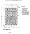
- the single ones Parts of the synthesis block are shown in Figs. 2a - 2e.
- This synthesis block is particularly characterized by that an inert material is used, preferably Delrin, PTFE or ceramic materials.
- the synthesis block shown in Fig. 1 is characterized by a three-part structure, whereby between Part I and Part II a synthesis membrane is arranged.
- Part I contains juxtaposed holes, one Have an inside diameter of approx. 3 mm, with the borehole diameter of course, each for the respective application can be of a suitable size.
- a sealing ring e.g. made of PFTE / silicone, sealed.
- the number of holes is at least 96, preferably 384 or more.
- Part II preferably has the following structure: Below the Part I's x, y holes is a coarse-pore membrane or plate, e.g. made of PE, PP, PFTE or Delrin, from several mm thickness, preferably 2-15 mm, very preferably 4-10 mm, as Support for the preferably functionalized synthetic membrane, that comes between parts I and II.
- the pore size of the coarse-pore membrane is preferably from 100 to 250 microns, preferably 120 to 200 microns.
- Part II boreholes that, as in Part I, have at least 96 is preferably 384 or more, and also with one each Sealing ring, e.g. made of PFTE / silicone. In a 2.
- Part III contains a device in the form of at least one Suction piece in order to apply a vacuum to the apparatus can.
- part III side by side holes preferably in Number and size correspond to those of parts I and II.
- a preferred modification is the presence of a second Vacuum channel in part III, which is to prevent that Collect reagents on the outer edge of the membrane.
- the two Vacuum areas are preferably made of seals Silicon, separated and can be used with different negative pressures operate.
- the equipment is assembled by laying one on top of the other the parts, with locking devices for locking, e.g. in the form of buckles.
- the one between Part I and Part II Synthetic membrane is one that is designed to bind Polymers are suitable and have a pore size of 0.1 to 1.3 ⁇ m, preferably 0.2 to 1.0 ⁇ m.
- a membrane can all common materials in this area and should preferably have functional groups on their surface, such as hydroxyl, amino, amide, phosphate, alkyl, halogen, Carboxyl, carbonyl, thio, aryl groups, ethene groups (e.g. Vinyl, vinyloxy, vinyloxycarbonyl and the corresponding pure thio or mixed thio analogues) or Ethinement wear.
- the basic materials for the membranes are nylon, Polyamide, cellulose, polypropylene, PFTE, polyolefin, polyethylene or polystyrene, polyvinylidene fluoride, glass fiber, PVC, Polymethylpentene, polynorbornene copolymers (e.g. Topas, Fa. Maximum).
- the one used is very preferably Membrane around a membrane made of surface oxidized (hydrophilized) Polypropylene that derivatizes accordingly has been.
- the membrane preferably has compartments that once automatically arise from the fact that the membrane in the Synthesis block is clamped and through the sealing rings on the Bottom of Part I of the Synthesis Block Pinch-Offs arise that a lateral delimitation of the round reaction surfaces cause.
- the reagents to be applied in series especially the activated monomers during production a molecule library, are now added in precisely metered amounts, to avoid lateral contamination.
- the delivered Volume should be such that the resulting stains do not run into each other. All parallel chemical Steps, e.g. Application of the washing solutions takes place in the Excess, i.e. the chemicals are distributed in everyone Reaction chambers, but are created by an applied vacuum sucked down through the pad. Laterally preferably another vacuum is applied to remove excess Aspirate reagent (see Fig. 2e).
- welds can be made on the membrane beforehand Areas are applied that exactly match the holes of parts I and II correspond to and fit into the synthesis block Need to become.
- This formally creates one of the usual synthesis formats identical arrangement with relatively small, mutually delimited membrane surfaces. It works in such a way that the membrane is inserted into the synthesis block becomes.
- an inert thermoplastic e.g. low melting polypropylene granules
- reagents which can be applied serially or in parallel can now also be applied in excess without it becoming a lateral contamination comes because of the membrane compartments are sealed against each other.
- a "fried egg" structure is created, their delimited units an advantage with regard to the avoidance of contamination and Carryover of reactants across the entire membrane.
- Reagents are made using commercially available synthesizers (e.g. Spot synthesizer from Abimed Analysentechnik, Langenfeld, Germany) into the holes of Part I of the synthesis block pipetted the membrane surface and there covalently through a chemical reaction bound. Excess reagents or wash solutions are vacuumed off. This shortens the cycle time significantly, the binding of the polymers to the Membrane surface and thus the structure of a molecule library takes place much faster.
- a screening process e.g. hybridization of a radioactive labeled DNA probe due to specific Base pairing
- This takes place without that the oligomers in other vessels as in the prior art transferred or anchored to other carriers have to. This ensures that, for example entire molecule library under exactly the same conditions specific interactions can be checked.
- DNA DNA, RNA, amino acids, Peptides, proteins, nucleic acid analogues (e.g. PNA, LNA) be understood.
- PNA nucleic acid analogue
- the respective stock solution was warmed up and mixed in a ratio of 1: 1: 1 with 0.3 molar HOAt stock solution and 0.4 molar DIC stock solution. From this mixture, 0.2 ⁇ l per spot was applied to the membrane. This was repeated 3 times, the reaction time after each application was 20-40 min. An 8x12 grid in microtiter plate format was spotted.
- Fmoc-A (aeg) -OH (lines 1, 5, 9); Fmoc-C (aeg) -OH (lines 2, 6, 10); Fmoc-G (aeg) -OH (lines 3, 7, 11) or Fmoc-T (aeg) -OH (lines 4, 8 12).
- the membrane was divided into the 3 arrays, Array 1 and 3 frozen.
- Array 2 was 10 min at RT in 9.5 ml TFA, 500 ul Triisobutylsilane incubated (cleavage of the Side protection groups), 2 x in DMF and 1 x in ethanol and dried.
- array 2 was incubated in hybridization solution (d (T) 16 33 P ⁇ ATP) for 30 'at RT and washed. The membrane was then exposed on a phosphorimager screen overnight. The image shown in FIG. 3a was shown.
- the membrane was then washed and additionally incubated in hybridization solution (d (C) 16 33 P ⁇ ATP) for 30 'at RT, washed and exposed for 4 days on a phosphor imager screen.
- hybridization solution d (C) 16 33 P ⁇ ATP
- the efficiency of the first coupling can be determined from the fluorescence intensity of the first condensed component become.
- Fmoc-Lys (Dansyl) -OH was the first Module used. If this fluorescence label is used during the Synthesis can only be used at certain points via the relative intensity the condensation yield can be determined. At 353 nm (normal UV lamp) this results in FIG. 3c shown image. From this it can be seen that the distribution the spots took place selectively and no cross-contamination he follows.
Landscapes
- Chemical & Material Sciences (AREA)
- Organic Chemistry (AREA)
- Analytical Chemistry (AREA)
- Chemical Kinetics & Catalysis (AREA)
- Health & Medical Sciences (AREA)
- General Health & Medical Sciences (AREA)
- Life Sciences & Earth Sciences (AREA)
- Genetics & Genomics (AREA)
- Engineering & Computer Science (AREA)
- Water Supply & Treatment (AREA)
- Hematology (AREA)
- Biochemistry (AREA)
- Biophysics (AREA)
- Clinical Laboratory Science (AREA)
- Medicinal Chemistry (AREA)
- Molecular Biology (AREA)
- Proteomics, Peptides & Aminoacids (AREA)
- Measuring Or Testing Involving Enzymes Or Micro-Organisms (AREA)
- Separation Using Semi-Permeable Membranes (AREA)
- Solid-Sorbent Or Filter-Aiding Compositions (AREA)
Description
Durchflußeinrichtungen werden bisher nur zu Filtrationszwecken eingesetzt und sind z.B. von der Firma Schleicher & Schüll, 37582 Dassel erhältlich.
- Fig. 1:
- Syntheseblock
- Fig. 2:
- Aufbau des Syntheseblocks
- a: Syntheseblock Teil I Aufischt
- b: Syntheseblock Teil I Unterseite
- c: Syntheseblock Teil I Unterseite, Bohrloch vergrößert
- d: Syntheseblock Teil II Aufsicht
- e: Syntheseblock Teil III Aufsicht
- Fig. 3:
-
- a: Membran hybridisiert mit d(T)16 33PγATP
- b: Membran zusätzlich hybridisiert mit d (C)16 33PγATP
- c: Kontrolle
- Membran:
- hydrophilisiertes Polypropylen, Porengröße 0,2 µm, umgesetzt mit Trisamin-Jeffamin 500 (bisfunktionelles Amino-Polyethylenglykol) nach Carbonyldiimidazol-Aktivierung Beladung: 0,12 µmol/cm2
- Vorbehandlung:
- Membran mit einer Mischung aus 2 ml NMP, 33 µlDiisopropylcarbodiimid (DIC), 62,0 mg Fmoc-β-Ala-OH, 27,0 mg HOAt eingeschweißt und 3 h bei 37°C inkubiert.
- Reaktionszyklus:
-
- Capping in 20 ml DMF + 600 µl Essigsäureanhydrid; 30"
- Capping in 20 ml DMF+600 µl Essigsäureanhydrid; 2'
- 2 x waschen in DMF, 2' und 5'
- 2 x waschen in Ethanol, 2' und 5'
- 2 x waschen in DMF, 2' und 5'
- entschützen in 20% Piperidin in DMF
- 2 x waschen in DMF, 2' und 5'
- 2 x waschen in Ethanol, 2' und 5'
- 2 x waschen in DMF, 2' und 5'
- Färben in 20 ml DMF + 600 µl BPB-Stammlösung, 10 mg/ml
- Entfärben in Ethanol
- trocknen
Gespottet wurde ein 8x12 - Raster im Mikrotiterplattenformat.
- Capping in 20 ml DMF+600 µl Essigsäureanhydrid (+ 600 µl Pyridin); 200 µl pro Spot; 10' Reaktionszeit, absaugen
- 2 x waschen in DMF; 200 µl pro Spot; permanent absaugen
- 2 x waschen in Ethanol; permanent absaugen
- 2 x waschen in DMF; permanent absaugen
- entschützen in 20 % Piperidin in DMF; 10' Reaktionszeit, absaugen
- 2 x waschen in DMF; 200 µl pro Spot; permanent absaugen
- 2 x waschen in Ethanol; permanent absaugen
- mindestens 45' trockensaugen.
- Fmoc-Rink-Handle (in Array 1, Zeilen 1-4) bzw. Fmoc-β-Ala-OH (in Array 2 und 3, Zeilen 5-8 und 9-12)
- Fmoc-Lys(Dansyl)-OH.
Claims (12)
- Durchflußeinrichtung mit mindestens dreiteiligem Aufbau und einer Abfolge der Teile I, II, III, wobeiTeil I nebeneinander angeordnete Bohrlöcher enthält, die an ihrer Unterseite jeweils durch einen Dichtring abgedichtet sind,Teil II eine grobporige Membran; in einer 1. Vertiefung nebeneinander angeordnete Bohrlöcher, die jeweils durch einen Dichtring abgedichtet sind; und in einer 2. Vertiefung einen Saugkanal zum Anlegen eines Vakuums enthält,Teil III in einer 1. Vertiefung nebeneinander angeordnete Bohrlöcher, die jeweils durch einen Dichtring abgedichtet sind, und mindestens einen Anschluß zum Anlegen eines Vakuums enthält.
- Durchflußeinrichtung nach Anspruch 1, wobei sich zwischen Teil I und Teil II eine Synthesemembran, die zur Bindung von Biopolymeren befähigt ist, befindet.
- Durchflußeinrichtung nach Anspruch 2, wobei die Synthesemembran funktionalisiert ist.
- Durchflußeinrichtung nach Anspruch 2 oder 3, wobei die Synthesemembran aus Nylon, Polyamid, Cellulose, Polypropylen, PFTE, Polyolefin, Polyethylen oder Polystyrol, Polyvinylidenfluorid, Glasfiber, PVC, Polymethylpenten oder Polynorbornen-Copolymere ist.
- Durchflußeinrichtung nach Anspruch 3 oder 4, wobei die Synthesemembran Hydroxyl-, Amino-, Amid-, Phosphat-, Alkyl-, Halogen-, Carboxyl-, Carbonyl-, Thio-, Arylgruppen, Ethengruppen oder Ethingruppen aufweist.
- Durchflußeinrichtung nach einem der vorhergehenden Ansprüche, wobei Teil III zwei Anschlüsse zum Anlegen von Vakuum aufweist.
- Durchflußeinrichtung nach einem der vorhergehenden Ansprüche, wobei die grobporige Membran in Teil II aus Polyethylen, Polypropylen, PFTE oder Delrin besteht.
- Durchflußeinrichtung nach einem der vorhergehenden Ansprüche, wobei die Durchflußeinrichtung aus einem inerten Material aufgebaut ist.
- Durchflußeinrichtung nach Anspruch 8, wobei das inerte Material Delrin, PTFE oder keramisches Material ist.
- Verwendung der Durchflußeinrichtung nach einem der vorhergehenden Ansprüche zum Binden von Biopolymeren an Membranoberflächen.
- Verwendung nach Anspruch 10, wobei es sich um den Aufbau von membrangebundenen Molekülbibliotheken handelt.
- Verwendung nach Anspruch 10 oder 11, wobei die Biopolymeren bzw. Molekülbibliotheken DNA, RNA, Aminosäuren, Peptide, Proteinen, Nukleinsäureanaloga umfassen.
Applications Claiming Priority (3)
| Application Number | Priority Date | Filing Date | Title |
|---|---|---|---|
| DE19904784 | 1999-02-05 | ||
| DE19904784A DE19904784A1 (de) | 1999-02-05 | 1999-02-05 | Durchflußeinrichtung sowie ihre Verwendung zum Binden von Polymeren an Membranoberflächen |
| PCT/DE2000/000365 WO2000045950A1 (de) | 1999-02-05 | 2000-02-04 | Durchflusseinrichtung sowie ihre verwendung zum binden von polymeren an membranoberflächen |
Publications (2)
| Publication Number | Publication Date |
|---|---|
| EP1148942A1 EP1148942A1 (de) | 2001-10-31 |
| EP1148942B1 true EP1148942B1 (de) | 2002-10-23 |
Family
ID=7896594
Family Applications (1)
| Application Number | Title | Priority Date | Filing Date |
|---|---|---|---|
| EP00909002A Expired - Lifetime EP1148942B1 (de) | 1999-02-05 | 2000-02-04 | Durchflusseinrichtung sowie ihre verwendung zum binden von polymeren an membranoberflächen |
Country Status (4)
| Country | Link |
|---|---|
| EP (1) | EP1148942B1 (de) |
| AT (1) | ATE226478T1 (de) |
| DE (2) | DE19904784A1 (de) |
| WO (1) | WO2000045950A1 (de) |
Cited By (2)
| Publication number | Priority date | Publication date | Assignee | Title |
|---|---|---|---|---|
| US8007744B2 (en) | 2003-01-17 | 2011-08-30 | Greiner Bio-One Gmbh | Sample container for analyses |
| US9005549B2 (en) | 2003-01-17 | 2015-04-14 | Greiner Bio-One Gmbh | High throughput polymer-based microarray slide |
Families Citing this family (9)
| Publication number | Priority date | Publication date | Assignee | Title |
|---|---|---|---|---|
| WO2001019502A2 (en) * | 1999-09-17 | 2001-03-22 | Millipore Corporation | High throughput screening card |
| US7390463B2 (en) | 2001-09-07 | 2008-06-24 | Corning Incorporated | Microcolumn-based, high-throughput microfluidic device |
| JP3836379B2 (ja) * | 2002-02-01 | 2006-10-25 | 富士写真フイルム株式会社 | リセプター・リガンド会合反応方法 |
| JP3818926B2 (ja) * | 2002-02-04 | 2006-09-06 | 富士写真フイルム株式会社 | リセプター・リガンド会合反応方法 |
| JP3883934B2 (ja) * | 2002-08-29 | 2007-02-21 | 富士フイルムホールディングス株式会社 | 生化学解析用ユニットを利用した化学発光法 |
| DE10321042B4 (de) * | 2003-01-17 | 2006-09-21 | Greiner Bio-One Gmbh | Biochip-Träger |
| JP2006038460A (ja) * | 2004-07-22 | 2006-02-09 | Olympus Corp | 基板固定装置及びこれを備えた試験片の製造装置並びに試験片の製造方法 |
| US20060046269A1 (en) * | 2004-09-02 | 2006-03-02 | Thompson Allen C | Methods and devices for processing chemical arrays |
| JP2008145365A (ja) * | 2006-12-13 | 2008-06-26 | Sysmex Corp | タンパク固相用チップ、タンパク固相形成装置並びにタンパク発現量及び活性値測定装置 |
Family Cites Families (10)
| Publication number | Priority date | Publication date | Assignee | Title |
|---|---|---|---|---|
| US4493815A (en) * | 1983-07-28 | 1985-01-15 | Bio-Rad Laboratories, Inc. | Supporting and filtering biochemical test plate assembly |
| IT1206777B (it) * | 1987-04-06 | 1989-05-03 | Chemetron Del Dr Del Campo Gio | Procedimento di analisi immunologica o chimica per la determinazione di proteine in fluidi biologici e relativo completo (kit) di mezzi analitici. |
| US5141719A (en) * | 1990-07-18 | 1992-08-25 | Bio-Rad Laboratories, Inc. | Multi-sample filtration plate assembly |
| US5108603A (en) * | 1991-04-04 | 1992-04-28 | Life Technologies, Inc. | Self-contained vacuum clamped multi-sample media filtration apparatus and method |
| DK0631634T3 (da) * | 1992-03-20 | 1996-06-24 | Celsis Int Plc | Fremgangsmåde og apparat til analyse af biologisk materiale |
| US5585275A (en) * | 1992-09-02 | 1996-12-17 | Arris Pharmaceutical Corporation | Pilot apparatus for peptide synthesis and screening |
| US5792430A (en) * | 1996-08-12 | 1998-08-11 | Monsanto Company | Solid phase organic synthesis device with pressure-regulated manifold |
| JP2001511794A (ja) * | 1997-02-17 | 2001-08-14 | ゲゼルシャフト・フュア・ビオテヒノロジッシェ・フォルシュング・エムベーハー(ゲー・ベー・エフ) | 自動化学合成装置 |
| DE19725894A1 (de) * | 1997-06-19 | 1998-12-24 | Biotechnolog Forschung Gmbh | Differentielle Vakuumkammer |
| US6083682A (en) * | 1997-12-19 | 2000-07-04 | Glaxo Group Limited | System and method for solid-phase parallel synthesis of a combinatorial collection of compounds |
-
1999
- 1999-02-05 DE DE19904784A patent/DE19904784A1/de not_active Ceased
-
2000
- 2000-02-04 EP EP00909002A patent/EP1148942B1/de not_active Expired - Lifetime
- 2000-02-04 DE DE50000673T patent/DE50000673D1/de not_active Expired - Fee Related
- 2000-02-04 AT AT00909002T patent/ATE226478T1/de not_active IP Right Cessation
- 2000-02-04 WO PCT/DE2000/000365 patent/WO2000045950A1/de not_active Ceased
Cited By (2)
| Publication number | Priority date | Publication date | Assignee | Title |
|---|---|---|---|---|
| US8007744B2 (en) | 2003-01-17 | 2011-08-30 | Greiner Bio-One Gmbh | Sample container for analyses |
| US9005549B2 (en) | 2003-01-17 | 2015-04-14 | Greiner Bio-One Gmbh | High throughput polymer-based microarray slide |
Also Published As
| Publication number | Publication date |
|---|---|
| DE50000673D1 (de) | 2002-11-28 |
| ATE226478T1 (de) | 2002-11-15 |
| DE19904784A1 (de) | 2000-08-10 |
| WO2000045950A1 (de) | 2000-08-10 |
| EP1148942A1 (de) | 2001-10-31 |
Similar Documents
| Publication | Publication Date | Title |
|---|---|---|
| DE69233331T3 (de) | Kombinatorische Strategien zur Polymersynthese | |
| DE69824586T2 (de) | Probenträger hoher dichte für die analyse biologischer proben | |
| DE69703841T2 (de) | Elektrochemischer festphasensynthese von polymere | |
| DE19740263C2 (de) | Kachelungsverfahren zum Bauen eines chemischen Arrays | |
| DE60031506T2 (de) | Fasermatrix zum zusammenbringen von chemischen stoffen, sowie verfahren zur herstellung und anwendung davon | |
| DE69812154T2 (de) | Vorrichtung und verfahren zur trennung von flüssigen und festen phasen in organischen festphasensynthesen | |
| DE69334108T2 (de) | Elektrisches Verfahren zur Bestimmung von Molekülen | |
| DE69926260T2 (de) | Kompositmatrix mit mikrokugeln | |
| DE60111310T2 (de) | Verfahren, Vorrichtung und Rechnerprogramm zur Herstellung eines Arrays chemischer Vebindungen | |
| DE69425673T2 (de) | Gerät und verfahren zur polymersynthese mit gerüsten | |
| DE19854946C2 (de) | Klonieren und Kopieren an Oberflächen | |
| AU7599698A (en) | Color-encoding and in-situ interrogation of matrix-coupled chemical compounds | |
| WO2000013018B1 (de) | Träger für analytbestimmungsverfahren und verfahren zur herstellung des trägers | |
| DE19904784A1 (de) | Durchflußeinrichtung sowie ihre Verwendung zum Binden von Polymeren an Membranoberflächen | |
| EP1436609B1 (de) | Mikrofluidisches extraktionsverfahren | |
| DE10308931A1 (de) | System und Verfahren zur Synthese von Polymeren | |
| EP1165227A1 (de) | Mikrosäulenreaktor | |
| DE10040857A1 (de) | Nukleinsäurenbibliothek oder Protein- oder Peptidbibliothek | |
| WO2001072412A1 (de) | Verfahren und vorrichtung zum aufbau und untersuchung von substanzbibliotheken | |
| DE3788169T2 (de) | Geräte und Verfahren zur Bestimmung der Sequenz von Aminosäuren. | |
| EP1441847A1 (de) | Träger zur synthese sowie verfahren zur herstellung von biopolymeren | |
| WO2017064165A1 (de) | Ultra-hochdichte oligomerarrays und verfahren zu deren herstellung | |
| EP1361920B1 (de) | Synthesevorrichtung und verfahren zu deren herstellung | |
| DE102004023906A1 (de) | Verfahren zur Herstellung von chemischen Mikroarrays | |
| EP1649045A2 (de) | Einbau von hapten-gruppen bei der herstellung von trägern für die analytbestimmung |
Legal Events
| Date | Code | Title | Description |
|---|---|---|---|
| PUAI | Public reference made under article 153(3) epc to a published international application that has entered the european phase |
Free format text: ORIGINAL CODE: 0009012 |
|
| 17P | Request for examination filed |
Effective date: 20010808 |
|
| AK | Designated contracting states |
Kind code of ref document: A1 Designated state(s): AT BE CH CY DE DK ES FI FR GB GR IE IT LI LU MC NL PT SE |
|
| GRAG | Despatch of communication of intention to grant |
Free format text: ORIGINAL CODE: EPIDOS AGRA |
|
| 17Q | First examination report despatched |
Effective date: 20011203 |
|
| GRAG | Despatch of communication of intention to grant |
Free format text: ORIGINAL CODE: EPIDOS AGRA |
|
| GRAH | Despatch of communication of intention to grant a patent |
Free format text: ORIGINAL CODE: EPIDOS IGRA |
|
| GRAH | Despatch of communication of intention to grant a patent |
Free format text: ORIGINAL CODE: EPIDOS IGRA |
|
| GRAA | (expected) grant |
Free format text: ORIGINAL CODE: 0009210 |
|
| AK | Designated contracting states |
Kind code of ref document: B1 Designated state(s): AT BE CH CY DE DK ES FI FR GB GR IE IT LI LU MC NL PT SE |
|
| PG25 | Lapsed in a contracting state [announced via postgrant information from national office to epo] |
Ref country code: NL Free format text: LAPSE BECAUSE OF FAILURE TO SUBMIT A TRANSLATION OF THE DESCRIPTION OR TO PAY THE FEE WITHIN THE PRESCRIBED TIME-LIMIT Effective date: 20021023 Ref country code: GR Free format text: LAPSE BECAUSE OF FAILURE TO SUBMIT A TRANSLATION OF THE DESCRIPTION OR TO PAY THE FEE WITHIN THE PRESCRIBED TIME-LIMIT Effective date: 20021023 Ref country code: FI Free format text: LAPSE BECAUSE OF FAILURE TO SUBMIT A TRANSLATION OF THE DESCRIPTION OR TO PAY THE FEE WITHIN THE PRESCRIBED TIME-LIMIT Effective date: 20021023 |
|
| REF | Corresponds to: |
Ref document number: 226478 Country of ref document: AT Date of ref document: 20021115 Kind code of ref document: T |
|
| REG | Reference to a national code |
Ref country code: GB Ref legal event code: FG4D Free format text: NOT ENGLISH |
|
| REG | Reference to a national code |
Ref country code: CH Ref legal event code: EP |
|
| REG | Reference to a national code |
Ref country code: IE Ref legal event code: FG4D Free format text: GERMAN |
|
| REF | Corresponds to: |
Ref document number: 50000673 Country of ref document: DE Date of ref document: 20021128 |
|
| PG25 | Lapsed in a contracting state [announced via postgrant information from national office to epo] |
Ref country code: PT Free format text: LAPSE BECAUSE OF FAILURE TO SUBMIT A TRANSLATION OF THE DESCRIPTION OR TO PAY THE FEE WITHIN THE PRESCRIBED TIME-LIMIT Effective date: 20030123 Ref country code: DK Free format text: LAPSE BECAUSE OF FAILURE TO SUBMIT A TRANSLATION OF THE DESCRIPTION OR TO PAY THE FEE WITHIN THE PRESCRIBED TIME-LIMIT Effective date: 20030123 |
|
| PG25 | Lapsed in a contracting state [announced via postgrant information from national office to epo] |
Ref country code: LU Free format text: LAPSE BECAUSE OF NON-PAYMENT OF DUE FEES Effective date: 20030204 Ref country code: CY Free format text: LAPSE BECAUSE OF FAILURE TO SUBMIT A TRANSLATION OF THE DESCRIPTION OR TO PAY THE FEE WITHIN THE PRESCRIBED TIME-LIMIT Effective date: 20030204 |
|
| PG25 | Lapsed in a contracting state [announced via postgrant information from national office to epo] |
Ref country code: MC Free format text: LAPSE BECAUSE OF NON-PAYMENT OF DUE FEES Effective date: 20030228 |
|
| GBT | Gb: translation of ep patent filed (gb section 77(6)(a)/1977) |
Effective date: 20030220 |
|
| NLV1 | Nl: lapsed or annulled due to failure to fulfill the requirements of art. 29p and 29m of the patents act | ||
| REG | Reference to a national code |
Ref country code: CH Ref legal event code: NV Representative=s name: A. BRAUN, BRAUN, HERITIER, ESCHMANN AG PATENTANWAE |
|
| PG25 | Lapsed in a contracting state [announced via postgrant information from national office to epo] |
Ref country code: ES Free format text: LAPSE BECAUSE OF FAILURE TO SUBMIT A TRANSLATION OF THE DESCRIPTION OR TO PAY THE FEE WITHIN THE PRESCRIBED TIME-LIMIT Effective date: 20030429 |
|
| ET | Fr: translation filed | ||
| PLBE | No opposition filed within time limit |
Free format text: ORIGINAL CODE: 0009261 |
|
| STAA | Information on the status of an ep patent application or granted ep patent |
Free format text: STATUS: NO OPPOSITION FILED WITHIN TIME LIMIT |
|
| 26N | No opposition filed |
Effective date: 20030724 |
|
| PGFP | Annual fee paid to national office [announced via postgrant information from national office to epo] |
Ref country code: SE Payment date: 20040223 Year of fee payment: 5 Ref country code: FR Payment date: 20040223 Year of fee payment: 5 |
|
| PGFP | Annual fee paid to national office [announced via postgrant information from national office to epo] |
Ref country code: AT Payment date: 20040224 Year of fee payment: 5 |
|
| PGFP | Annual fee paid to national office [announced via postgrant information from national office to epo] |
Ref country code: GB Payment date: 20040226 Year of fee payment: 5 |
|
| PGFP | Annual fee paid to national office [announced via postgrant information from national office to epo] |
Ref country code: BE Payment date: 20040301 Year of fee payment: 5 |
|
| PGFP | Annual fee paid to national office [announced via postgrant information from national office to epo] |
Ref country code: CH Payment date: 20040302 Year of fee payment: 5 |
|
| PGFP | Annual fee paid to national office [announced via postgrant information from national office to epo] |
Ref country code: IE Payment date: 20040304 Year of fee payment: 5 |
|
| PGFP | Annual fee paid to national office [announced via postgrant information from national office to epo] |
Ref country code: DE Payment date: 20040430 Year of fee payment: 5 |
|
| PG25 | Lapsed in a contracting state [announced via postgrant information from national office to epo] |
Ref country code: IT Free format text: LAPSE BECAUSE OF NON-PAYMENT OF DUE FEES Effective date: 20050204 Ref country code: IE Free format text: LAPSE BECAUSE OF NON-PAYMENT OF DUE FEES Effective date: 20050204 Ref country code: AT Free format text: LAPSE BECAUSE OF NON-PAYMENT OF DUE FEES Effective date: 20050204 |
|
| PG25 | Lapsed in a contracting state [announced via postgrant information from national office to epo] |
Ref country code: SE Free format text: LAPSE BECAUSE OF NON-PAYMENT OF DUE FEES Effective date: 20050205 |
|
| PG25 | Lapsed in a contracting state [announced via postgrant information from national office to epo] |
Ref country code: LI Free format text: LAPSE BECAUSE OF NON-PAYMENT OF DUE FEES Effective date: 20050228 Ref country code: CH Free format text: LAPSE BECAUSE OF NON-PAYMENT OF DUE FEES Effective date: 20050228 Ref country code: BE Free format text: LAPSE BECAUSE OF NON-PAYMENT OF DUE FEES Effective date: 20050228 |
|
| BERE | Be: lapsed |
Owner name: DEUTSCHES *KREBSFORSCHUNGSZENTRUM STIFTUNG DES OFF Effective date: 20050228 |
|
| PG25 | Lapsed in a contracting state [announced via postgrant information from national office to epo] |
Ref country code: DE Free format text: LAPSE BECAUSE OF NON-PAYMENT OF DUE FEES Effective date: 20050901 |
|
| GBPC | Gb: european patent ceased through non-payment of renewal fee |
Effective date: 20050204 |
|
| EUG | Se: european patent has lapsed | ||
| REG | Reference to a national code |
Ref country code: CH Ref legal event code: PL |
|
| PG25 | Lapsed in a contracting state [announced via postgrant information from national office to epo] |
Ref country code: FR Free format text: LAPSE BECAUSE OF NON-PAYMENT OF DUE FEES Effective date: 20051031 |
|
| REG | Reference to a national code |
Ref country code: IE Ref legal event code: MM4A |
|
| REG | Reference to a national code |
Ref country code: FR Ref legal event code: ST Effective date: 20051031 |
|
| BERE | Be: lapsed |
Owner name: DEUTSCHES *KREBSFORSCHUNGSZENTRUM STIFTUNG DES OFF Effective date: 20050228 |