EP1148205B1 - End cap for roller shutter box - Google Patents
End cap for roller shutter box Download PDFInfo
- Publication number
- EP1148205B1 EP1148205B1 EP01460024A EP01460024A EP1148205B1 EP 1148205 B1 EP1148205 B1 EP 1148205B1 EP 01460024 A EP01460024 A EP 01460024A EP 01460024 A EP01460024 A EP 01460024A EP 1148205 B1 EP1148205 B1 EP 1148205B1
- Authority
- EP
- European Patent Office
- Prior art keywords
- sleeve
- compartment
- housing
- closure device
- cheek
- Prior art date
- Legal status (The legal status is an assumption and is not a legal conclusion. Google has not performed a legal analysis and makes no representation as to the accuracy of the status listed.)
- Expired - Lifetime
Links
- 238000000605 extraction Methods 0.000 claims description 5
- 230000007246 mechanism Effects 0.000 description 44
- 238000005096 rolling process Methods 0.000 description 20
- 239000000470 constituent Substances 0.000 description 6
- 238000004873 anchoring Methods 0.000 description 4
- 238000004804 winding Methods 0.000 description 4
- 241000226585 Antennaria plantaginifolia Species 0.000 description 3
- 230000000694 effects Effects 0.000 description 3
- 238000009434 installation Methods 0.000 description 3
- 238000000034 method Methods 0.000 description 3
- 230000004308 accommodation Effects 0.000 description 2
- 230000000903 blocking effect Effects 0.000 description 2
- 238000010276 construction Methods 0.000 description 2
- 210000002414 leg Anatomy 0.000 description 2
- BASFCYQUMIYNBI-UHFFFAOYSA-N platinum Chemical compound [Pt] BASFCYQUMIYNBI-UHFFFAOYSA-N 0.000 description 2
- 239000004793 Polystyrene Substances 0.000 description 1
- 230000004888 barrier function Effects 0.000 description 1
- 239000011230 binding agent Substances 0.000 description 1
- 238000005266 casting Methods 0.000 description 1
- 239000004568 cement Substances 0.000 description 1
- 238000000576 coating method Methods 0.000 description 1
- 238000011065 in-situ storage Methods 0.000 description 1
- 238000009413 insulation Methods 0.000 description 1
- 230000010354 integration Effects 0.000 description 1
- 210000003127 knee Anatomy 0.000 description 1
- 229910052751 metal Inorganic materials 0.000 description 1
- 239000002184 metal Substances 0.000 description 1
- 238000010422 painting Methods 0.000 description 1
- 210000004417 patella Anatomy 0.000 description 1
- 239000011505 plaster Substances 0.000 description 1
- 239000004033 plastic Substances 0.000 description 1
- 229910052697 platinum Inorganic materials 0.000 description 1
- 229920002223 polystyrene Polymers 0.000 description 1
- 230000001737 promoting effect Effects 0.000 description 1
- 230000000284 resting effect Effects 0.000 description 1
- 230000035939 shock Effects 0.000 description 1
- 238000009416 shuttering Methods 0.000 description 1
Images


Classifications
-
- E—FIXED CONSTRUCTIONS
- E06—DOORS, WINDOWS, SHUTTERS, OR ROLLER BLINDS IN GENERAL; LADDERS
- E06B—FIXED OR MOVABLE CLOSURES FOR OPENINGS IN BUILDINGS, VEHICLES, FENCES OR LIKE ENCLOSURES IN GENERAL, e.g. DOORS, WINDOWS, BLINDS, GATES
- E06B9/00—Screening or protective devices for wall or similar openings, with or without operating or securing mechanisms; Closures of similar construction
- E06B9/02—Shutters, movable grilles, or other safety closing devices, e.g. against burglary
- E06B9/08—Roll-type closures
- E06B9/11—Roller shutters
- E06B9/17—Parts or details of roller shutters, e.g. suspension devices, shutter boxes, wicket doors, ventilation openings
-
- E—FIXED CONSTRUCTIONS
- E06—DOORS, WINDOWS, SHUTTERS, OR ROLLER BLINDS IN GENERAL; LADDERS
- E06B—FIXED OR MOVABLE CLOSURES FOR OPENINGS IN BUILDINGS, VEHICLES, FENCES OR LIKE ENCLOSURES IN GENERAL, e.g. DOORS, WINDOWS, BLINDS, GATES
- E06B9/00—Screening or protective devices for wall or similar openings, with or without operating or securing mechanisms; Closures of similar construction
- E06B9/24—Screens or other constructions affording protection against light, especially against sunshine; Similar screens for privacy or appearance; Slat blinds
- E06B9/40—Roller blinds
- E06B2009/407—Telescopic roller
Definitions
- the present invention relates to a shutter device made of preferably plastic and intended to close each of the two ends sides of a rolling shutter tunnel tunnel.
- tunnel boxes are designed to be integrated during construction in the masonry of a building above window openings or door, as shown in Fig. 1.
- Each tunnel safe generally consists of a molded shell having a tunnel-shaped recess with the lower part open to accommodate a roller shutter.
- Each obturator consisting mainly of a cheek and a heel perpendicular to it, is designed to receive a rolling shutter composed of an axis roller shutter, apron and runners.
- a roller shutter axis is a cylindrical or octagonal metal tube on which can hang on the deck. This tube is equipped with each of its ends of a nozzle inserted by force.
- a tip shaft mounted free to rotate in said endpiece is fixed to the cheek by means of a support accessory shaft. According to another technique from the accessory manufacturer, the shaft end can be fitted on a pivot fixed on the shaft support accessory called support pivot.
- roller shutter axis At one end of the roller shutter axis, between the end piece and the support shaft, takes place a manual operating mechanism of the pulley type with strap or crank winch.
- the latter can be compensated to facilitate its use depending on the surface or weight of the deck. Compensation is carried out on the tip shaft opposite to the operating mechanism.
- the motor assembly When the roller shutter axis is motorized by an operating mechanism motorized, the motor assembly includes the nozzle.
- the shaft support accessory is then specific on the engine side and called the engine support.
- the tip is generally telescopic so that the total length of the flap axis can be varied rolling equipped when introduced into the recess of the tunnel box, the opening is reduced by the presence of the heels.
- the inner faces of the cheeks include reservations provided to allow screw fixing of the shaft support accessories, pivot supports, engine supports or to immobilize the winch in the desired angle of connection to a knee lifter equipped with its crank (90 ° or 75 °).
- the operating mechanism allows to rotate the roller shutter axis as described and on which is fixed the roller shutter deck. So to close the doorway the apron unrolls around the roller shutter axis on descent by sliding in U-shaped profiles, commonly known as backstage.
- the shaft support accessory which in the example chosen below, is a pin bearing.
- This pin cushion has a finger positioned parallel to the cheek and the free end of which must point towards the roof of the tunnel safe. This finger is intended to allow the attachment of one end of the endpiece shaft by a drilled hole radially in it.
- the non-telescopic end of the support shaft is mounted through the operating mechanism then is hooked to the pin cushion of a cheek.
- the operating mechanism is then properly oriented and then fixed with screws against the inner wall of said cheek.
- a pin is then fitted into the pin pad to prevent that said end does not come off during the operation of the shutter.
- a pin is also fitted into this pin cushion for avoid the subsequent detachment of said telescopic end.
- the manufacturers of fasteners are promoting tunnel-safe delivered to site already equipped with its rolling shutter fitted in the workshop.
- the tunnel safe can be placed at the right height, turned upside down, i.e. with its recess exposed upwards to facilitate the positioning and fixing of the components of the roller shutter.
- the installation of the rolling shutter on site in a tunnel-safe already integrated into the masonry remains the most suitable solution when the apron is "internal winding", that is to say that the slides are placed on the masonry of tables and that the slats of the apron are facing in the normal direction.
- the planned width of the deck is only final when the coatings of the paintings are finished.
- the mechanism consists of a cheek mounted in one end of a cabinet.
- the end of the shaft which is intended to be driven is mounted, by means of an axis in a bearing which is housed in a protrusion of the cheek.
- the object of the invention is therefore to propose a shutter device for rolling shutter tunnel for in-situ mounting of the components of the roller shutter in the tunnel box that is as easy and quick as mounting in workshop and that removes the guesswork and the risk of wrong mistakes positioning of its constituents.
- Another object of the invention is to propose a shutter device for rolling shutter tunnel for universal mounting that can adapt to all types of roller shutters.
- the shutter device intended to close a lateral end of a rolling shutter tunnel said shutter being constituted in particular of a cheek associated with a heel, is remarkable in that the cheek has a housing formed in protrusion of the outer face of the cheek and intended to receive internally a sleeve comprising a housing of polygonal section for accommodating a shaped end of a rolling shutter end shaft or an insert pin or an engine mount.
- the housing is cylindrical and comprises at least one notch which is formed longitudinally and in relief on the internal wall of said cylindrical housing, said notching making it possible to overlap respectively a notch formed on the envelope of the sleeve to allow the positioning in rotation of said sleeve in the cylindrical housing.
- the housing comprises a groove adjoining the bottom of the housing for housing a step formed on a lug disposed at the end of an elastic finger formed in a cut made in a notch in the sleeve casing so as to block the sleeve in translation in the cylindrical housing.
- the sleeve has a point anchor formed on the lug allowing a tool having passed through an opening made through a shoulder of said sleeve to deform the elastic finger by acting on said anchor point to bring out the step of the gorge and allow extracting the sleeve from the housing.
- the shutter device, the cheek has a plate is remarkable in that a conduit is made in the platinum, said duct opening, on the one hand, into the internal face of the cheek and, on the other hand part, inside the housing to allow the introduction of a tool in the housing to act on the anchoring point.
- the sleeve comprises a lug provided with a step formed on an elastic finger formed in a cut made in through one side of the housing of polygonal section allowing said step to be lodge in an orifice or in a groove made respectively in the end shaped or in the insert, so as to lock the shaft respectively axially tip or insert in the polygonal section of the sleeve, by clipping.
- the sleeve has a point anchor formed at the free end of the elastic finger allowing a tool having crossed an opening made through the shoulder to deform the finger elastic to bring out the lug of the hole to allow the extraction of the shaft tip or sleeve insert.
- the sectional housing polygonal has a square section.
- the sectional housing polygonal is a concave polygon with a concave polygonal section of shape quatrefoil.
- the tunnel safe 400 shown in FIG. 1 is intended to be integrated into the masonry M above the doorway of a window or door of a building. he is in particular embedded in the masonry M by its two lateral ends 402 and 404 and through the vault V.
- the shutter device D shown in FIG. 2 is globally constituted a cheek 100, a heel 300 and an anchor 200.
- the shutter device D is intended to be mounted laterally in each ends 402 or 404 of a tunnel safe 400 so as to close so airtight from the internal recess of the tunnel safe, said end side 402 or 404 of said tunnel safe 400.
- the tunnel safe 400 is represented by honeycomb cells with Figs. 2, 6, 7 and 8.
- the tunnel safe 400 consists of a shell based on polystyrene delimited in length by two lateral ends 402 and 404. A only lateral end 402 is visible in this FIG.
- the cheek 100 of the shutter device D comprises a plate 120 on which is disposed perpendicularly a support edge 110.
- the support edge 110 is provided to closely match the walls internal of the vault V and the J1 and J2 legs of the tunnel safe, so as to ensure the precise positioning of the cheek 100 relative to a lateral end 402 or 404 of the tunnel safe 400. In FIG. 2, only the J2 leg is visible in this view in chopped off.
- the plate 120 is extended at its periphery in the same plane by a flange 126 perpendicular to the support edge 110.
- the flange 126 is intended to come into contact with a lateral end 402 or 404 of a tunnel safe 400 to serve as an axial stop for the shutter device D during assembly. Therefore, it is also able to form a barrier airtight between the internal recess of the tunnel safe 400 and a insulation lining inside the building.
- a heel 300 is connected in the lower part of the plate 120 of a cheek 100 perpendicular to said cheek 100 to form a shutter device D piece.
- the heel 300 is intended to support the mass of the rolling shutter attached to the plate 120 of the cheek 100 by resting on the seat of the masonry M provided at this effect.
- the heel 300 also makes it possible to support the tunnel safe 400 during its integration into masonry M.
- An anchor 200 can be inserted in the part of the support edge 110 intended to come into contact with the roof V of a tunnel safe 400, so as to mechanically link the cheek 100 with the arch V of the tunnel safe 400, after the shutter device D has been mounted in a lateral end 402 or 404 of said tunnel safe 400.
- the plate 120 has in its central part a housing 130 formed in protrusion of the external face of the plate 120.
- the housing 130 has a concave polygonal section of quadrilobe shape.
- This housing 130 is intended to receive a sleeve 140 which can accommodate a first shaped end 182 of a tip shaft 180 of a roller shutter.
- the first shaped end 182 has a square section.
- the housing 130 includes notches 132 also visible at Fig. 7 which are formed longitudinally and in relief on the internal wall of said housing 130. These notches 132 are distributed regularly over said internal wall.
- notches 132 are delimited, on the one hand, by a crown 134 produced at the entrance to the housing 130 and, on the other hand, by a groove 136 adjoining the bottom 138 of the housing 130.
- An inlet chamfer 139 is also produced on the notches 132 to the entrance to housing 130.
- the sleeve 140 consists of an envelope 142 of preferably a cylindrical section that can be accommodated in the housing 130 described in Fig. 3.
- a shoulder 144 is formed at one end of the casing 142 and can be housed in the crown 134 of the housing 130 to serve as axial stop when mounting the sleeve 140 in the housing 130.
- Notches 146 are formed longitudinally in hollow on the envelope 142 and are distributed regularly over said envelope 142. These notches 146 are intended to overlap the notches 132 respectively so as to allow a rotation blocking of the sleeve 140 in the housing 130.
- a chamfer 148 is produced on the other end of the casing 142 in order to facilitate the mounting of the sleeve 140 in the housing 130.
- a housing of polygonal section 150 crosses longitudinally the sleeve 140 and admits the housing of the first end 182 of the end-piece shaft 180.
- the section housing polygonal 150 has a square section for accommodating one as shown in Fig. 10.
- the housing of polygonal section 150 has polygonal section concave of quadrilobe shape allowing to house an end 182 shaped with a tip shaft 180, as shown in Figs. 2, 5 and 14.
- a first elastic finger 152 is formed in a cutout produced through one side 154 of the housing of polygonal section 150. This first elastic finger 152 is partially and laterally detached from the cutout made through a side 154 to obtain an elasticity of its walls which go function as a clip.
- the first elastic finger 152 comprises in FIG. 5 a lug 156 provided with a step 158 which emerges naturally from said side 154.
- This step 158 can then, at the end of the housing of the first end conformed 182 of the end-piece shaft 180 in the housing of polygonal section 150, be housed in an orifice 184 formed in said shaped end 182, so to axially lock the tip shaft 180 in the housing of polygonal section 150 of the sleeve 140, by clipping.
- a first opening 160 made through the shoulder 144 allows the passage of a tool, for example the end of a screwdriver not shown, so that it can act by bracing on an anchoring point 162, constituted for example at the Fig. 5 of an orifice 162, formed at the free end of the first elastic finger 152.
- the tool can deform said elastic finger 152 in order to bring out the step 158 of port 184 to allow extraction of the first end 182 of the end-piece shaft 180 of the housing of polygonal section 150.
- a second elastic finger 164 is formed in a cutout produced in a notch 146 of the envelope 142 of the sleeve 140.
- This second elastic finger 164 comprises in FIG. 5 a lug 166 provided with a step 168.
- This step 168 can then, at the end of the housing of the sleeve 140 in the housing 130, be housed in the groove 136 so as to block in translation the sleeve 140 in housing 130.
- a second opening 170 made through the shoulder 144 allows the passage of a tool, for example the end of a screwdriver not shown, so that it can act by bracing on an anchor point 172, constituted for example at the Fig. 5 of a bearing face 172, produced at the free end of the second elastic finger 164.
- the tool can deform the second elastic finger 164 and make pull out the step 168 from the groove 136 to allow the extraction of the sleeve 140 from the housing 130.
- a variant of access to the anchoring point 172 consisting of a duct 170a, is produced in the plate 120 of the cheek 100 at the Fig. 7.
- This conduit 170a opens, on the one hand, into the internal face of the cheek 100 in its lower part and, on the other hand, inside the housing 130.
- This conduit 170a has the particularity of not crossing the cheek 100, which makes it possible to keep watertight the cheek 100 when casting a binder against the external face of said cheek 100 for the join to the masonry of a building.
- a first example of how to assemble a rolling shutter in a tunnel-vault according to the invention is described below with the constituents of a first accessories manufacturer A.
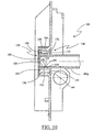
- An operating mechanism 190 constituted in FIG. 6 of a crank winch is assembled against the inner face of the cheek 100.
- This operating mechanism 190 comprises a dog clutch 192 provided central accommodation 194.
- the dog clutch 192 is designed to be housed in a nozzle mounted on the roller shutter axis to allow the rotational drive of said shutter axis roller around which the roller shutter curtain is wound.
- the roller shutter axis and the apron are not shown.
- the central housing 194 can be crossed by the endpiece shaft 180 during the housing the first shaped end 182 of the tip shaft 180 in the housing of polygonal section 150 to allow centering of the mechanism maneuver 190 with respect to the internal face of the cheek 100, as appears in the Fig. 2.
- the operating mechanism 190 also includes a means fixing 196 such as one or more screws 196 in this Fig., and which is intended to immobilize the orientation of the operating mechanism 190 relative to the face internal cheek piece 100 at the desired angle of connection to the knee cap fitted its crank (75 ° or 90 °).
- the screws two in number in this Fig., are housed respectively in holes made on either side of a bearing the operating axis of the crank winch and are screwed into reservations 122 provided in the inner face of the cheek 100.
- the operating axis of the crank winch is positioned at this Fig. at an angle of 75 ° to the vertical axis of the cheek 100.
- these reservations 122 are arranged in an arc around the housing 130, which makes it possible to position the same operating mechanism 190 in a different angular position, or allowing the angular positioning of another type of operating mechanism 190 against the inner face of the cheek 100.
- the second shaped end of the endpiece shaft is mounted telescopically to the end piece.
- This second shaped end of the tip shaft can receive a load compensation mechanism, not shown, and intended to reduce the operating torque during training in rotation of the deck by the operating mechanism.
- the second shaped end of the tip shaft is assembled to his respective cheek in the same way as the first end 182 is with cheek 100.
- a sleeve 140 as shown in Figs. 13a, 13b, 13c in each housing 130 of a cheek 100, so that the step 168 of the second elastic finger 164 can be housed in the groove 136 of said housing 130 for allow the clipping of the sleeve 140 in said housing 130.
- the notches 146 then overlap the notches 132 respectively, which ensures a blocking in rotation of the sleeve 140 in its housing 130.
- the first shaped end 182 of the tip shaft 180 mounted at through an operating mechanism 190, is housed in the section housing polygonal 150 of sleeve 140 as shown in Figs. 13a, 13b, 13c.
- the first shaped end 182 is oriented so that the lug 156 of the sleeve 140 can be housed in the orifice 184 made in said end shaped 182.
- the first shaped end 182 is linked mechanically with the sleeve 140, and therefore with the cheek 100 of a shutter device D.
- the second shaped end of the tip shaft is assembled to his cheek respective in the same way as the first shaped end 182 is with the plays 100.
- the operating mechanism 190 is then positioned in rotation and then fixed on the internal face of the cheek 100 by the fixing means 196.
- roller shutter deck is then fixed to the axis by deck ties whose end opposite the deck is designed to fit into a reservation provided on the axle tube.
- the assembly of the components of the roller shutter in a tunnel-safe permitted by the shutter device according to the invention is made by manual assembly and does not require no use of tools, except a screwdriver for the installation of one or two fixing means 196 of the winch mechanism.
- a second embodiment of the assembly of a roller shutter with a winch type operating mechanism 190a in a following tunnel safe the invention is described below with the components of a second manufacturer of accessories B.
- the particularity resides in the fact that the end piece of the flap axis rolling on the mechanism side behaves like a hub which, after having passed through said mechanism, fits on a trunnion.
- an insert 186a is housed in a sleeve 140 mounted in the housing 130 of a cheek 100.
- the insert 186a consists of a journal 187a provided for lodge in the first end of a roller shutter axle end not shown at Fig. 8.
- this pin 187a is extended coaxially by a square section pin 188a, also shown in FIG. 9b and whose dimension allows it to be housed in the housing of polygonal section 150 of the sleeve 140 shown in Figs. 9c and 9d.
- a groove 189a is produced at the periphery of the spindle 188a. This groove 189a is intended to receive the lug 156 of the first elastic finger 152 of a sleeve 140, as shown in FIG. 9c.
- a second step it is possible to mount the assembly constituted by the insert 186a and the sleeve 140 shown in Figs. 4a and 4b in housing 130 of one of the two cheeks 100 of the shutter devices of the tunnel safe to be equipped and a sleeve 140, comprising a housing of polygonal cross section 150 and of cross section square in the housing 130 of the other cheek 100.
- the end piece provided with its winch-type mechanism 190a, is fitted on pin 187a of insert 186a.
- the 180g telescopic tip shaft square section of the roller shutter axis which is visible only in Fig. 10 is engaged in the square section housing 150 of the sleeve 140, until the lug 156 is housed in the orifice 184 produced in the end of said endpiece shaft. Then the 180g telescopic tip shaft is immobilized in extension by a ring of tightening to prevent dislocation of the end piece fitted in the mechanism winch type operation 190a.
- the winch-type operating mechanism 190a is then oriented in the desired angle, then immobilized on the internal face of the cheek 100 by means of fixing 196.
- the two sleeves 140 comprising respectively a housing 150 of square section are used, either on the mechanism side maneuver, either side opposite to the winch type operating mechanism 190a.
- the assembly of the components of the roller shutter, from a second manufacturer of accessories B, in a tunnel safe enabled by the shutter device according to the invention is made by manual assembly and does not require the use of tools, except a screwdriver for the installation of the fixing mechanism of the winch type operation 190a.
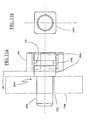
- This 186b insert has the distinction of having a 188b section pin square, the shoulder 179b of which protrudes from the sleeve 140, when it is mounted in this one.
- This arrangement makes it possible to offset the operating mechanism 190b of the type belt pulley mounted on a journal 187b of said cheek insert 186b 100 shown in thin lines in FIG. 11a.
- the assembly consisting of: the insert 186b and the sleeve 140 in each housing 130 of the two cheeks 100 of the shuttering devices of the tunnel safe to be fitted, in the same way as was previously described.
- the roller shutter axis is fitted at each of its ends with a nozzle, for example fully retractable type.
- the pulley with strap of the actuating mechanism 190b of the pulley type with strap fits on the head of the nozzle.
- Each end piece fits onto the pin 187b of the insert 186b by being retracted from the axis of a stroke limited by the shoulder 179b on said tip.
- the roller shutter deck is put in place as in the first example.
- the assembly of the components of the roller shutter, of a third manufacturer of accessories C, in a tunnel safe, enabled by the shutter device according to the invention is done by manual assembly and does not require the use tooling.
- a fourth example of mounting a roller shutter, with motor electric, in a tunnel safe according to the invention is described below with the constituents of a fourth manufacturer E.
- a motor support 192c is fixed by clipping to a sleeve 140c.
- the sleeve 140c comprises, in FIG. 12c, at least one accommodation of polygonal section 142c formed in protrusion of a shoulder 144c, and which is intended to allow centering and positioning in rotation of an opening of polygonal section 194c formed on the motor support 192c.
- Fig. 12a the external face of the shoulder 144c is positioned in the same plane that the internal face of the cheek 100 shown in fine lines.
- the housing of polygonal section 142c has at least one slot longitudinal in which is arranged an elastic tab 146c provided with a step 148c capable of clipping the polygonal section opening 194c, as this is also visible in FIG. 13a.
- the motor support 192c can be secured by clipping on the sleeve 140c.
- the operating mechanism of which is an electric motor in a tunnel safe, it is first necessary to fit in the housing 130 of the cheek of the shutter device, the sleeve 140c provided with the motor support 192c. Side opposite to the operating mechanism, a sleeve 140 having a concave square or polygonal shaped housing quadrilobe is clipped on the cheek 100 depending on whether a tip shaft is used shaped telescopic or a square telescopic end cap shaft.
- roller shutter axis fitted at one end with its electrical mechanism and at the other end of its telescopic tip shaft is put in place.
- the motor head is fitted and clipped into the motor support 192c and the tip shaft is fitted and clipped into the sleeve 140c.
- roller shutter curtain is put in place as in the examples precedents.
- the assembly of the components of the roller shutter of a fourth manufacturer of accessories in a tunnel safe is made by manual assembly, without the use of tools.
- exemplary embodiments of a rolling shutter assembly in a tunnel safe can be considered, especially those relating to different commercial tip tree shapes.
Abstract
Description
La présente invention concerne un dispositif obturateur fabriqué de préférence en matière plastique et destiné à fermer chacune des deux extrémités latérales d'un coffre-tunnel pour volet roulant.The present invention relates to a shutter device made of preferably plastic and intended to close each of the two ends sides of a rolling shutter tunnel tunnel.
Habituellement, les coffres-tunnels sont prévus pour être intégrés en cours de construction à la maçonnerie d'un bâtiment au-dessus des embrasures de fenêtre ou de porte, comme cela est montré à la Fig. 1.Usually, tunnel boxes are designed to be integrated during construction in the masonry of a building above window openings or door, as shown in Fig. 1.
Chaque coffre-tunnel est généralement constitué d'une coque moulée comportant un évidement en forme de tunnel dont la partie inférieure est ouverte pour permettre d'y loger un volet roulant.Each tunnel safe generally consists of a molded shell having a tunnel-shaped recess with the lower part open to accommodate a roller shutter.
Chaque dispositif obturateur constitué principalement d'une joue et d'un talon perpendiculaire à celle-ci, est prévu pour recevoir un volet roulant composé d'un axe de volet roulant, un tablier et des coulisses.Each obturator consisting mainly of a cheek and a heel perpendicular to it, is designed to receive a rolling shutter composed of an axis roller shutter, apron and runners.
Un axe de volet roulant est un tube métallique cylindrique ou octogonal sur lequel peut venir s'accrocher le tablier. Ce tube est équipé à chacune de ses extrémités d'un embout introduit à force. Un arbre d'embout monté libre à rotation dans ledit embout est fixé à la joue par l'intermédiaire d'un accessoire support d'arbre. Suivant une autre technique du fabricant d'accessoires, l'embout d'arbre s'emmanche sur un pivot fixé sur l'accessoire support d'arbre dénommé support pivot. A roller shutter axis is a cylindrical or octagonal metal tube on which can hang on the deck. This tube is equipped with each of its ends of a nozzle inserted by force. A tip shaft mounted free to rotate in said endpiece is fixed to the cheek by means of a support accessory shaft. According to another technique from the accessory manufacturer, the shaft end can be fitted on a pivot fixed on the shaft support accessory called support pivot.
A une extrémité de l'axe de volet roulant, entre l'embout et le support d'arbre, prend place un mécanisme de manoeuvre manuel de type poulie à sangle ou treuil à manivelle.At one end of the roller shutter axis, between the end piece and the support shaft, takes place a manual operating mechanism of the pulley type with strap or crank winch.
Ce dernier peut être compensé pour faciliter son utilisation en fonction de la surface ou du poids du tablier. La compensation est réalisée sur l'arbre de l'embout opposé au mécanisme de manoeuvre.The latter can be compensated to facilitate its use depending on the surface or weight of the deck. Compensation is carried out on the tip shaft opposite to the operating mechanism.
Lorsque l'axe de volet roulant est motorisé par un mécanisme de manoeuvre motorisé, l'ensemble moteur inclut l'embout. L'accessoire support d'arbre est alors spécifique côté moteur et dénommé support moteur.When the roller shutter axis is motorized by an operating mechanism motorized, the motor assembly includes the nozzle. The shaft support accessory is then specific on the engine side and called the engine support.
Côté opposé au mécanisme de manoeuvre, l'embout est généralement télescopique de manière à pouvoir faire varier la longueur totale de l'axe de volet roulant équipé lors de son introduction dans l'évidement du coffre-tunnel dont l'ouverture est réduite par la présence des talons.Opposite side of the operating mechanism, the tip is generally telescopic so that the total length of the flap axis can be varied rolling equipped when introduced into the recess of the tunnel box, the opening is reduced by the presence of the heels.
Les faces internes des joues incluent des réservations prévues pour permettre la fixation par vis des accessoires supports d'arbre, supports pivot, supports moteur ou pour immobiliser le treuil dans l'angle souhaité de raccordement à une genouillère équipée de sa manivelle (90 ° ou 75 °).The inner faces of the cheeks include reservations provided to allow screw fixing of the shaft support accessories, pivot supports, engine supports or to immobilize the winch in the desired angle of connection to a knee lifter equipped with its crank (90 ° or 75 °).
Il existe plusieurs fabricants d'accessoires et de mécanismes de manoeuvre, chacun ayant des types de montage et des entraxes de fixation différents. Cette particularité exige de prévoir un nombre important de réservations sur la joue, c'est-à-dire en moyenne, entre soixante et quatre-vingts.There are several manufacturers of accessories and operating mechanisms, each with different types of mounting and fixing centers. This particularity requires to provide a large number of reservations on the cheek, that is to say on average, between sixty and eighty.
Le mécanisme de manoeuvre, qu'il soit manuel ou motorisé, permet d'entraíner en rotation l'axe de volet roulant tel que décrit et sur lequel est fixé le tablier du volet roulant. Ainsi pour fermer l'embrasure le tablier se déroule autour de l'axe de volet roulant à la descente en coulissant dans des profilés en forme de U, communément appelés coulisses.The operating mechanism, whether manual or motorized, allows to rotate the roller shutter axis as described and on which is fixed the roller shutter deck. So to close the doorway the apron unrolls around the roller shutter axis on descent by sliding in U-shaped profiles, commonly known as backstage.
Lorsque les coulisses sont fixées sur la menuiserie devant celle-ci, le tablier s'enroule vers l'extérieur. Ce montage est de type à : «enroulement extérieur».When the slides are fixed to the joinery in front of it, the apron wraps outward. This assembly is of the “outside winding” type.
Lorsque les coulisses sont fixées sur la maçonnerie des tableaux de l'ouverture, le tablier s'enroule vers l'intérieur. Ce montage est de type à : «enroulement intérieur».When the slides are fixed on the masonry of the switchboards opening, the apron rolls inwards. This assembly is type of: "internal winding".
Pour réaliser l'incorporation d'un volet roulant, manoeuvré par exemple par un treuil dans un coffre-tunnel muni de ses dispositifs obturateurs, il faut, au préalable, fixer par vissage dans les réservations spécifiques prévues sur la paroi interne de chacune des joues, et après l'avoir centré, l'accessoire support d'arbre qui dans l'exemple choisi ci-dessous, est un coussinet à broche.To incorporate a rolling shutter, operated for example by a winch in a tunnel box fitted with its closing devices, it is necessary, at prior, fix by screwing in the specific reservations provided on the wall internal of each cheek, and after having centered it, the shaft support accessory which in the example chosen below, is a pin bearing.
Ce coussinet à broche comporte un doigt positionné parallèlement à la joue et dont l'extrémité libre doit être orientée vers la voûte du coffre-tunnel. Ce doigt est destiné à permettre l'accrochage d'une extrémité de l'arbre d'embout par un trou percé radialement dans celui-ci.This pin cushion has a finger positioned parallel to the cheek and the free end of which must point towards the roof of the tunnel safe. This finger is intended to allow the attachment of one end of the endpiece shaft by a drilled hole radially in it.
L'extrémité non télescopique de l'arbre support est montée au travers du mécanisme de manoeuvre puis est accrochée au coussinet à broche d'une joue. Le mécanisme de manoeuvre est ensuite orienté convenablement puis est fixé par des vis contre la paroi interne de ladite joue.The non-telescopic end of the support shaft is mounted through the operating mechanism then is hooked to the pin cushion of a cheek. The operating mechanism is then properly oriented and then fixed with screws against the inner wall of said cheek.
Une goupille est ensuite emmanchée dans le coussinet à broche pour éviter que ladite extrémité ne se décroche pendant le fonctionnement du volet roulant.A pin is then fitted into the pin pad to prevent that said end does not come off during the operation of the shutter.
La même opération est réalisée pour l'extrémité télescopique de l'arbre d'embout dont la course sera immobilisée par une bague vissée après avoir été accrochée sur le coussinet à broche.The same operation is carried out for the telescopic end of the shaft end cap whose stroke will be immobilized by a screwed ring after being hung on the pin pad.
Une goupille est également emmanchée dans ce coussinet à broche pour éviter le décrochement ultérieur de ladite extrémité télescopique.A pin is also fitted into this pin cushion for avoid the subsequent detachment of said telescopic end.
Cette technique de mise en place des constituants du volet roulant dans un coffre-tunnel déjà intégré à la maçonnerie, n'est pas aisée à réaliser sur chantier, du fait de la position peu ergonomique de l'opérateur, de la faible visibilité et accessibilité à l'intérieur de l'évidement du coffre-tunnel.This technique of placing the components of the roller shutter in a tunnel tunnel already integrated into the masonry, is not easy to achieve on site, from made of the operator's not very ergonomic position, the poor visibility and accessibility inside the tunnel-tunnel recess.
Pour pallier à ces difficultés, les fabricants de fermetures font la promotion du coffre-tunnel livré sur chantier déjà équipé de son volet roulant monté en atelier. En effet, le coffre-tunnel peut être disposé à bonne hauteur, retourné, c'est-à-dire avec son évidement exposé vers le haut pour faciliter la mise en place et la fixation des constituants du volet roulant.To overcome these difficulties, the manufacturers of fasteners are promoting tunnel-safe delivered to site already equipped with its rolling shutter fitted in the workshop. In Indeed, the tunnel safe can be placed at the right height, turned upside down, i.e. with its recess exposed upwards to facilitate the positioning and fixing of the components of the roller shutter.
Cette technique est possible si le tablier est monté «enroulement extérieur», c'est-à-dire, se déroulant devant la menuiserie avec les lames du tablier se présentant à l'envers.This technique is possible if the deck is mounted "outside winding", that is to say, taking place in front of the joinery with the blades of the deck appearing Upside down.
Cependant, lors des manutentions ou du transport, il arrive que le coffre et/ou le volet roulant soient détériorés au regard de la masse des constituants et sous l'effet des chocs.However, during handling or transport, the trunk and / or the roller shutter are deteriorated with regard to the mass of the constituents and under the effect shocks.
Par ailleurs, lorsque le coffre-tunnel muni de son volet roulant est intégré aux éléments de la maçonnerie en cours de construction, les constituants sont exposés aux projections de ciment ou d'enduit de façade inhérentes aux travaux du maçon ou de l'enduiseur. Il en découle une mauvaise présentation.Furthermore, when the tunnel-trunk fitted with its rolling shutter is integrated into the elements of the masonry under construction, the components are exposed projections of cement or facade plaster inherent in the mason's work or of the plasterer. This results in poor presentation.
Il arrive également que lors de la pose du coffre-tunnel muni de son volet roulant, le coffre-tunnel ne soit pas correctement centré par rapport à l'ouverture.It also happens that when installing the tunnel safe with its flap rolling, the tunnel box is not correctly centered in relation to the opening.
Une intervention ultérieure sur chantier sera nécessaire pour adapter la dimension du tablier, ce qui diminue l'intérêt du montage du volet en atelier.Subsequent intervention on site will be necessary to adapt the size of the apron, which reduces the advantage of mounting the shutter in the workshop.
D'autre part, la mise en place du volet roulant sur chantier dans un coffre-tunnel déjà intégré à la maçonnerie reste la solution la mieux adaptée lorsque le tablier est «enroulement intérieur», c'est-à-dire que les coulisses sont posées sur la maçonnerie de tableaux et que les lames du tablier se présentent dans le sens normal.On the other hand, the installation of the rolling shutter on site in a tunnel-safe already integrated into the masonry remains the most suitable solution when the apron is "internal winding", that is to say that the slides are placed on the masonry of tables and that the slats of the apron are facing in the normal direction.
Dans cette situation, la largeur prévue du tablier n'est définitive que lorsque les enduits des tableaux sont terminés.In this situation, the planned width of the deck is only final when the coatings of the paintings are finished.
On connaít également le document DE-U-94 09 619 qui présente un mécanisme d'entraínement d'un arbre de volet roulant. Le mécanisme est constitué d'une joue montée dans une extrémité d'un coffret. L'extrémité de l'arbre qui est destinée à être entraínée est montée, par l'intermédiaire d'un axe dans un roulement qui est logé dans une protubérance de la joue.We also know the document DE-U-94 09 619 which presents a mechanism for driving a tree roller shutter. The mechanism consists of a cheek mounted in one end of a cabinet. The end of the shaft which is intended to be driven is mounted, by means of an axis in a bearing which is housed in a protrusion of the cheek.
Le but de l'invention est donc de proposer un dispositif obturateur pour coffre-tunnel pour volet roulant qui permette un montage in situ des constituants du volet roulant dans le coffre-tunnel qui soit aussi aisé et rapide qu'un montage en atelier et qui supprime les tâtonnements et les risques d'erreurs de mauvais positionnement de ses constituants.The object of the invention is therefore to propose a shutter device for rolling shutter tunnel for in-situ mounting of the components of the roller shutter in the tunnel box that is as easy and quick as mounting in workshop and that removes the guesswork and the risk of wrong mistakes positioning of its constituents.
Un autre but de l'invention est de proposer un dispositif obturateur pour coffre-tunnel pour volet roulant qui permette un montage de type universel pouvant s'adapter à tous les types de volet roulant.Another object of the invention is to propose a shutter device for rolling shutter tunnel for universal mounting that can adapt to all types of roller shutters.
A cet effet, le dispositif obturateur destiné à fermer une extrémité latérale d'un coffre-tunnel pour volet roulant, ledit obturateur étant constitué notamment d'une joue associée à un talon, est remarquable en ce que la joue comporte un logement formé en protubérance de la face externe de la joue et destiné à recevoir intérieurement un manchon comportant un logement de section polygonale permettant de loger une extrémité conformée d'un arbre d'embout de volet roulant ou d'une broche d'un insert ou un support moteur.To this end, the shutter device intended to close a lateral end of a rolling shutter tunnel, said shutter being constituted in particular of a cheek associated with a heel, is remarkable in that the cheek has a housing formed in protrusion of the outer face of the cheek and intended to receive internally a sleeve comprising a housing of polygonal section for accommodating a shaped end of a rolling shutter end shaft or an insert pin or an engine mount.
Ainsi, le montage des constituants du volet roulant dans le coffre-tunnel est simplifié et rationalisé.Thus, the assembly of the components of the rolling shutter in the tunnel safe is simplified and streamlined.
Selon une autre caractéristique de l'invention, le logement est cylindrique et comporte au moins un crantage qui est formé longitudinalement et en relief sur la paroi interne dudit logement cylindrique, ledit crantage permettant de chevaucher respectivement une encoche formée sur l'enveloppe du manchon pour permettre le positionnement en rotation dudit manchon dans le logement cylindrique. According to another characteristic of the invention, the housing is cylindrical and comprises at least one notch which is formed longitudinally and in relief on the internal wall of said cylindrical housing, said notching making it possible to overlap respectively a notch formed on the envelope of the sleeve to allow the positioning in rotation of said sleeve in the cylindrical housing.
Selon une autre caractéristique de l'invention, le logement comporte une gorge jouxtant le fond du logement permettant de loger un redan formé sur un ergot disposé à l'extrémité d'un doigt élastique formé dans une découpe réalisée dans une encoche de l'enveloppe du manchon de manière à bloquer en translation le manchon dans le logement cylindrique.According to another characteristic of the invention, the housing comprises a groove adjoining the bottom of the housing for housing a step formed on a lug disposed at the end of an elastic finger formed in a cut made in a notch in the sleeve casing so as to block the sleeve in translation in the cylindrical housing.
Selon une autre caractéristique de l'invention, le manchon comporte un point d'ancrage formé sur l'ergot permettant à un outil ayant traversé une ouverture réalisée au travers d'un épaulement dudit manchon de déformer le doigt élastique en agissant sur ledit point d'ancrage pour faire ressortir le redan de la gorge et permettre l'extraction du manchon du logement.According to another characteristic of the invention, the sleeve has a point anchor formed on the lug allowing a tool having passed through an opening made through a shoulder of said sleeve to deform the elastic finger by acting on said anchor point to bring out the step of the gorge and allow extracting the sleeve from the housing.
Selon une autre caractéristique de l'invention, le dispositif obturateur dont la joue comporte une platine est remarquable en ce qu'un conduit est réalisé dans la platine, ledit conduit débouchant, d'une part, dans la face interne de la joue et, d'autre part, à l'intérieur du logement pour permettre l'introduction d'un outil dans le logement pour agir sur le point d'encrage.According to another characteristic of the invention, the shutter device, the cheek has a plate is remarkable in that a conduit is made in the platinum, said duct opening, on the one hand, into the internal face of the cheek and, on the other hand part, inside the housing to allow the introduction of a tool in the housing to act on the anchoring point.
Selon une autre caractéristique de l'invention, le manchon comporte un ergot pourvu d'un redan formé sur un doigt élastique formé dans une découpe réalisée au travers d'un côté du logement de section polygonale permettant audit redan de se loger dans un orifice ou dans une gorge réalisés respectivement dans l'extrémité conformée ou dans l'insert, de manière à bloquer respectivement axialement l'arbre d'embout ou l'insert dans le logement de section polygonale du manchon, par clippage.According to another characteristic of the invention, the sleeve comprises a lug provided with a step formed on an elastic finger formed in a cut made in through one side of the housing of polygonal section allowing said step to be lodge in an orifice or in a groove made respectively in the end shaped or in the insert, so as to lock the shaft respectively axially tip or insert in the polygonal section of the sleeve, by clipping.
Selon une autre caractéristique de l'invention, le manchon comporte un point d'ancrage formé à l'extrémité libre du doigt élastique permettant à un outil ayant traversé une ouverture réalisée au travers de l'épaulement de déformer le doigt élastique pour faire ressortir l'ergot de l'orifice pour permettre l'extraction de l'arbre d'embout ou de l'insert du manchon.According to another characteristic of the invention, the sleeve has a point anchor formed at the free end of the elastic finger allowing a tool having crossed an opening made through the shoulder to deform the finger elastic to bring out the lug of the hole to allow the extraction of the shaft tip or sleeve insert.
Selon une autre caractéristique de l'invention, le logement de section polygonale a une section carrée.According to another characteristic of the invention, the sectional housing polygonal has a square section.
Selon une autre caractéristique de l'invention, le logement de section polygonale est un polygone concave a section polygonale concave de forme quadrilobe.According to another characteristic of the invention, the sectional housing polygonal is a concave polygon with a concave polygonal section of shape quatrefoil.
Les caractéristiques de l'invention mentionnées ci-dessus, ainsi que d'autres,
apparaítront plus clairement à la lecture de la description suivante d'un exemple de
réalisation, ladite description étant faite en relation avec les dessins joints, parmi
lesquels:
Le coffre-tunnel 400 représenté à la Fig. 1 est prévu pour être intégré dans la maçonnerie M au-dessus de l'embrasure d'une fenêtre ou d'une porte d'un bâtiment. Il est en particulier encastré dans la maçonnerie M par ses deux extrémités latérales 402 et 404 et par la voûte V.The tunnel safe 400 shown in FIG. 1 is intended to be integrated into the masonry M above the doorway of a window or door of a building. he is in particular embedded in the masonry M by its two lateral ends 402 and 404 and through the vault V.
Il est intégré dans la maçonnerie M de telle manière que l'évidement interne
du coffre-tunnel 400 débouche dans ladite embrasure. It is integrated into the masonry M in such a way that the internal recess
of the safe-
Le dispositif obturateur D représenté à la Fig. 2 est globalement constitué
d'une joue 100, d'un talon 300 et d'un élément d'ancrage 200.The shutter device D shown in FIG. 2 is globally constituted
a
Le dispositif obturateur D est destiné à être monté latéralement dans chacune
des extrémités 402 ou 404 d'un coffre-tunnel 400 de façon à fermer de manière
étanche à l'air provenant de l'évidement interne du coffre-tunnel, ladite extrémité
latérale 402 ou 404 dudit coffre-tunnel 400.The shutter device D is intended to be mounted laterally in each
ends 402 or 404 of a tunnel safe 400 so as to close so
airtight from the internal recess of the tunnel safe, said
Le coffre-tunnel 400 est représenté par des cellules en nids d'abeilles aux Figs. 2, 6, 7 et 8.The tunnel safe 400 is represented by honeycomb cells with Figs. 2, 6, 7 and 8.
A la Fig. 2, le coffre-tunnel 400 est constitué d'une coque à base de
polystyrène délimitée en longueur par deux extrémités latérales 402 et 404. Une
seule extrémité latérale 402 est visible à cette Fig.In Fig. 2, the tunnel safe 400 consists of a shell based on
polystyrene delimited in length by two lateral ends 402 and 404. A
only
La joue 100 du dispositif obturateur D comprend une platine 120 sur laquelle
est disposée perpendiculairement une bordure d'appui 110.The
La bordure d'appui 110 est prévue pour épouser intimement les parois
internes de la voûte V et des jambages J1 et J2 du coffre-tunnel, de manière à assurer
le positionnement précis de la joue 100 par rapport à une extrémité latérale 402 ou
404 du coffre-tunnel 400. A la Fig. 2, seul le jambage J2 est visible dans cette vue en
coupe.The
La platine 120 est prolongée à sa périphérie dans un même plan par une
collerette 126 perpendiculaire à la bordure d'appui 110.The
La collerette 126 est destinée à entrer en contact avec une extrémité latérale
402 ou 404 d'un coffre-tunnel 400 pour servir de butée axiale au dispositif obturateur
D lors de son montage. De ce fait, elle est également apte à former une barrière
étanche au passage de l'air entre l'évidement interne du coffre-tunnel 400 et un
doublage isolant intérieur du bâtiment.The
Un talon 300 est raccordé dans la partie basse de la platine 120 d'une joue 100
de manière perpendiculaire à ladite joue 100 pour former un dispositif obturateur D
monobloc.A
Le talon 300 est destiné à supporter la masse du volet roulant accroché à la
platine 120 de la joue 100 en prenant appui sur l'assise de la maçonnerie M prévue à
cet effet.The
Le talon 300 permet également de soutenir le coffre-tunnel 400 lors de son
intégration dans la maçonnerie M. The
Un élément d'ancrage 200 peut être inséré dans la partie de la bordure d'appui
110 destinée à entrer en contact avec la voûte V d'un coffre-tunnel 400, de manière à
lier mécaniquement la joue 100 avec la voûte V du coffre-tunnel 400, après que le
dispositif obturateur D ait été monté dans une extrémité latérale 402 ou 404 dudit
coffre-tunnel 400.An
La platine 120 comporte dans sa partie centrale un logement 130 formé en
protubérance de la face externe de la platine 120. A cette Fig., le logement 130 a une
section polygonale concave de forme quadrilobe.The
Ce logement 130 est destiné à recevoir un manchon 140 pouvant loger une
première extrémité conformée 182 d'un arbre d'embout 180 de volet roulant. A la
Fig. 2, la première extrémité conformée 182 a une section carrée.This
A la Fig. 3, le logement 130 comprend des crantages 132 visibles également à
la Fig. 7 qui sont formés longitudinalement et en relief sur la paroi interne dudit
logement 130. Ces crantages 132 sont répartis régulièrement sur ladite paroi interne.In Fig. 3, the
Ces crantages 132 sont délimités, d'une part, par une couronne 134 réalisée à
l'entrée du logement 130 et, d'autre part, par une gorge 136 jouxtant le fond 138 du
logement 130.These
Un chanfrein d'entrée 139 est également réalisé sur les crantages 132 à
l'entrée du logement 130.An
Aux Figs. 4a, et 13a, le manchon 140 est constitué d'une enveloppe 142 de
préférence de section cylindrique pouvant se loger dans le logement 130 décrit à la
Fig. 3. Aux Figs. 4a et 13a, un épaulement 144 est formé à une extrémité de
l'enveloppe 142 et peut se loger dans la couronne 134 du logement 130 pour servir de
butée axiale lors du montage du manchon 140 dans le logement 130.In Figs. 4a, and 13a, the
Des encoches 146 sont formées longitudinalement en creux sur l'enveloppe
142 et sont réparties régulièrement sur ladite enveloppe 142. Ces encoches 146 sont
destinées à chevaucher respectivement les crantages 132 de manière à permettre un
blocage en rotation du manchon 140 dans le logement 130.
Un chanfrein 148 est réalisé sur l'autre extrémité de l'enveloppe 142 afin de
faciliter le montage du manchon 140 dans le logement 130.A
Aux Figs. 4b et 13b, un logement de section polygonale 150 traverse
longitudinalement le manchon 140 et admet le logement de la première extrémité
conformée 182 de l'arbre d'embout 180. A la Fig. 4b, le logement de section
polygonale 150 a une section carrée permettant de loger une tel qu'il est représenté à
la Fig. 10.In Figs. 4b and 13b, a housing of
A la Fig. 13b, le logement de section polygonale 150 a section polygonale
concave de forme quadrilobe permettant de loger une extrémité 182 conformée d'un
arbre d'embout 180, comme cela est montré aux Figs. 2, 5 et 14.In Fig. 13b, the housing of
A la Fig. 4b, un premier doigt élastique 152 est formé dans une découpe
réalisée au travers d'un côté 154 du logement de section polygonale 150. Ce premier
doigt élastique 152 est désolidarisé partiellement et latéralement de la découpe
réalisée au travers d'un côté 154 pour obtenir une élasticité de ses parois qui vont
fonctionner comme un clip.In Fig. 4b, a first
Le premier doigt élastique 152 comporte à la Fig. 5 un ergot 156 pourvu d'un
redan 158 qui ressort naturellement dudit coté 154.The first
Ce redan 158 peut alors, à l'issue du logement de la première extrémité
conformée 182 de l'arbre d'embout 180 dans le logement de section polygonale 150,
se loger dans un orifice 184 réalisé dans ladite extrémité conformée 182, de manière
à bloquer axialement l'arbre d'embout 180 dans le logement de section polygonale
150 du manchon 140, par clippage.This
Une première ouverture 160 réalisée au travers de l'épaulement 144 permet le
passage d'un outil, par exemple l'extrémité d'un tournevis non représenté, afin qu'il
puisse agir par arc-boutement sur un point d'encrage 162, constitué par exemple à la
Fig. 5 d'un orifice 162, réalisé à l'extrémité libre du premier doigt élastique 152. De
cette manière, l'outil peut déformer ledit doigt élastique 152 afin de faire ressortir le
redan 158 de l'orifice 184 pour permettre l'extraction de la première extrémité
conformée 182 de l'arbre d'embout 180 du logement de section polygonale 150.A
A la Fig. 4b, un second doigt élastique 164 est formé dans une découpe
réalisée dans une encoche 146 de l'enveloppe 142 du manchon 140.In Fig. 4b, a second
Ce second doigt élastique 164 comporte à la Fig. 5 un ergot 166 pourvu d'un
redan 168.This second
Ce redan 168 peut alors, à l'issue du logement du manchon 140 dans le
logement 130, se loger dans la gorge 136 de manière à bloquer en translation le
manchon 140 dans le logement 130.This
Une seconde ouverture 170 réalisée au travers de l'épaulement 144 permet le
passage d'un outil, par exemple l'extrémité d'un tournevis non représenté, afin qu'il
puisse agir par arc-boutement sur un point d'encrage 172, constitué par exemple à la
Fig. 5 d'une face d'appui 172, réalisée à l'extrémité libre du second doigt élastique
164. De cette manière, l'outil peut déformer le second doigt élastique 164 et faire
ressortir le redan 168 de la gorge 136 pour permettre l'extraction du manchon 140 du
logement 130.A
Pour faciliter le passage de l'outil, une variante d'accès au point d'encrage
172, constituée d'un conduit 170a est réalisée dans la platine 120 de la joue 100 à la
Fig. 7. Ce conduit 170a débouche, d'une part, dans la face interne de la joue 100 dans
sa partie basse et, d'autre part, à l'intérieur du logement 130. Ainsi l'outil peut être
introduit dans le logement 130 pour agir sur le point d'encrage 172. Ce conduit 170a
a la particularité de ne pas traverser la joue 100, ce qui permet de conserver étanche
la joue 100 lors du coulage d'un liant contre la face externe de ladite joue 100 pour la
solidariser à la maçonnerie d'un bâtiment.To facilitate the passage of the tool, a variant of access to the
Un premier exemple de réalisation du montage d'un volet roulant dans un coffre-tunnel suivant l'invention est décrit ci-après avec les constituants d'un premier fabricant d'accessoires A.A first example of how to assemble a rolling shutter in a tunnel-vault according to the invention is described below with the constituents of a first accessories manufacturer A.
Un mécanisme de manoeuvre 190 constitué à la Fig. 6 d'un treuil à manivelle
est assemblé contre la face interne de la joue 100.An
Ce mécanisme de manoeuvre 190 comporte un entraíneur à crabot 192 pourvu
d'un logement central 194.This
L'entraíneur à crabot 192 est prévu pour se loger dans un embout monté sur
l'axe de volet roulant pour permettre l'entraínement en rotation dudit axe de volet
roulant autour duquel s'enroule le tablier du volet roulant. L'axe de volet roulant et le
tablier ne sont pas représentés.The
Le logement central 194 peut être traversé par l'arbre d'embout 180 lors du
logement de la première extrémité conformée 182 de l'arbre d'embout 180 dans le
logement de section polygonale 150 afin de permettre le centrage du mécanisme de
manoeuvre 190 par rapport à la face interne de la joue 100, comme cela apparaít à la
Fig. 2.The
A la Fig. 6, le mécanisme de manoeuvre 190 comporte également un moyen
de fixation 196 tel qu'une ou plusieurs vis 196 à cette Fig., et qui est destiné à
immobiliser l'orientation du mécanisme de manoeuvre 190 par rapport à la face
interne de la joue 100 dans l'angle souhaité de raccordement à la genouillère équipée
de sa manivelle (75 ° ou 90 °). A cet effet, les vis, au nombre de deux à cette Fig.,
sont logées respectivement dans des orifices réalisés de part et d'autre d'un palier de
l'axe de manoeuvre du treuil à manivelle et se vissent dans des réservations 122
prévues dans la face interne de la joue 100.In Fig. 6, the
A titre d'exemple, l'axe de manoeuvre du treuil à manivelle est positionné à
cette Fig. avec un angle de 75° par rapport à l'axe vertical de la joue 100.For example, the operating axis of the crank winch is positioned at
this Fig. at an angle of 75 ° to the vertical axis of the
Comme on peut le remarquer à la Fig. 7, ces réservations 122 sont disposées
en arc de cercle autour du logement 130, ce qui permet de positionner un même
mécanisme de manoeuvre 190 dans une position angulaire différente, ou de permettre
le positionnement angulaire d'un autre type de mécanisme de manoeuvre 190 contre
la face interne de la joue 100.As can be seen in FIG. 7, these
A la Fig. 14, la seconde extrémité conformée de l'arbre d'embout est montée de manière télescopique par rapport à l'embout. Cette seconde extrémité conformée de l'arbre d'embout peut recevoir un mécanisme de compensation de charge, non représenté, et destiné à réduire le couple de manoeuvre lors de l'entraínement en rotation du tablier par le mécanisme de manoeuvre.In Fig. 14, the second shaped end of the endpiece shaft is mounted telescopically to the end piece. This second shaped end of the tip shaft can receive a load compensation mechanism, not shown, and intended to reduce the operating torque during training in rotation of the deck by the operating mechanism.
A cette différence près, la seconde extrémité conformée de l'arbre d'embout
est assemblée à sa joue respective de la même manière que la première extrémité 182
l'est avec la joue 100.With this difference, the second shaped end of the tip shaft
is assembled to his respective cheek in the same way as the
Pour réaliser le montage des constituants du volet roulant dans le coffre-tunnel
préalablement intégré à une maçonnerie M d'un bâtiment, il faut, dans un
premier temps, monter un manchon 140 tel qu'il est représenté aux Fig. 13a, 13b, 13c
dans chaque logement 130 d'une joue 100, de manière à ce que le redan 168 du
second doigt élastique 164 puisse se loger dans la gorge 136 dudit logement 130 pour
permettre le clippage du manchon 140 dans ledit logement 130. Les encoches 146
chevauchent alors respectivement les crantages 132, ce qui assure un blocage en
rotation du manchon 140 dans son logement 130.To mount the components of the roller shutter in the tunnel safe
previously integrated into a masonry M of a building, it is necessary, in a
first, mount a
Il faut, dans un second temps, introduire dans l'évidement du coffre-tunnel
400, l'ensemble formé par l'axe de volet roulant équipé à une extrémité d'un embout
muni de son arbre télescopique éventuellement compensé représenté à la Fig. 14, et à
l'autre extrémité, représenté à la Fig. 5, d'un embout muni de son arbre d'embout 180
engagé dans le logement central 194 d'un mécanisme de manoeuvre 190 jusqu'à ce
que l'entraíneur à crabot 192 soit logé dans l'embout.It is necessary, in a second step, to introduce into the recess of the tunnel safe
400, the assembly formed by the roller shutter axis fitted at one end with a nozzle
fitted with its possibly compensated telescopic shaft shown in FIG. 14, and to
the other end, shown in FIG. 5, a tip provided with its
La première extrémité conformée 182 de l'arbre d'embout 180, montée au
travers d'un mécanisme de manoeuvre 190, est logée dans le logement de section
polygonale 150 du manchon 140 tel qu'il est représenté aux Figs. 13a, 13b, 13c. A cet
effet, la première extrémité conformée 182 est orientée de manière à ce que l'ergot
156 du manchon 140 puisse se loger dans l'orifice 184 réalisé dans ladite extrémité
conformée 182. A ce moment, la première extrémité conformée 182 est liée
mécaniquement avec le manchon 140, et par conséquent, avec la joue 100 d'un
dispositif obturateur D.The first
La seconde extrémité conformée de l'arbre d'embout est assemblée à sa joue
respective de la même manière que la première extrémité conformée 182 l'est avec la
joue 100.The second shaped end of the tip shaft is assembled to his cheek
respective in the same way as the first
Le mécanisme de manoeuvre 190 est ensuite positionné en rotation puis fixé
sur la face interne de la joue 100 par le moyen de fixation 196.The
Le tablier du volet roulant est ensuite fixé à l'axe par des attaches de tablier dont l'extrémité opposée au tablier est conçue pour s'encastrer dans une réservation prévue sur le tube de l'axe.The roller shutter deck is then fixed to the axis by deck ties whose end opposite the deck is designed to fit into a reservation provided on the axle tube.
Le montage des constituants du volet roulant dans un coffre-tunnel permis par le dispositif obturateur selon l'invention se fait par assemblage manuel et ne nécessite pas l'utilisation d'outillage, excepté un tournevis pour la mise en place d'un ou deux moyens de fixation 196 du mécanisme treuil.The assembly of the components of the roller shutter in a tunnel-safe permitted by the shutter device according to the invention is made by manual assembly and does not require no use of tools, except a screwdriver for the installation of one or two fixing means 196 of the winch mechanism.
Le montage de ces constituants ne peut s'opérer que lorsqu'ils sont correctement positionnés.The assembly of these components can only take place when they are correctly positioned.
Un deuxième exemple de réalisation du montage d'un volet roulant avec un
mécanisme de manoeuvre 190a de type à treuil dans un coffre-tunnel suivant
l'invention est décrit ci-après avec les constituants d'un deuxième fabricant
d'accessoires B. La particularité réside dans le fait que l'embout de l'axe du volet
roulant côté mécanisme se comporte comme un moyeu qui, après avoir traversé ledit
mécanisme, vient s'emboíter sur un tourillon.A second embodiment of the assembly of a roller shutter with a
winch
Dans cette première variante de réalisation représentée à la Fig. 8, un insert
186a est logé dans un manchon 140 monté dans le logement 130 d'une joue 100.In this first alternative embodiment shown in FIG. 8, an
A à la Fig. 9a, l'insert 186a est constitué d'un tourillon 187a prévu pour se
loger dans la première extrémité d'un embout d'axe de volet roulant non représentés à
la Fig. 8.A in Fig. 9a, the
A la Fig. 9a, ce tourillon 187a est prolongé de manière coaxiale par une
broche de section carrée 188a, représentée également à la Fig. 9b et dont la
dimension lui permet de se loger dans le logement de section polygonale 150 du
manchon 140 représenté aux Figs. 9c et 9d. In Fig. 9a, this
Aux Fig. 9a et 9c, une gorge 189a est réalisée à la périphérie de la broche
188a. Cette gorge 189a est destinée à recevoir l'ergot 156 du premier doigt élastique
152 d'un manchon 140, comme cela est représenté à la Fig. 9c.In Figs. 9a and 9c, a
Pour réaliser le montage des constituants du volet roulant dans le coffre-tunnel,
il faut, dans un premier temps, emboíter un insert 186a dans le logement de
section polygonale 150 du manchon 140, jusqu'à ce que l'ergot 156 du doigt 152 soit
logé dans la gorge 189aTo assemble the components of the roller shutter in the tunnel safe,
it is necessary, firstly, to insert an
Dans un second temps, il est possible de monter l'ensemble constitué par
l'insert 186a et le manchon 140 représenté aux Fig. 4a et 4b dans le logement 130
d'une des deux joues 100 des dispositifs obturateurs du coffre-tunnel à équiper et un
manchon 140, comportant un logement de section polygonale 150 et de section
carrée dans le logement 130 de l'autre joue 100.In a second step, it is possible to mount the assembly constituted by
the
Ensuite, il faut mettre en place comme précédemment l'axe du volet roulant
équipé à une de ses extrémités de l'embout engagé dans le mécanisme de manoeuvre
190a de type à treuil et équipé à l'autre extrémité d'un arbre d'embout télescopique
de section carrée.Then, it is necessary to set up as previously the axis of the roller shutter
fitted at one of its ends with the endpiece engaged in the
Pour cela, l'embout, muni de son mécanisme 190a de type à treuil, est
emboíté sur le tourillon 187a de l'insert 186a. L'arbre d'embout télescopique 180g de
section carrée de l'axe de volet roulant, qui est visible uniquement à la Fig. 10 est
engagé dans le logement de section carré 150 du manchon 140, jusqu'à ce que l'ergot
156 soit logé dans l'orifice 184 réalisé dans l'extrémité dudit arbre d'embout. Puis
l'arbre d'embout télescopique 180g est immobilisé en extension par une bague de
serrage pour empêcher le déboítement de l'embout emboíté dans le mécanisme de
manoeuvre 190a de type à treuil.For this, the end piece, provided with its winch-
Le mécanisme de manoeuvre 190a de type à treuil, est ensuite orienté dans
l'angle souhaité, puis immobilisé sur la face interne de la joue 100 par le moyen de
fixation 196.The winch-
Dans ce deuxième exemple de réalisation, les deux manchons 140 comportant
respectivement un logement 150 de section carrée sont utilisés, soit côté mécanisme
de manoeuvre, soit côté opposé au mécanisme de manoeuvre 190a de type à treuil.In this second exemplary embodiment, the two
Le montage des constituants du volet roulant, d'un deuxième fabricant
d'accessoires B, dans un coffre-tunnel permis par le dispositif obturateur selon
l'invention, se fait par assemblage manuel et ne nécessite pas l'utilisation d'outillage,
excepté un tournevis pour la mise en place du moyen de fixation du mécanisme de
manoeuvre 190a de type à treuil.The assembly of the components of the roller shutter, from a second manufacturer
of accessories B, in a tunnel safe enabled by the shutter device according to
the invention is made by manual assembly and does not require the use of tools,
except a screwdriver for the installation of the fixing mechanism of the
Un troisième exemple du montage d'un volet roulant avec mécanisme de manoeuvre à poulie à sangle, dans un coffre-tunnel suivant l'invention, est décrit ci-après avec les constituants d'un troisième fabricant C.A third example of mounting a roller shutter with a mechanism pulley operation with strap, in a tunnel box according to the invention, is described below with the constituents of a third manufacturer C.
Pour réaliser un tel montage de volet roulant, il faut, dans un premier temps,
emboíter un insert 186b dans le logement de section carrée 150 d'un manchon 140,
jusqu'à ce que l'ergot 156 soit logé dans la gorge 189b, comme le montre la Fig. 11a.To make such a rolling shutter assembly, it is first necessary to
fitting an
Cet insert 186b a la particularité de posséder une broche 188b de section
carrée, dont l'épaulement 179b dépasse du manchon 140, lorsqu'il est monté dans
celui-ci. Cet agencement permet de décaler le mécanisme de manoeuvre 190b de type
poulie à sangle monté sur un tourillon 187b dudit insert 186b de la joue 100
représenté en trait fin à la Fig. 11a.This 186b insert has the distinction of having a 188b section pin
square, the
Dans un deuxième temps, on monte respectivement l'ensemble constitué par
l'insert 186b et le manchon 140 dans chaque logement 130 des deux joues 100 des
dispositifs obturateurs du coffre-tunnel à équiper, de la même manière que cela a été
décrit précédemment.In a second step, the assembly consisting of:
the
L'axe de volet roulant est équipé à chacune de ses extrémités d'un embout,
par exemple de type rétractile totalement engagé. Côté mécanisme de manoeuvre, la
poulie à sangle du mécanisme de manoeuvre 190b de type poulie à sangle s'emboíte
sur la tête de l'embout. Chaque embout vient s'emboíter sur le tourillon 187b de
l'insert 186b en étant rétracté de l'axe d'une course limitée par l'épaulement 179b sur
ledit embout.The roller shutter axis is fitted at each of its ends with a nozzle,
for example fully retractable type. On the operating mechanism side, the
pulley with strap of the actuating mechanism 190b of the pulley type with strap fits
on the head of the nozzle. Each end piece fits onto the
Puis le tablier du volet roulant est mis en place comme dans le premier exemple. Ainsi, le montage des constituants du volet roulant, d'un troisième fabricant d'accessoires C, dans un coffre-tunnel, permis par le dispositif obturateur selon l'invention, se fait par assemblage manuel et ne nécessite pas l'utilisation d'outillage.Then the roller shutter deck is put in place as in the first example. Thus, the assembly of the components of the roller shutter, of a third manufacturer of accessories C, in a tunnel safe, enabled by the shutter device according to the invention, is done by manual assembly and does not require the use tooling.
Un quatrième exemple de montage d'un volet roulant, avec moteur électrique, dans un coffre-tunnel suivant l'invention est décrit ci-après avec les constituants d'un quatrième fabricant E.A fourth example of mounting a roller shutter, with motor electric, in a tunnel safe according to the invention is described below with the constituents of a fourth manufacturer E.
A la Fig. 12a, un support moteur 192c est fixé par clippage à un
manchon 140c. In Fig. 12a, a
A cet effet, le manchon 140c comporte, à la Fig. 12c, au moins un logement
de section polygonale 142c formé en protubérance d'un épaulement 144c, et qui est
destiné à permettre le centrage et le positionnement en rotation d'une ouverture de
section polygonale 194c formée sur le support moteur 192c. On peut remarquer qu'à
la Fig. 12a, la face externe de l'épaulement 144c est positionnée dans un même plan
que la face interne de la joue 100 représentée en traits fins.To this end, the
Le logement de section polygonale 142c comporte au moins une fente
longitudinale dans laquelle est disposée une patte élastique 146c munie d'un redan
148c pouvant réaliser le clippage de l'ouverture de section polygonale 194c, comme
cela est également visible à la Fig. 13a.The housing of
A la Fig. 12b, trois pattes élastiques 146c sont représentées.In Fig. 12b, three
De cette manière, le support moteur 192c peut être solidarisé par clippage sur
le manchon 140c.In this way, the
Pour réaliser le montage du volet roulant dont le mécanisme de manoeuvre est
un moteur électrique, dans un coffre-tunnel, il faut, dans un premier temps, emboíter
dans le logement 130 de la joue du dispositif obturateur, le manchon 140c muni du
support moteur 192c. Côté opposé au mécanisme de manoeuvre, un manchon 140
comportant un logement de section carrée ou polygonale concave de forme
quadrilobe est clippé sur la joue 100 suivant qu'il est utilisé un arbre d'embout
télescopique conformé ou un arbre d'embout télescopique carré.To carry out the assembly of the roller shutter, the operating mechanism of which is
an electric motor, in a tunnel safe, it is first necessary to fit
in the
Dans un deuxième temps, l'axe de volet roulant équipé à une extrémité de
son mécanisme électrique et à l'autre extrémité de son arbre d'embout télescopique
est mis en place. La tête du moteur est emboítée et clippée dans le support moteur
192c et l'arbre d'embout est emboíté et clippé dans le manchon 140c.Secondly, the roller shutter axis fitted at one end with
its electrical mechanism and at the other end of its telescopic tip shaft
is put in place. The motor head is fitted and clipped into the
Puis, le tablier de volet roulant est mis en place comme dans les exemples précédents.Then, the roller shutter curtain is put in place as in the examples precedents.
Ainsi, le montage des constituants du volet roulant d'un quatrième fabricant d'accessoires dans un coffre-tunnel, permis par la joue du dispositif obturateur selon l'invention, se fait par assemblage manuel, sans utilisation d'outillage.Thus, the assembly of the components of the roller shutter of a fourth manufacturer of accessories in a tunnel safe, enabled by the side of the shutter device according to the invention is made by manual assembly, without the use of tools.
D'autres exemples de réalisation d'un montage de volet roulant dans un coffre-tunnel peuvent être envisagés, en particulier ceux concernant les différentes formes d'arbre d'embout du commerce.Other exemplary embodiments of a rolling shutter assembly in a tunnel safe can be considered, especially those relating to different commercial tip tree shapes.
Claims (9)
- Closure device (D) intended to blank off a lateral extremity (402, 404) of a box (400) for a roller shutter, said closure (D) being comprised in particular of a flange (100) associated with a lug (300), characterized in that the said flange (100) contains a first compartment (130) formed protruding from the flange (100) and intended to receive a sleeve (140, 140c) containing a second compartment (150, 142c) permitting the housing of a shaped extremity (182) of a rod-end pin (180) of a roller shutter or of a spindle (188a, 188b) of an insert (186a, 186b) or a motor support (192c).
- Closure device (D) according to claim 1, characterized in that the first compartment (130) is cylindrical and contains at least one notched element (132) which is formed longitudinally and in relief on the inner wall of the said first compartment (130), the said notched element (132) permitting the straddling respectively of a slot (146) formed on the envelope (142) of the sleeve (140, 140c) in order to permit the placing in rotation of the said sleeve (140, 140c) in the first compartment (130).
- Closure device (D) according to claim 1 or 2, characterized in that the first compartment (130) contains a groove (136) adjoining the bottom (138) of the first compartment (130) permitting the housing of a step (168) formed on a projection (166) placed at the end of an elastic finger (164) formed in a cut-out realized in a slot (146) of the envelope (142) of the sleeve (140, 140c) so as to block translatory movement of the sleeve (140, 140c) in the first compartment (130).
- Closure device (D) according to claim 3, characterized in that the sleeve (140, 140c) contains an anchorage point (172) formed on the projection (166) allowing a tool that has passed through an opening (170) realized through a shoulder (144, 144c) of the said sleeve (140, 140c) to deform the elastic finger (164) by acting on the said anchorage point (172) in order to cause the step (168) to leave the groove (136) and allow the extraction of the sleeve (140, 140c) from the first compartment (130).
- Closure device (D) according to claim 4 of which the flange (100) contains a plate (120), characterized in that a conduit (170a) is realized in the plate (120), the said conduit (170a) opening out, on one side, into the internal face of the flange (100) and, on the other side, on the inside of the first compartment (130) in order to permit the introduction of a tool into the first compartment (130) in order to act on the anchorage point (172).
- Closure device (D) according to any one of the previous claims, characterized in that the sleeve (140) contains a projection (156) provided with a step (158) formed on an elastic finger (152) formed in a cut-out realized through one side (154) of the second compartment (150) allowing the said step (158) to be accommodated in an orifice (184) or in a groove (189a, 189b) realized respectively in the shaped extremity (182) or in the insert (186a, 186b), so as to block respectively axially the rod-end pin (180) or the insert (186a, 186b) in the second compartment (150) of the sleeve (140), by means of clipping.
- Closure device (D) according to claim 6, characterized in that the sleeve (140, 140c) contains an anchorage point (162) formed at the free extremity of the elastic finger (152) allowing a tool that has passed through an opening (160) realized through the shoulder (144, 144c) to deform the elastic finger (164) in order to cause the projection (156) to leave the orifice (136) in order to allow the extraction of the rod-end pin (180) or of the insert (186a, 186b) from the sleeve (140).
- Closure device (D) according to any one of the previous claims, characterized in that the second compartment (150) is a compartment having a polygonal section with a square section.
- Closure device (D) according to any one of claims 1 to 7, characterized in that the second compartment (150) is a compartment having a concave polygonal section with a quatrefoil shape.
Priority Applications (1)
| Application Number | Priority Date | Filing Date | Title |
|---|---|---|---|
| DE60101496T DE60101496T3 (en) | 2000-04-18 | 2001-04-11 | End cap for roller shutter box |
Applications Claiming Priority (2)
| Application Number | Priority Date | Filing Date | Title |
|---|---|---|---|
| FR0004958 | 2000-04-18 | ||
| FR0004958A FR2807786B1 (en) | 2000-04-18 | 2000-04-18 | SHUTTER DEVICE FOR TUNNEL FOR ROLLER SHUTTER |
Publications (3)
| Publication Number | Publication Date |
|---|---|
| EP1148205A1 EP1148205A1 (en) | 2001-10-24 |
| EP1148205B1 true EP1148205B1 (en) | 2003-12-17 |
| EP1148205B3 EP1148205B3 (en) | 2011-01-12 |
Family
ID=8849357
Family Applications (1)
| Application Number | Title | Priority Date | Filing Date |
|---|---|---|---|
| EP01460024A Expired - Lifetime EP1148205B3 (en) | 2000-04-18 | 2001-04-11 | End cap for roller shutter box |
Country Status (6)
| Country | Link |
|---|---|
| EP (1) | EP1148205B3 (en) |
| AT (1) | ATE256815T1 (en) |
| DE (1) | DE60101496T3 (en) |
| ES (1) | ES2210113T7 (en) |
| FR (1) | FR2807786B1 (en) |
| PT (1) | PT1148205E (en) |
Families Citing this family (2)
| Publication number | Priority date | Publication date | Assignee | Title |
|---|---|---|---|---|
| FR2865235B1 (en) | 2004-01-16 | 2006-04-28 | Ms Dev | PLAY FOR A TUNNEL SHUTTER DEVICE |
| FR2877689B1 (en) * | 2004-11-10 | 2008-08-15 | Zurfluh Feller Sa | SHUTTER BOX DEVICE FOR SHUTTER BOX, WITH VERSATILE ARMOR SUPPORT AND / OR FASTENER SYSTEM AND SHUTTER DEVICE MANUFACTURING DEVICE |
Family Cites Families (3)
| Publication number | Priority date | Publication date | Assignee | Title |
|---|---|---|---|---|
| ES2081785T3 (en) * | 1994-02-18 | 1997-06-16 | Imbac Spa | IMPROVED SUPPORT FOR ROLLING BLINDS MANEUVERING ELEMENTS. |
| DE9409619U1 (en) * | 1994-06-17 | 1994-09-22 | Pax Gmbh | Roller shutter box |
| FR2731037B1 (en) * | 1995-02-27 | 1997-05-16 | Plumer Sa | DEVICE FOR MOUNTING A ROLLER TUBE, PARTICULARLY A ROLLING SHUTTER |
-
2000
- 2000-04-18 FR FR0004958A patent/FR2807786B1/en not_active Expired - Fee Related
-
2001
- 2001-04-11 AT AT01460024T patent/ATE256815T1/en active
- 2001-04-11 DE DE60101496T patent/DE60101496T3/en not_active Expired - Lifetime
- 2001-04-11 PT PT01460024T patent/PT1148205E/en unknown
- 2001-04-11 EP EP01460024A patent/EP1148205B3/en not_active Expired - Lifetime
- 2001-04-11 ES ES01460024T patent/ES2210113T7/en active Active
Also Published As
| Publication number | Publication date |
|---|---|
| DE60101496T3 (en) | 2011-08-18 |
| ES2210113T3 (en) | 2004-07-01 |
| FR2807786B1 (en) | 2002-05-31 |
| DE60101496D1 (en) | 2004-01-29 |
| ATE256815T1 (en) | 2004-01-15 |
| FR2807786A1 (en) | 2001-10-19 |
| EP1148205A1 (en) | 2001-10-24 |
| EP1148205B3 (en) | 2011-01-12 |
| ES2210113T7 (en) | 2012-03-16 |
| DE60101496T2 (en) | 2004-10-28 |
| PT1148205E (en) | 2004-04-30 |
Similar Documents
| Publication | Publication Date | Title |
|---|---|---|
| EP1568844B1 (en) | End cap for roller shutter box | |
| EP0479719A1 (en) | Roll-up device with tubular motor for blinds or roller shutters or similar | |
| EP1106751B1 (en) | Flexible fencing for swimming pools | |
| EP0672815B1 (en) | Fixing arrangement for roller shutters | |
| EP1148205B1 (en) | End cap for roller shutter box | |
| EP0468925B1 (en) | Fixing device for a tubular motor for the actuation of a curtain or the like of a building opening | |
| EP1607568B1 (en) | Support of a roller shaft and corresponding screen or solar protection | |
| EP1035297A1 (en) | Roller shutter box, end plate and covering profile for the box | |
| EP1300538B1 (en) | End cap for roller shutter box | |
| EP1571287B1 (en) | Roller shutter to protect an opening, in particular a window, a door or similar | |
| EP0735228B1 (en) | Bracket for a mounting device of roller blinds or the like | |
| FR2991369A1 (en) | Modular device for covering joint between wall and frame of carpentry e.g. door, in building, has finishing section intended to be placed facing joint, and rabbet section to be inserted and retained in rabbet formed in edge of frame | |
| EP1114911B1 (en) | End cap for roller shutter box | |
| EP2304155B1 (en) | Device for holding a winch or a motor of a roller shutter in a winding case, winch and case with such a device | |
| FR2853928A1 (en) | Rolling shutter mechanism fixing device for buildings window or door, has two subsets, each having box to hold termination unit of drum driving rolling shutter mechanism, with corner plate integrated with opening of window/door | |
| EP0701039A1 (en) | Tension regulation device for an automatic blindroller | |
| FR2808556A1 (en) | Guide for roller shutter has U-shaped blade on blind panel lateral slide to co-operate with sleeve on end louvre | |
| FR2877689A1 (en) | Shutter device for closing case of roller blind, has flange with reentrants around housing which houses bearing to support shaft or pivot of axle, and lateral rivets engaged in reentrants to immobilize interface plate in angular position | |
| EP1114914B1 (en) | End cap for roller shutter box | |
| EP1120533B1 (en) | Device for providing an electrical connection for a roller shutter box, box and roller shutter with such a device | |
| EP1262627B1 (en) | Roller shutter-supporting bracket | |
| EP1022427A1 (en) | Roller shutter block assembly for door, window or similar | |
| EP1503030B1 (en) | Covering for a roller shutter | |
| FR2927929A1 (en) | Roller-blind for closing e.g. door opening in building, has connection unit connecting flanges to slides, and monoblock roller-blind located on upper edges of wall sections or on end plates of tunnel caisson | |
| FR2854194A1 (en) | Roller shutter casing device for veranda construction, has frontage unit integrated by suspension at rest position of device and movable between closed and open positions of chest of shutter at suspended state of device |
Legal Events
| Date | Code | Title | Description |
|---|---|---|---|
| PUAI | Public reference made under article 153(3) epc to a published international application that has entered the european phase |
Free format text: ORIGINAL CODE: 0009012 |
|
| AK | Designated contracting states |
Kind code of ref document: A1 Designated state(s): AT BE CH CY DE DK ES FI FR GB GR IE IT LI LU MC NL PT SE TR |
|
| AX | Request for extension of the european patent |
Free format text: AL;LT;LV;MK;RO;SI |
|
| 17P | Request for examination filed |
Effective date: 20011119 |
|
| AKX | Designation fees paid |
Free format text: AT BE CH CY DE DK ES FI FR GB GR IE IT LI LU MC NL PT SE TR |
|
| 17Q | First examination report despatched |
Effective date: 20021022 |
|
| 111L | Licence recorded |
Free format text: 20021108 0100 ETABLISSEMENTS ZURFLUH FELLER, SOCIETE ANONYME |
|
| GRAH | Despatch of communication of intention to grant a patent |
Free format text: ORIGINAL CODE: EPIDOS IGRA |
|
| GRAS | Grant fee paid |
Free format text: ORIGINAL CODE: EPIDOSNIGR3 |
|
| GRAA | (expected) grant |
Free format text: ORIGINAL CODE: 0009210 |
|
| AK | Designated contracting states |
Kind code of ref document: B1 Designated state(s): AT BE CH CY DE DK ES FI FR GB GR IE IT LI LU MC NL PT SE TR |
|
| PG25 | Lapsed in a contracting state [announced via postgrant information from national office to epo] |
Ref country code: CY Free format text: LAPSE BECAUSE OF FAILURE TO SUBMIT A TRANSLATION OF THE DESCRIPTION OR TO PAY THE FEE WITHIN THE PRESCRIBED TIME-LIMIT Effective date: 20031217 Ref country code: FI Free format text: LAPSE BECAUSE OF FAILURE TO SUBMIT A TRANSLATION OF THE DESCRIPTION OR TO PAY THE FEE WITHIN THE PRESCRIBED TIME-LIMIT Effective date: 20031217 Ref country code: GB Free format text: LAPSE BECAUSE OF FAILURE TO SUBMIT A TRANSLATION OF THE DESCRIPTION OR TO PAY THE FEE WITHIN THE PRESCRIBED TIME-LIMIT Effective date: 20031217 Ref country code: IE Free format text: LAPSE BECAUSE OF FAILURE TO SUBMIT A TRANSLATION OF THE DESCRIPTION OR TO PAY THE FEE WITHIN THE PRESCRIBED TIME-LIMIT Effective date: 20031217 Ref country code: TR Free format text: LAPSE BECAUSE OF FAILURE TO SUBMIT A TRANSLATION OF THE DESCRIPTION OR TO PAY THE FEE WITHIN THE PRESCRIBED TIME-LIMIT Effective date: 20031217 Ref country code: NL Free format text: LAPSE BECAUSE OF FAILURE TO SUBMIT A TRANSLATION OF THE DESCRIPTION OR TO PAY THE FEE WITHIN THE PRESCRIBED TIME-LIMIT Effective date: 20031217 |
|
| REG | Reference to a national code |
Ref country code: GB Ref legal event code: FG4D Free format text: NOT ENGLISH |
|
| REG | Reference to a national code |
Ref country code: CH Ref legal event code: EP |
|
| REG | Reference to a national code |
Ref country code: CH Ref legal event code: NV Representative=s name: RIEDERER HASLER & PARTNER PATENTANWAELTE AG |
|
| REG | Reference to a national code |
Ref country code: IE Ref legal event code: FG4D Free format text: FRENCH |
|
| REF | Corresponds to: |
Ref document number: 60101496 Country of ref document: DE Date of ref document: 20040129 Kind code of ref document: P |
|
| PG25 | Lapsed in a contracting state [announced via postgrant information from national office to epo] |
Ref country code: GR Free format text: LAPSE BECAUSE OF FAILURE TO SUBMIT A TRANSLATION OF THE DESCRIPTION OR TO PAY THE FEE WITHIN THE PRESCRIBED TIME-LIMIT Effective date: 20040317 Ref country code: DK Free format text: LAPSE BECAUSE OF FAILURE TO SUBMIT A TRANSLATION OF THE DESCRIPTION OR TO PAY THE FEE WITHIN THE PRESCRIBED TIME-LIMIT Effective date: 20040317 Ref country code: SE Free format text: LAPSE BECAUSE OF FAILURE TO SUBMIT A TRANSLATION OF THE DESCRIPTION OR TO PAY THE FEE WITHIN THE PRESCRIBED TIME-LIMIT Effective date: 20040317 |
|
| PG25 | Lapsed in a contracting state [announced via postgrant information from national office to epo] |
Ref country code: MC Free format text: LAPSE BECAUSE OF NON-PAYMENT OF DUE FEES Effective date: 20040430 |
|
| REG | Reference to a national code |
Ref country code: PT Ref legal event code: SC4A Free format text: AVAILABILITY OF NATIONAL TRANSLATION Effective date: 20040209 |
|
| NLV1 | Nl: lapsed or annulled due to failure to fulfill the requirements of art. 29p and 29m of the patents act | ||
| GBV | Gb: ep patent (uk) treated as always having been void in accordance with gb section 77(7)/1977 [no translation filed] |
Effective date: 20031217 |
|
| REG | Reference to a national code |
Ref country code: ES Ref legal event code: FG2A Ref document number: 2210113 Country of ref document: ES Kind code of ref document: T3 |
|
| REG | Reference to a national code |
Ref country code: IE Ref legal event code: FD4D |
|
| PLBE | No opposition filed within time limit |
Free format text: ORIGINAL CODE: 0009261 |
|
| 26N | No opposition filed |
Effective date: 20040920 |
|
| REG | Reference to a national code |
Ref country code: FR Ref legal event code: CD Ref country code: FR Ref legal event code: CJ Ref country code: FR Ref legal event code: CL |
|
| REG | Reference to a national code |
Ref country code: FR Ref legal event code: CA Ref country code: FR Ref legal event code: CL |
|
| PLCP | Request for limitation filed |
Free format text: ORIGINAL CODE: EPIDOSNLIM1 |
|
| PLCQ | Request for limitation of patent found admissible |
Free format text: ORIGINAL CODE: 0009231 |
|
| LIM1 | Request for limitation found admissible |
Free format text: SEQUENCE NO: 1; FILED AFTER OPPOSITION PERIOD Filing date: 20091109 |
|
| PLCR | Communication despatched that request for limitation of patent was allowed |
Free format text: ORIGINAL CODE: 0009245 |
|
| REG | Reference to a national code |
Ref country code: DE Ref legal event code: 8505 |
|
| PLCN | Payment of fee for limitation of patent |
Free format text: ORIGINAL CODE: EPIDOSNRAL3 |
|
| PUAM | (expected) publication of b3 document |
Free format text: ORIGINAL CODE: 0009410 |
|
| STAA | Information on the status of an ep patent application or granted ep patent |
Free format text: STATUS: THE PATENT HAS BEEN LIMITED |
|
| REG | Reference to a national code |
Ref country code: CH Ref legal event code: AEN Free format text: REQUETE DE LIMITATION ACCORDEE |
|
| REG | Reference to a national code |
Ref country code: CH Ref legal event code: NV Representative=s name: RIEDERER HASLER & PARTNER PATENTANWAELTE AG |
|
| PGFP | Annual fee paid to national office [announced via postgrant information from national office to epo] |
Ref country code: LU Payment date: 20110429 Year of fee payment: 11 |
|
| PGFP | Annual fee paid to national office [announced via postgrant information from national office to epo] |
Ref country code: CH Payment date: 20110428 Year of fee payment: 11 |
|
| PGFP | Annual fee paid to national office [announced via postgrant information from national office to epo] |
Ref country code: AT Payment date: 20110414 Year of fee payment: 11 |
|
| REG | Reference to a national code |
Ref country code: CH Ref legal event code: PL |
|
| REG | Reference to a national code |
Ref country code: AT Ref legal event code: MM01 Ref document number: 256815 Country of ref document: AT Kind code of ref document: T Effective date: 20120411 |
|
| PG25 | Lapsed in a contracting state [announced via postgrant information from national office to epo] |
Ref country code: LI Free format text: LAPSE BECAUSE OF NON-PAYMENT OF DUE FEES Effective date: 20120430 Ref country code: CH Free format text: LAPSE BECAUSE OF NON-PAYMENT OF DUE FEES Effective date: 20120430 Ref country code: AT Free format text: LAPSE BECAUSE OF NON-PAYMENT OF DUE FEES Effective date: 20120411 |
|
| PGFP | Annual fee paid to national office [announced via postgrant information from national office to epo] |
Ref country code: PT Payment date: 20130410 Year of fee payment: 13 |
|
| PG25 | Lapsed in a contracting state [announced via postgrant information from national office to epo] |
Ref country code: LU Free format text: LAPSE BECAUSE OF NON-PAYMENT OF DUE FEES Effective date: 20120411 |
|
| PGFP | Annual fee paid to national office [announced via postgrant information from national office to epo] |
Ref country code: IT Payment date: 20140430 Year of fee payment: 14 Ref country code: DE Payment date: 20140418 Year of fee payment: 14 Ref country code: ES Payment date: 20140428 Year of fee payment: 14 |
|
| PGFP | Annual fee paid to national office [announced via postgrant information from national office to epo] |
Ref country code: BE Payment date: 20140418 Year of fee payment: 14 |
|
| REG | Reference to a national code |
Ref country code: PT Ref legal event code: MM4A Free format text: LAPSE DUE TO NON-PAYMENT OF FEES Effective date: 20141013 |
|
| PG25 | Lapsed in a contracting state [announced via postgrant information from national office to epo] |
Ref country code: PT Free format text: LAPSE BECAUSE OF NON-PAYMENT OF DUE FEES Effective date: 20141013 |
|
| REG | Reference to a national code |
Ref country code: FR Ref legal event code: TP Owner name: ZURFLUH FELLER, FR Effective date: 20150119 |
|
| REG | Reference to a national code |
Ref country code: FR Ref legal event code: PLFP Year of fee payment: 15 |
|
| REG | Reference to a national code |
Ref country code: DE Ref legal event code: R119 Ref document number: 60101496 Country of ref document: DE |
|
| PG25 | Lapsed in a contracting state [announced via postgrant information from national office to epo] |
Ref country code: DE Free format text: LAPSE BECAUSE OF NON-PAYMENT OF DUE FEES Effective date: 20151103 Ref country code: IT Free format text: LAPSE BECAUSE OF NON-PAYMENT OF DUE FEES Effective date: 20150411 |
|
| REG | Reference to a national code |
Ref country code: CH Ref legal event code: PK Free format text: LA DATE CORRECTE DE LA LIMITATION REQUISE EST 09.11.2009 Ref country code: CH Ref legal event code: AELM Ref country code: CH Ref legal event code: PK Free format text: LA DATE CORRECTE DE LA REQUETE DE LIMITIATION ACCORDEE EST 12.01.2011 |
|
| REG | Reference to a national code |
Ref country code: ES Ref legal event code: FD2A Effective date: 20160526 |
|
| REG | Reference to a national code |
Ref country code: FR Ref legal event code: PLFP Year of fee payment: 16 |
|
| PG25 | Lapsed in a contracting state [announced via postgrant information from national office to epo] |
Ref country code: ES Free format text: LAPSE BECAUSE OF NON-PAYMENT OF DUE FEES Effective date: 20150412 |
|
| REG | Reference to a national code |
Ref country code: FR Ref legal event code: PLFP Year of fee payment: 17 |
|
| PG25 | Lapsed in a contracting state [announced via postgrant information from national office to epo] |
Ref country code: BE Free format text: LAPSE BECAUSE OF NON-PAYMENT OF DUE FEES Effective date: 20150430 |
|
| REG | Reference to a national code |
Ref country code: FR Ref legal event code: PLFP Year of fee payment: 18 |
|
| PGFP | Annual fee paid to national office [announced via postgrant information from national office to epo] |
Ref country code: FR Payment date: 20200313 Year of fee payment: 20 |