EP1148205B1 - Endverschlusskappe für Rolladenkasten - Google Patents
Endverschlusskappe für Rolladenkasten Download PDFInfo
- Publication number
- EP1148205B1 EP1148205B1 EP01460024A EP01460024A EP1148205B1 EP 1148205 B1 EP1148205 B1 EP 1148205B1 EP 01460024 A EP01460024 A EP 01460024A EP 01460024 A EP01460024 A EP 01460024A EP 1148205 B1 EP1148205 B1 EP 1148205B1
- Authority
- EP
- European Patent Office
- Prior art keywords
- sleeve
- compartment
- housing
- closure device
- cheek
- Prior art date
- Legal status (The legal status is an assumption and is not a legal conclusion. Google has not performed a legal analysis and makes no representation as to the accuracy of the status listed.)
- Expired - Lifetime
Links
- 238000000605 extraction Methods 0.000 claims description 5
- 230000007246 mechanism Effects 0.000 description 44
- 238000005096 rolling process Methods 0.000 description 20
- 239000000470 constituent Substances 0.000 description 6
- 238000004873 anchoring Methods 0.000 description 4
- 238000004804 winding Methods 0.000 description 4
- 241000226585 Antennaria plantaginifolia Species 0.000 description 3
- 230000000694 effects Effects 0.000 description 3
- 238000009434 installation Methods 0.000 description 3
- 238000000034 method Methods 0.000 description 3
- 230000004308 accommodation Effects 0.000 description 2
- 230000000903 blocking effect Effects 0.000 description 2
- 238000010276 construction Methods 0.000 description 2
- 210000002414 leg Anatomy 0.000 description 2
- BASFCYQUMIYNBI-UHFFFAOYSA-N platinum Chemical compound [Pt] BASFCYQUMIYNBI-UHFFFAOYSA-N 0.000 description 2
- 239000004793 Polystyrene Substances 0.000 description 1
- 230000004888 barrier function Effects 0.000 description 1
- 239000011230 binding agent Substances 0.000 description 1
- 238000005266 casting Methods 0.000 description 1
- 239000004568 cement Substances 0.000 description 1
- 238000000576 coating method Methods 0.000 description 1
- 238000011065 in-situ storage Methods 0.000 description 1
- 238000009413 insulation Methods 0.000 description 1
- 230000010354 integration Effects 0.000 description 1
- 210000003127 knee Anatomy 0.000 description 1
- 229910052751 metal Inorganic materials 0.000 description 1
- 239000002184 metal Substances 0.000 description 1
- 238000010422 painting Methods 0.000 description 1
- 210000004417 patella Anatomy 0.000 description 1
- 239000011505 plaster Substances 0.000 description 1
- 239000004033 plastic Substances 0.000 description 1
- 229910052697 platinum Inorganic materials 0.000 description 1
- 229920002223 polystyrene Polymers 0.000 description 1
- 230000001737 promoting effect Effects 0.000 description 1
- 230000000284 resting effect Effects 0.000 description 1
- 230000035939 shock Effects 0.000 description 1
- 238000009416 shuttering Methods 0.000 description 1
Images


Classifications
-
- E—FIXED CONSTRUCTIONS
- E06—DOORS, WINDOWS, SHUTTERS, OR ROLLER BLINDS IN GENERAL; LADDERS
- E06B—FIXED OR MOVABLE CLOSURES FOR OPENINGS IN BUILDINGS, VEHICLES, FENCES OR LIKE ENCLOSURES IN GENERAL, e.g. DOORS, WINDOWS, BLINDS, GATES
- E06B9/00—Screening or protective devices for wall or similar openings, with or without operating or securing mechanisms; Closures of similar construction
- E06B9/02—Shutters, movable grilles, or other safety closing devices, e.g. against burglary
- E06B9/08—Roll-type closures
- E06B9/11—Roller shutters
- E06B9/17—Parts or details of roller shutters, e.g. suspension devices, shutter boxes, wicket doors, ventilation openings
-
- E—FIXED CONSTRUCTIONS
- E06—DOORS, WINDOWS, SHUTTERS, OR ROLLER BLINDS IN GENERAL; LADDERS
- E06B—FIXED OR MOVABLE CLOSURES FOR OPENINGS IN BUILDINGS, VEHICLES, FENCES OR LIKE ENCLOSURES IN GENERAL, e.g. DOORS, WINDOWS, BLINDS, GATES
- E06B9/00—Screening or protective devices for wall or similar openings, with or without operating or securing mechanisms; Closures of similar construction
- E06B9/24—Screens or other constructions affording protection against light, especially against sunshine; Similar screens for privacy or appearance; Slat blinds
- E06B9/40—Roller blinds
- E06B2009/407—Telescopic roller
Definitions
- the present invention relates to a shutter device made of preferably plastic and intended to close each of the two ends sides of a rolling shutter tunnel tunnel.
- tunnel boxes are designed to be integrated during construction in the masonry of a building above window openings or door, as shown in Fig. 1.
- Each tunnel safe generally consists of a molded shell having a tunnel-shaped recess with the lower part open to accommodate a roller shutter.
- Each obturator consisting mainly of a cheek and a heel perpendicular to it, is designed to receive a rolling shutter composed of an axis roller shutter, apron and runners.
- a roller shutter axis is a cylindrical or octagonal metal tube on which can hang on the deck. This tube is equipped with each of its ends of a nozzle inserted by force.
- a tip shaft mounted free to rotate in said endpiece is fixed to the cheek by means of a support accessory shaft. According to another technique from the accessory manufacturer, the shaft end can be fitted on a pivot fixed on the shaft support accessory called support pivot.
- roller shutter axis At one end of the roller shutter axis, between the end piece and the support shaft, takes place a manual operating mechanism of the pulley type with strap or crank winch.
- the latter can be compensated to facilitate its use depending on the surface or weight of the deck. Compensation is carried out on the tip shaft opposite to the operating mechanism.
- the motor assembly When the roller shutter axis is motorized by an operating mechanism motorized, the motor assembly includes the nozzle.
- the shaft support accessory is then specific on the engine side and called the engine support.
- the tip is generally telescopic so that the total length of the flap axis can be varied rolling equipped when introduced into the recess of the tunnel box, the opening is reduced by the presence of the heels.
- the inner faces of the cheeks include reservations provided to allow screw fixing of the shaft support accessories, pivot supports, engine supports or to immobilize the winch in the desired angle of connection to a knee lifter equipped with its crank (90 ° or 75 °).
- the operating mechanism allows to rotate the roller shutter axis as described and on which is fixed the roller shutter deck. So to close the doorway the apron unrolls around the roller shutter axis on descent by sliding in U-shaped profiles, commonly known as backstage.
- the shaft support accessory which in the example chosen below, is a pin bearing.
- This pin cushion has a finger positioned parallel to the cheek and the free end of which must point towards the roof of the tunnel safe. This finger is intended to allow the attachment of one end of the endpiece shaft by a drilled hole radially in it.
- the non-telescopic end of the support shaft is mounted through the operating mechanism then is hooked to the pin cushion of a cheek.
- the operating mechanism is then properly oriented and then fixed with screws against the inner wall of said cheek.
- a pin is then fitted into the pin pad to prevent that said end does not come off during the operation of the shutter.
- a pin is also fitted into this pin cushion for avoid the subsequent detachment of said telescopic end.
- the manufacturers of fasteners are promoting tunnel-safe delivered to site already equipped with its rolling shutter fitted in the workshop.
- the tunnel safe can be placed at the right height, turned upside down, i.e. with its recess exposed upwards to facilitate the positioning and fixing of the components of the roller shutter.
- the installation of the rolling shutter on site in a tunnel-safe already integrated into the masonry remains the most suitable solution when the apron is "internal winding", that is to say that the slides are placed on the masonry of tables and that the slats of the apron are facing in the normal direction.
- the planned width of the deck is only final when the coatings of the paintings are finished.
- the mechanism consists of a cheek mounted in one end of a cabinet.
- the end of the shaft which is intended to be driven is mounted, by means of an axis in a bearing which is housed in a protrusion of the cheek.
- the object of the invention is therefore to propose a shutter device for rolling shutter tunnel for in-situ mounting of the components of the roller shutter in the tunnel box that is as easy and quick as mounting in workshop and that removes the guesswork and the risk of wrong mistakes positioning of its constituents.
- Another object of the invention is to propose a shutter device for rolling shutter tunnel for universal mounting that can adapt to all types of roller shutters.
- the shutter device intended to close a lateral end of a rolling shutter tunnel said shutter being constituted in particular of a cheek associated with a heel, is remarkable in that the cheek has a housing formed in protrusion of the outer face of the cheek and intended to receive internally a sleeve comprising a housing of polygonal section for accommodating a shaped end of a rolling shutter end shaft or an insert pin or an engine mount.
- the housing is cylindrical and comprises at least one notch which is formed longitudinally and in relief on the internal wall of said cylindrical housing, said notching making it possible to overlap respectively a notch formed on the envelope of the sleeve to allow the positioning in rotation of said sleeve in the cylindrical housing.
- the housing comprises a groove adjoining the bottom of the housing for housing a step formed on a lug disposed at the end of an elastic finger formed in a cut made in a notch in the sleeve casing so as to block the sleeve in translation in the cylindrical housing.
- the sleeve has a point anchor formed on the lug allowing a tool having passed through an opening made through a shoulder of said sleeve to deform the elastic finger by acting on said anchor point to bring out the step of the gorge and allow extracting the sleeve from the housing.
- the shutter device, the cheek has a plate is remarkable in that a conduit is made in the platinum, said duct opening, on the one hand, into the internal face of the cheek and, on the other hand part, inside the housing to allow the introduction of a tool in the housing to act on the anchoring point.
- the sleeve comprises a lug provided with a step formed on an elastic finger formed in a cut made in through one side of the housing of polygonal section allowing said step to be lodge in an orifice or in a groove made respectively in the end shaped or in the insert, so as to lock the shaft respectively axially tip or insert in the polygonal section of the sleeve, by clipping.
- the sleeve has a point anchor formed at the free end of the elastic finger allowing a tool having crossed an opening made through the shoulder to deform the finger elastic to bring out the lug of the hole to allow the extraction of the shaft tip or sleeve insert.
- the sectional housing polygonal has a square section.
- the sectional housing polygonal is a concave polygon with a concave polygonal section of shape quatrefoil.
- the tunnel safe 400 shown in FIG. 1 is intended to be integrated into the masonry M above the doorway of a window or door of a building. he is in particular embedded in the masonry M by its two lateral ends 402 and 404 and through the vault V.
- the shutter device D shown in FIG. 2 is globally constituted a cheek 100, a heel 300 and an anchor 200.
- the shutter device D is intended to be mounted laterally in each ends 402 or 404 of a tunnel safe 400 so as to close so airtight from the internal recess of the tunnel safe, said end side 402 or 404 of said tunnel safe 400.
- the tunnel safe 400 is represented by honeycomb cells with Figs. 2, 6, 7 and 8.
- the tunnel safe 400 consists of a shell based on polystyrene delimited in length by two lateral ends 402 and 404. A only lateral end 402 is visible in this FIG.
- the cheek 100 of the shutter device D comprises a plate 120 on which is disposed perpendicularly a support edge 110.
- the support edge 110 is provided to closely match the walls internal of the vault V and the J1 and J2 legs of the tunnel safe, so as to ensure the precise positioning of the cheek 100 relative to a lateral end 402 or 404 of the tunnel safe 400. In FIG. 2, only the J2 leg is visible in this view in chopped off.
- the plate 120 is extended at its periphery in the same plane by a flange 126 perpendicular to the support edge 110.
- the flange 126 is intended to come into contact with a lateral end 402 or 404 of a tunnel safe 400 to serve as an axial stop for the shutter device D during assembly. Therefore, it is also able to form a barrier airtight between the internal recess of the tunnel safe 400 and a insulation lining inside the building.
- a heel 300 is connected in the lower part of the plate 120 of a cheek 100 perpendicular to said cheek 100 to form a shutter device D piece.
- the heel 300 is intended to support the mass of the rolling shutter attached to the plate 120 of the cheek 100 by resting on the seat of the masonry M provided at this effect.
- the heel 300 also makes it possible to support the tunnel safe 400 during its integration into masonry M.
- An anchor 200 can be inserted in the part of the support edge 110 intended to come into contact with the roof V of a tunnel safe 400, so as to mechanically link the cheek 100 with the arch V of the tunnel safe 400, after the shutter device D has been mounted in a lateral end 402 or 404 of said tunnel safe 400.
- the plate 120 has in its central part a housing 130 formed in protrusion of the external face of the plate 120.
- the housing 130 has a concave polygonal section of quadrilobe shape.
- This housing 130 is intended to receive a sleeve 140 which can accommodate a first shaped end 182 of a tip shaft 180 of a roller shutter.
- the first shaped end 182 has a square section.
- the housing 130 includes notches 132 also visible at Fig. 7 which are formed longitudinally and in relief on the internal wall of said housing 130. These notches 132 are distributed regularly over said internal wall.
- notches 132 are delimited, on the one hand, by a crown 134 produced at the entrance to the housing 130 and, on the other hand, by a groove 136 adjoining the bottom 138 of the housing 130.
- An inlet chamfer 139 is also produced on the notches 132 to the entrance to housing 130.
- the sleeve 140 consists of an envelope 142 of preferably a cylindrical section that can be accommodated in the housing 130 described in Fig. 3.
- a shoulder 144 is formed at one end of the casing 142 and can be housed in the crown 134 of the housing 130 to serve as axial stop when mounting the sleeve 140 in the housing 130.
- Notches 146 are formed longitudinally in hollow on the envelope 142 and are distributed regularly over said envelope 142. These notches 146 are intended to overlap the notches 132 respectively so as to allow a rotation blocking of the sleeve 140 in the housing 130.
- a chamfer 148 is produced on the other end of the casing 142 in order to facilitate the mounting of the sleeve 140 in the housing 130.
- a housing of polygonal section 150 crosses longitudinally the sleeve 140 and admits the housing of the first end 182 of the end-piece shaft 180.
- the section housing polygonal 150 has a square section for accommodating one as shown in Fig. 10.
- the housing of polygonal section 150 has polygonal section concave of quadrilobe shape allowing to house an end 182 shaped with a tip shaft 180, as shown in Figs. 2, 5 and 14.
- a first elastic finger 152 is formed in a cutout produced through one side 154 of the housing of polygonal section 150. This first elastic finger 152 is partially and laterally detached from the cutout made through a side 154 to obtain an elasticity of its walls which go function as a clip.
- the first elastic finger 152 comprises in FIG. 5 a lug 156 provided with a step 158 which emerges naturally from said side 154.
- This step 158 can then, at the end of the housing of the first end conformed 182 of the end-piece shaft 180 in the housing of polygonal section 150, be housed in an orifice 184 formed in said shaped end 182, so to axially lock the tip shaft 180 in the housing of polygonal section 150 of the sleeve 140, by clipping.
- a first opening 160 made through the shoulder 144 allows the passage of a tool, for example the end of a screwdriver not shown, so that it can act by bracing on an anchoring point 162, constituted for example at the Fig. 5 of an orifice 162, formed at the free end of the first elastic finger 152.
- the tool can deform said elastic finger 152 in order to bring out the step 158 of port 184 to allow extraction of the first end 182 of the end-piece shaft 180 of the housing of polygonal section 150.
- a second elastic finger 164 is formed in a cutout produced in a notch 146 of the envelope 142 of the sleeve 140.
- This second elastic finger 164 comprises in FIG. 5 a lug 166 provided with a step 168.
- This step 168 can then, at the end of the housing of the sleeve 140 in the housing 130, be housed in the groove 136 so as to block in translation the sleeve 140 in housing 130.
- a second opening 170 made through the shoulder 144 allows the passage of a tool, for example the end of a screwdriver not shown, so that it can act by bracing on an anchor point 172, constituted for example at the Fig. 5 of a bearing face 172, produced at the free end of the second elastic finger 164.
- the tool can deform the second elastic finger 164 and make pull out the step 168 from the groove 136 to allow the extraction of the sleeve 140 from the housing 130.
- a variant of access to the anchoring point 172 consisting of a duct 170a, is produced in the plate 120 of the cheek 100 at the Fig. 7.
- This conduit 170a opens, on the one hand, into the internal face of the cheek 100 in its lower part and, on the other hand, inside the housing 130.
- This conduit 170a has the particularity of not crossing the cheek 100, which makes it possible to keep watertight the cheek 100 when casting a binder against the external face of said cheek 100 for the join to the masonry of a building.
- a first example of how to assemble a rolling shutter in a tunnel-vault according to the invention is described below with the constituents of a first accessories manufacturer A.
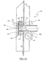
- An operating mechanism 190 constituted in FIG. 6 of a crank winch is assembled against the inner face of the cheek 100.
- This operating mechanism 190 comprises a dog clutch 192 provided central accommodation 194.
- the dog clutch 192 is designed to be housed in a nozzle mounted on the roller shutter axis to allow the rotational drive of said shutter axis roller around which the roller shutter curtain is wound.
- the roller shutter axis and the apron are not shown.
- the central housing 194 can be crossed by the endpiece shaft 180 during the housing the first shaped end 182 of the tip shaft 180 in the housing of polygonal section 150 to allow centering of the mechanism maneuver 190 with respect to the internal face of the cheek 100, as appears in the Fig. 2.
- the operating mechanism 190 also includes a means fixing 196 such as one or more screws 196 in this Fig., and which is intended to immobilize the orientation of the operating mechanism 190 relative to the face internal cheek piece 100 at the desired angle of connection to the knee cap fitted its crank (75 ° or 90 °).
- the screws two in number in this Fig., are housed respectively in holes made on either side of a bearing the operating axis of the crank winch and are screwed into reservations 122 provided in the inner face of the cheek 100.
- the operating axis of the crank winch is positioned at this Fig. at an angle of 75 ° to the vertical axis of the cheek 100.
- these reservations 122 are arranged in an arc around the housing 130, which makes it possible to position the same operating mechanism 190 in a different angular position, or allowing the angular positioning of another type of operating mechanism 190 against the inner face of the cheek 100.
- the second shaped end of the endpiece shaft is mounted telescopically to the end piece.
- This second shaped end of the tip shaft can receive a load compensation mechanism, not shown, and intended to reduce the operating torque during training in rotation of the deck by the operating mechanism.
- the second shaped end of the tip shaft is assembled to his respective cheek in the same way as the first end 182 is with cheek 100.
- a sleeve 140 as shown in Figs. 13a, 13b, 13c in each housing 130 of a cheek 100, so that the step 168 of the second elastic finger 164 can be housed in the groove 136 of said housing 130 for allow the clipping of the sleeve 140 in said housing 130.
- the notches 146 then overlap the notches 132 respectively, which ensures a blocking in rotation of the sleeve 140 in its housing 130.
- the first shaped end 182 of the tip shaft 180 mounted at through an operating mechanism 190, is housed in the section housing polygonal 150 of sleeve 140 as shown in Figs. 13a, 13b, 13c.
- the first shaped end 182 is oriented so that the lug 156 of the sleeve 140 can be housed in the orifice 184 made in said end shaped 182.
- the first shaped end 182 is linked mechanically with the sleeve 140, and therefore with the cheek 100 of a shutter device D.
- the second shaped end of the tip shaft is assembled to his cheek respective in the same way as the first shaped end 182 is with the plays 100.
- the operating mechanism 190 is then positioned in rotation and then fixed on the internal face of the cheek 100 by the fixing means 196.
- roller shutter deck is then fixed to the axis by deck ties whose end opposite the deck is designed to fit into a reservation provided on the axle tube.
- the assembly of the components of the roller shutter in a tunnel-safe permitted by the shutter device according to the invention is made by manual assembly and does not require no use of tools, except a screwdriver for the installation of one or two fixing means 196 of the winch mechanism.
- a second embodiment of the assembly of a roller shutter with a winch type operating mechanism 190a in a following tunnel safe the invention is described below with the components of a second manufacturer of accessories B.
- the particularity resides in the fact that the end piece of the flap axis rolling on the mechanism side behaves like a hub which, after having passed through said mechanism, fits on a trunnion.
- an insert 186a is housed in a sleeve 140 mounted in the housing 130 of a cheek 100.
- the insert 186a consists of a journal 187a provided for lodge in the first end of a roller shutter axle end not shown at Fig. 8.
- this pin 187a is extended coaxially by a square section pin 188a, also shown in FIG. 9b and whose dimension allows it to be housed in the housing of polygonal section 150 of the sleeve 140 shown in Figs. 9c and 9d.
- a groove 189a is produced at the periphery of the spindle 188a. This groove 189a is intended to receive the lug 156 of the first elastic finger 152 of a sleeve 140, as shown in FIG. 9c.
- a second step it is possible to mount the assembly constituted by the insert 186a and the sleeve 140 shown in Figs. 4a and 4b in housing 130 of one of the two cheeks 100 of the shutter devices of the tunnel safe to be equipped and a sleeve 140, comprising a housing of polygonal cross section 150 and of cross section square in the housing 130 of the other cheek 100.
- the end piece provided with its winch-type mechanism 190a, is fitted on pin 187a of insert 186a.
- the 180g telescopic tip shaft square section of the roller shutter axis which is visible only in Fig. 10 is engaged in the square section housing 150 of the sleeve 140, until the lug 156 is housed in the orifice 184 produced in the end of said endpiece shaft. Then the 180g telescopic tip shaft is immobilized in extension by a ring of tightening to prevent dislocation of the end piece fitted in the mechanism winch type operation 190a.
- the winch-type operating mechanism 190a is then oriented in the desired angle, then immobilized on the internal face of the cheek 100 by means of fixing 196.
- the two sleeves 140 comprising respectively a housing 150 of square section are used, either on the mechanism side maneuver, either side opposite to the winch type operating mechanism 190a.
- the assembly of the components of the roller shutter, from a second manufacturer of accessories B, in a tunnel safe enabled by the shutter device according to the invention is made by manual assembly and does not require the use of tools, except a screwdriver for the installation of the fixing mechanism of the winch type operation 190a.
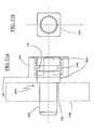
- This 186b insert has the distinction of having a 188b section pin square, the shoulder 179b of which protrudes from the sleeve 140, when it is mounted in this one.
- This arrangement makes it possible to offset the operating mechanism 190b of the type belt pulley mounted on a journal 187b of said cheek insert 186b 100 shown in thin lines in FIG. 11a.
- the assembly consisting of: the insert 186b and the sleeve 140 in each housing 130 of the two cheeks 100 of the shuttering devices of the tunnel safe to be fitted, in the same way as was previously described.
- the roller shutter axis is fitted at each of its ends with a nozzle, for example fully retractable type.
- the pulley with strap of the actuating mechanism 190b of the pulley type with strap fits on the head of the nozzle.
- Each end piece fits onto the pin 187b of the insert 186b by being retracted from the axis of a stroke limited by the shoulder 179b on said tip.
- the roller shutter deck is put in place as in the first example.
- the assembly of the components of the roller shutter, of a third manufacturer of accessories C, in a tunnel safe, enabled by the shutter device according to the invention is done by manual assembly and does not require the use tooling.
- a fourth example of mounting a roller shutter, with motor electric, in a tunnel safe according to the invention is described below with the constituents of a fourth manufacturer E.
- a motor support 192c is fixed by clipping to a sleeve 140c.
- the sleeve 140c comprises, in FIG. 12c, at least one accommodation of polygonal section 142c formed in protrusion of a shoulder 144c, and which is intended to allow centering and positioning in rotation of an opening of polygonal section 194c formed on the motor support 192c.
- Fig. 12a the external face of the shoulder 144c is positioned in the same plane that the internal face of the cheek 100 shown in fine lines.
- the housing of polygonal section 142c has at least one slot longitudinal in which is arranged an elastic tab 146c provided with a step 148c capable of clipping the polygonal section opening 194c, as this is also visible in FIG. 13a.
- the motor support 192c can be secured by clipping on the sleeve 140c.
- the operating mechanism of which is an electric motor in a tunnel safe, it is first necessary to fit in the housing 130 of the cheek of the shutter device, the sleeve 140c provided with the motor support 192c. Side opposite to the operating mechanism, a sleeve 140 having a concave square or polygonal shaped housing quadrilobe is clipped on the cheek 100 depending on whether a tip shaft is used shaped telescopic or a square telescopic end cap shaft.
- roller shutter axis fitted at one end with its electrical mechanism and at the other end of its telescopic tip shaft is put in place.
- the motor head is fitted and clipped into the motor support 192c and the tip shaft is fitted and clipped into the sleeve 140c.
- roller shutter curtain is put in place as in the examples precedents.
- the assembly of the components of the roller shutter of a fourth manufacturer of accessories in a tunnel safe is made by manual assembly, without the use of tools.
- exemplary embodiments of a rolling shutter assembly in a tunnel safe can be considered, especially those relating to different commercial tip tree shapes.
Landscapes
- Engineering & Computer Science (AREA)
- Structural Engineering (AREA)
- Architecture (AREA)
- Civil Engineering (AREA)
- Operating, Guiding And Securing Of Roll- Type Closing Members (AREA)
- Spinning Or Twisting Of Yarns (AREA)
- Finishing Walls (AREA)
- Rollers For Roller Conveyors For Transfer (AREA)
- Extrusion Moulding Of Plastics Or The Like (AREA)
- Excavating Of Shafts Or Tunnels (AREA)
- Power-Operated Mechanisms For Wings (AREA)
- Filling Or Emptying Of Bunkers, Hoppers, And Tanks (AREA)
- Package Closures (AREA)
- Processing Of Meat And Fish (AREA)
Claims (9)
- Endverschlusskappe (D) zum Verschließen eines Seitenendes (402, 404) eines Rollladenkastens (400), wobei die Endverschlusskappe (D) insbesondere aus einem Seitenstück (100) besteht, dass mit einem Absatz (300) verbunden ist,
dadurch gekennzeichnet, dass
das Seitenstück (100) eine erste Aufnahme (130) umfasst, die als Ausbeulung des Seitenstücks (100) gebildet ist und dazu gedacht ist, einen Stutzen (140, 140c) aufzunehmen, der eine zweite Aufnahme (150, 142c) umfasst, die es ermöglicht, ein angepasstes Ende (182) einer Rollladen-Ansatzachse (180) oder einer Spindel (188a, 188b) eines Einsatzes (186a, 186b) oder einen Motorhalter (192c) aufzunehmen. - Endverschlusskappe (D) nach Anspruch 1, dadurch gekennzeichnet, dass die erste Aufnahme (130) zylindrisch ist und mindestens eine Rippung (132) umfasst, die länglich und reliefartig auf der Innenwand der ersten Aufnahme (130) gebildet ist, wobei es die Rippung (132) ermöglicht, jeweils eine Kerbe (146) zu überlappen, die auf dem Mantel (142) des Stutzens (140, 140c) gebildet ist, um die drehmäßige Positionierung des Stutzens (140, 140c) in der ersten Aufnahme (130) zu ermöglichen.
- Endverschlusskappe (D) nach Anspruch 1 oder 2, dadurch gekennzeichnet, dass die erste Aufnahme (130) eine Rinne (136) umfasst, die neben dem Boden (138) der ersten Aufnahme (130) liegt und es ermöglicht, eine Stufe (168) aufzunehmen, die auf einer Nocke (166) gebildet ist, die am Ende eines elastischen Stifts (164) angeordnet ist, der in einem Ausschnitt gebildet ist, der in einer Kerbe (146) des Mantels (142) des Stutzens (140, 140c) ausgebildet ist, um den Stutzen (140, 140c) translationsmäßig in der ersten Aufnahme (130) zu blockieren.
- Endverschlusskappe (D) nach Anspruch 3, dadurch gekennzeichnet, dass der Stutzen (140, 140c) einen Verankerungspunkt (172) umfasst, der auf der Nocke (166) gebildet ist und es einem Werkzeug, das durch eine Öffnung (170) gegangen ist, die durch eine Schulter (144, 144c) des Stutzens (140, 140c) ausgebildet ist, ermöglicht, den elastischen Stift (164) zu verformen, indem es auf den Verankerungspunkt (172) einwirkt, um die Stufe (168) aus der Rinne (136) zu holen und die Entnahme des Stutzens (140, 140c) aus der ersten Aufnahme (130) zu ermöglichen.
- Endverschlusskappe (D) nach Anspruch 4, dessen Seitenstück (100) eine Grundplatte (120) umfasst, dadurch gekennzeichnet, dass ein Schacht (170a) in der Grundplatte (120) ausgebildet ist, wobei der Schacht (170a) einerseits in die Innenseite des Seitenstücks (100) und andererseits in das Innere der ersten Aufnahme (130) einmündet, um die Einführung eines Werkzeugs in die erste Aufnahme (130) zu ermöglichen, um auf den Verankerungspunkt (172) einzuwirken.
- Endverschlusskappe (D) nach einem der vorhergehenden Ansprüche, dadurch gekennzeichnet, dass der Stutzen (140) eine Nocke (156) umfasst, die mit einer Stufe (158) versehen ist, die auf einem elastischen Stift (152) gebildet ist, der in einem Ausschnitt gebildet ist, der durch eine Seite (154) der zweiten Aufnahme (150) ausgebildet ist und es der Stufe (158) ermöglicht, in einer Öffnung (184) oder einer Rinne (189a, 189b) aufgenommen zu werden, die jeweils in dem angepassten Ende (182) oder dem Einsatz (186a, 186b) ausgebildet sind, um jeweils in Axialrichtung die Ansatzachse (180) oder den Einsatz (186a, 186b) in der zweiten Aufnahme (150) des Stutzens (140) durch Einklemmen zu blockieren.
- Endverschlusskappe (D) nach Anspruch 6, dadurch gekennzeichnet, dass der Stutzen (140, 140c) einen Verankerungspunkt (162) umfasst, der an dem freien Ende des elastischen Stifts (152) gebildet ist und es einem Werkzeug, das durch eine Öffnung (160) gegangen ist, die durch die Schulter (144, 144c) ausgebildet ist, ermöglicht, den elastischen Stift (152) zu verformen, um den Nocken (156) aus der Öffnung (184) herauszuholen, um die Entnahme der Ansatzachse (180) oder des Einsatzes (186a, 186b) aus dem Stutzen (140) zu ermöglichen.
- Endverschlusskappe (D) nach einem der vorhergehenden Ansprüche, dadurch gekennzeichnet, dass die zweite Aufnahme (150) eine Aufnahme mit vieleckigem, quadratischem Querschnitt ist.
- Endverschlusskappe (D) nach einem der Ansprüche 1 bis 7, dadurch gekennzeichnet, dass die zweite Aufnahme (150) eine Aufnahme mit konkavem vieleckigen Querschnitt in Form eines vierblättrigen Kleeblattes ist.
Priority Applications (1)
| Application Number | Priority Date | Filing Date | Title |
|---|---|---|---|
| DE60101496T DE60101496T3 (de) | 2000-04-18 | 2001-04-11 | Endverschlusskappe für Rolladenkasten |
Applications Claiming Priority (2)
| Application Number | Priority Date | Filing Date | Title |
|---|---|---|---|
| FR0004958A FR2807786B1 (fr) | 2000-04-18 | 2000-04-18 | Dispositif obturateur pour coffre-tunnel pour volet roulant |
| FR0004958 | 2000-04-18 |
Publications (3)
| Publication Number | Publication Date |
|---|---|
| EP1148205A1 EP1148205A1 (de) | 2001-10-24 |
| EP1148205B1 true EP1148205B1 (de) | 2003-12-17 |
| EP1148205B3 EP1148205B3 (de) | 2011-01-12 |
Family
ID=8849357
Family Applications (1)
| Application Number | Title | Priority Date | Filing Date |
|---|---|---|---|
| EP01460024A Expired - Lifetime EP1148205B3 (de) | 2000-04-18 | 2001-04-11 | Endverschlusskappe für Rolladenkasten |
Country Status (6)
| Country | Link |
|---|---|
| EP (1) | EP1148205B3 (de) |
| AT (1) | ATE256815T1 (de) |
| DE (1) | DE60101496T3 (de) |
| ES (1) | ES2210113T7 (de) |
| FR (1) | FR2807786B1 (de) |
| PT (1) | PT1148205E (de) |
Families Citing this family (2)
| Publication number | Priority date | Publication date | Assignee | Title |
|---|---|---|---|---|
| FR2865235B1 (fr) | 2004-01-16 | 2006-04-28 | Ms Dev | Joue pour un dispositif obturateur de coffre-tunnel |
| FR2877689B1 (fr) * | 2004-11-10 | 2008-08-15 | Zurfluh Feller Sa | Dispositif obturateur pour coffre de volet roulant, avec un systeme polyvalent de support et/ou fixation des axe et dispositif de manoeuvre du volet roulant |
Family Cites Families (3)
| Publication number | Priority date | Publication date | Assignee | Title |
|---|---|---|---|---|
| ES2081785T3 (es) * | 1994-02-18 | 1997-06-16 | Imbac Spa | Soporte mejorado para elementos de maniobra de persianas enrollables. |
| DE9409619U1 (de) * | 1994-06-17 | 1994-09-22 | Pax Gmbh | Rolladen-Kasten |
| FR2731037B1 (fr) * | 1995-02-27 | 1997-05-16 | Plumer Sa | Dispositif de montage d'un tube enrouleur, notamment d'un volet roulant |
-
2000
- 2000-04-18 FR FR0004958A patent/FR2807786B1/fr not_active Expired - Fee Related
-
2001
- 2001-04-11 EP EP01460024A patent/EP1148205B3/de not_active Expired - Lifetime
- 2001-04-11 PT PT01460024T patent/PT1148205E/pt unknown
- 2001-04-11 ES ES01460024T patent/ES2210113T7/es active Active
- 2001-04-11 AT AT01460024T patent/ATE256815T1/de active
- 2001-04-11 DE DE60101496T patent/DE60101496T3/de not_active Expired - Lifetime
Also Published As
| Publication number | Publication date |
|---|---|
| EP1148205A1 (de) | 2001-10-24 |
| PT1148205E (pt) | 2004-04-30 |
| FR2807786A1 (fr) | 2001-10-19 |
| EP1148205B3 (de) | 2011-01-12 |
| DE60101496T2 (de) | 2004-10-28 |
| DE60101496D1 (de) | 2004-01-29 |
| DE60101496T3 (de) | 2011-08-18 |
| ATE256815T1 (de) | 2004-01-15 |
| ES2210113T7 (es) | 2012-03-16 |
| FR2807786B1 (fr) | 2002-05-31 |
| ES2210113T3 (es) | 2004-07-01 |
Similar Documents
| Publication | Publication Date | Title |
|---|---|---|
| EP1568844B1 (de) | Endverschlusskappe eines Rolladenkastens | |
| EP0479719A1 (de) | Aufrolleinrichtung mit rohrförmigem Motor für Stores, Jalousien oder dergleichen | |
| EP1106751B1 (de) | Flexible Hecke für Schwimmbäder | |
| EP0672815B1 (de) | Befestigungsvorrichtung für Rolladen | |
| EP1148205B1 (de) | Endverschlusskappe für Rolladenkasten | |
| EP0468925B1 (de) | Vorrichtung zur Befestigung eines Rohrmotors für den Antrieb eines Vorhanges oder dergleichen einer Gebäudeöffnung | |
| EP1977070B1 (de) | Stützvorrichtung für rollo und mit solch einer vorrichtung zu versehene rolloanordnung | |
| EP1607568A1 (de) | Halter einer Wickelwelle und entsprechender Vorhang oder Sonnenschutz | |
| EP1035297A1 (de) | Rolladenkasten, Seitenteil und Abdeckprofil für den Kasten | |
| EP1300538B1 (de) | Endverschlusskappe für einen Rolladenkasten | |
| EP1571287B1 (de) | Rolladen zum Schutz einer Öffnung, insbesondere eines Fensters, einer Tür oder dergleichen | |
| EP0735228B1 (de) | Konsole für Befestigungsvorrichtung für Rolladen oder dergleichen | |
| FR2991369A1 (fr) | Dispositif modulaire de recouvrement d'un joint | |
| EP1114911B1 (de) | Endverschlusskappe für Rolladenkasten | |
| EP2304155B1 (de) | Haltevorrichtung für winde oder motor eines rollladens in einem aufrollgehäuse, winde und gehäuse mit derartiger vorrichtung | |
| FR2853928A1 (fr) | Dispositif de fixation d'un mecanisme de volet roulant dans une reservation d'une embrasure | |
| EP0701039A1 (de) | Vorrichtung zur Regulierung der Spannung einer Gardinen-Aufwickelvorrichtung | |
| FR2808556A1 (fr) | Guide-lame de volet roulant | |
| FR2877689A1 (fr) | Dispositif obturateur pour coffre de volet roulant, avec un systeme polyvalent de support et/ou fixation des axe et dispositif de manoeuvre du volet roulant | |
| EP1114914B1 (de) | Endverschlusskappe für Rolladenkasten | |
| EP1120533B1 (de) | Vorrichtung zur elektrischen Verbindung eines Rolladenkastens, Kasten und Rolladen mit einer derartigen Vorrichtung | |
| EP1262627B1 (de) | Flanschplatte für Rolladenkasten | |
| EP1022427A1 (de) | Rolladenbaueinheit für Tür, Fenster oder dergleichen | |
| EP1503030B1 (de) | Verkleidungsvorrichtung für einen Rollladen | |
| CA1274420A (fr) | Dispositif adaptable au cadre d'une fenetre |
Legal Events
| Date | Code | Title | Description |
|---|---|---|---|
| PUAI | Public reference made under article 153(3) epc to a published international application that has entered the european phase |
Free format text: ORIGINAL CODE: 0009012 |
|
| AK | Designated contracting states |
Kind code of ref document: A1 Designated state(s): AT BE CH CY DE DK ES FI FR GB GR IE IT LI LU MC NL PT SE TR |
|
| AX | Request for extension of the european patent |
Free format text: AL;LT;LV;MK;RO;SI |
|
| 17P | Request for examination filed |
Effective date: 20011119 |
|
| AKX | Designation fees paid |
Free format text: AT BE CH CY DE DK ES FI FR GB GR IE IT LI LU MC NL PT SE TR |
|
| 17Q | First examination report despatched |
Effective date: 20021022 |
|
| 111L | Licence recorded |
Free format text: 20021108 0100 ETABLISSEMENTS ZURFLUH FELLER, SOCIETE ANONYME |
|
| GRAH | Despatch of communication of intention to grant a patent |
Free format text: ORIGINAL CODE: EPIDOS IGRA |
|
| GRAS | Grant fee paid |
Free format text: ORIGINAL CODE: EPIDOSNIGR3 |
|
| GRAA | (expected) grant |
Free format text: ORIGINAL CODE: 0009210 |
|
| AK | Designated contracting states |
Kind code of ref document: B1 Designated state(s): AT BE CH CY DE DK ES FI FR GB GR IE IT LI LU MC NL PT SE TR |
|
| PG25 | Lapsed in a contracting state [announced via postgrant information from national office to epo] |
Ref country code: CY Free format text: LAPSE BECAUSE OF FAILURE TO SUBMIT A TRANSLATION OF THE DESCRIPTION OR TO PAY THE FEE WITHIN THE PRESCRIBED TIME-LIMIT Effective date: 20031217 Ref country code: FI Free format text: LAPSE BECAUSE OF FAILURE TO SUBMIT A TRANSLATION OF THE DESCRIPTION OR TO PAY THE FEE WITHIN THE PRESCRIBED TIME-LIMIT Effective date: 20031217 Ref country code: GB Free format text: LAPSE BECAUSE OF FAILURE TO SUBMIT A TRANSLATION OF THE DESCRIPTION OR TO PAY THE FEE WITHIN THE PRESCRIBED TIME-LIMIT Effective date: 20031217 Ref country code: IE Free format text: LAPSE BECAUSE OF FAILURE TO SUBMIT A TRANSLATION OF THE DESCRIPTION OR TO PAY THE FEE WITHIN THE PRESCRIBED TIME-LIMIT Effective date: 20031217 Ref country code: TR Free format text: LAPSE BECAUSE OF FAILURE TO SUBMIT A TRANSLATION OF THE DESCRIPTION OR TO PAY THE FEE WITHIN THE PRESCRIBED TIME-LIMIT Effective date: 20031217 Ref country code: NL Free format text: LAPSE BECAUSE OF FAILURE TO SUBMIT A TRANSLATION OF THE DESCRIPTION OR TO PAY THE FEE WITHIN THE PRESCRIBED TIME-LIMIT Effective date: 20031217 |
|
| REG | Reference to a national code |
Ref country code: GB Ref legal event code: FG4D Free format text: NOT ENGLISH |
|
| REG | Reference to a national code |
Ref country code: CH Ref legal event code: EP |
|
| REG | Reference to a national code |
Ref country code: CH Ref legal event code: NV Representative=s name: RIEDERER HASLER & PARTNER PATENTANWAELTE AG |
|
| REG | Reference to a national code |
Ref country code: IE Ref legal event code: FG4D Free format text: FRENCH |
|
| REF | Corresponds to: |
Ref document number: 60101496 Country of ref document: DE Date of ref document: 20040129 Kind code of ref document: P |
|
| PG25 | Lapsed in a contracting state [announced via postgrant information from national office to epo] |
Ref country code: GR Free format text: LAPSE BECAUSE OF FAILURE TO SUBMIT A TRANSLATION OF THE DESCRIPTION OR TO PAY THE FEE WITHIN THE PRESCRIBED TIME-LIMIT Effective date: 20040317 Ref country code: DK Free format text: LAPSE BECAUSE OF FAILURE TO SUBMIT A TRANSLATION OF THE DESCRIPTION OR TO PAY THE FEE WITHIN THE PRESCRIBED TIME-LIMIT Effective date: 20040317 Ref country code: SE Free format text: LAPSE BECAUSE OF FAILURE TO SUBMIT A TRANSLATION OF THE DESCRIPTION OR TO PAY THE FEE WITHIN THE PRESCRIBED TIME-LIMIT Effective date: 20040317 |
|
| PG25 | Lapsed in a contracting state [announced via postgrant information from national office to epo] |
Ref country code: MC Free format text: LAPSE BECAUSE OF NON-PAYMENT OF DUE FEES Effective date: 20040430 |
|
| REG | Reference to a national code |
Ref country code: PT Ref legal event code: SC4A Free format text: AVAILABILITY OF NATIONAL TRANSLATION Effective date: 20040209 |
|
| NLV1 | Nl: lapsed or annulled due to failure to fulfill the requirements of art. 29p and 29m of the patents act | ||
| GBV | Gb: ep patent (uk) treated as always having been void in accordance with gb section 77(7)/1977 [no translation filed] |
Effective date: 20031217 |
|
| REG | Reference to a national code |
Ref country code: ES Ref legal event code: FG2A Ref document number: 2210113 Country of ref document: ES Kind code of ref document: T3 |
|
| REG | Reference to a national code |
Ref country code: IE Ref legal event code: FD4D |
|
| PLBE | No opposition filed within time limit |
Free format text: ORIGINAL CODE: 0009261 |
|
| 26N | No opposition filed |
Effective date: 20040920 |
|
| REG | Reference to a national code |
Ref country code: FR Ref legal event code: CD Ref country code: FR Ref legal event code: CJ Ref country code: FR Ref legal event code: CL |
|
| REG | Reference to a national code |
Ref country code: FR Ref legal event code: CA Ref country code: FR Ref legal event code: CL |
|
| PLCP | Request for limitation filed |
Free format text: ORIGINAL CODE: EPIDOSNLIM1 |
|
| PLCQ | Request for limitation of patent found admissible |
Free format text: ORIGINAL CODE: 0009231 |
|
| LIM1 | Request for limitation found admissible |
Free format text: SEQUENCE NO: 1; FILED AFTER OPPOSITION PERIOD Filing date: 20091109 |
|
| PLCR | Communication despatched that request for limitation of patent was allowed |
Free format text: ORIGINAL CODE: 0009245 |
|
| REG | Reference to a national code |
Ref country code: DE Ref legal event code: 8505 |
|
| PLCN | Payment of fee for limitation of patent |
Free format text: ORIGINAL CODE: EPIDOSNRAL3 |
|
| PUAM | (expected) publication of b3 document |
Free format text: ORIGINAL CODE: 0009410 |
|
| STAA | Information on the status of an ep patent application or granted ep patent |
Free format text: STATUS: THE PATENT HAS BEEN LIMITED |
|
| REG | Reference to a national code |
Ref country code: CH Ref legal event code: AEN Free format text: REQUETE DE LIMITATION ACCORDEE |
|
| REG | Reference to a national code |
Ref country code: CH Ref legal event code: NV Representative=s name: RIEDERER HASLER & PARTNER PATENTANWAELTE AG |
|
| PGFP | Annual fee paid to national office [announced via postgrant information from national office to epo] |
Ref country code: LU Payment date: 20110429 Year of fee payment: 11 |
|
| PGFP | Annual fee paid to national office [announced via postgrant information from national office to epo] |
Ref country code: CH Payment date: 20110428 Year of fee payment: 11 |
|
| PGFP | Annual fee paid to national office [announced via postgrant information from national office to epo] |
Ref country code: AT Payment date: 20110414 Year of fee payment: 11 |
|
| REG | Reference to a national code |
Ref country code: CH Ref legal event code: PL |
|
| REG | Reference to a national code |
Ref country code: AT Ref legal event code: MM01 Ref document number: 256815 Country of ref document: AT Kind code of ref document: T Effective date: 20120411 |
|
| PG25 | Lapsed in a contracting state [announced via postgrant information from national office to epo] |
Ref country code: LI Free format text: LAPSE BECAUSE OF NON-PAYMENT OF DUE FEES Effective date: 20120430 Ref country code: CH Free format text: LAPSE BECAUSE OF NON-PAYMENT OF DUE FEES Effective date: 20120430 Ref country code: AT Free format text: LAPSE BECAUSE OF NON-PAYMENT OF DUE FEES Effective date: 20120411 |
|
| PGFP | Annual fee paid to national office [announced via postgrant information from national office to epo] |
Ref country code: PT Payment date: 20130410 Year of fee payment: 13 |
|
| PG25 | Lapsed in a contracting state [announced via postgrant information from national office to epo] |
Ref country code: LU Free format text: LAPSE BECAUSE OF NON-PAYMENT OF DUE FEES Effective date: 20120411 |
|
| PGFP | Annual fee paid to national office [announced via postgrant information from national office to epo] |
Ref country code: IT Payment date: 20140430 Year of fee payment: 14 Ref country code: DE Payment date: 20140418 Year of fee payment: 14 Ref country code: ES Payment date: 20140428 Year of fee payment: 14 |
|
| PGFP | Annual fee paid to national office [announced via postgrant information from national office to epo] |
Ref country code: BE Payment date: 20140418 Year of fee payment: 14 |
|
| REG | Reference to a national code |
Ref country code: PT Ref legal event code: MM4A Free format text: LAPSE DUE TO NON-PAYMENT OF FEES Effective date: 20141013 |
|
| PG25 | Lapsed in a contracting state [announced via postgrant information from national office to epo] |
Ref country code: PT Free format text: LAPSE BECAUSE OF NON-PAYMENT OF DUE FEES Effective date: 20141013 |
|
| REG | Reference to a national code |
Ref country code: FR Ref legal event code: TP Owner name: ZURFLUH FELLER, FR Effective date: 20150119 |
|
| REG | Reference to a national code |
Ref country code: FR Ref legal event code: PLFP Year of fee payment: 15 |
|
| REG | Reference to a national code |
Ref country code: DE Ref legal event code: R119 Ref document number: 60101496 Country of ref document: DE |
|
| PG25 | Lapsed in a contracting state [announced via postgrant information from national office to epo] |
Ref country code: DE Free format text: LAPSE BECAUSE OF NON-PAYMENT OF DUE FEES Effective date: 20151103 Ref country code: IT Free format text: LAPSE BECAUSE OF NON-PAYMENT OF DUE FEES Effective date: 20150411 |
|
| REG | Reference to a national code |
Ref country code: CH Ref legal event code: PK Free format text: LA DATE CORRECTE DE LA LIMITATION REQUISE EST 09.11.2009 Ref country code: CH Ref legal event code: AELM Ref country code: CH Ref legal event code: PK Free format text: LA DATE CORRECTE DE LA REQUETE DE LIMITIATION ACCORDEE EST 12.01.2011 |
|
| REG | Reference to a national code |
Ref country code: ES Ref legal event code: FD2A Effective date: 20160526 |
|
| REG | Reference to a national code |
Ref country code: FR Ref legal event code: PLFP Year of fee payment: 16 |
|
| PG25 | Lapsed in a contracting state [announced via postgrant information from national office to epo] |
Ref country code: ES Free format text: LAPSE BECAUSE OF NON-PAYMENT OF DUE FEES Effective date: 20150412 |
|
| REG | Reference to a national code |
Ref country code: FR Ref legal event code: PLFP Year of fee payment: 17 |
|
| PG25 | Lapsed in a contracting state [announced via postgrant information from national office to epo] |
Ref country code: BE Free format text: LAPSE BECAUSE OF NON-PAYMENT OF DUE FEES Effective date: 20150430 |
|
| REG | Reference to a national code |
Ref country code: FR Ref legal event code: PLFP Year of fee payment: 18 |
|
| PGFP | Annual fee paid to national office [announced via postgrant information from national office to epo] |
Ref country code: FR Payment date: 20200313 Year of fee payment: 20 |