EP1147956A2 - Reinigungsanlage für Scheiben - Google Patents
Reinigungsanlage für Scheiben Download PDFInfo
- Publication number
- EP1147956A2 EP1147956A2 EP01108346A EP01108346A EP1147956A2 EP 1147956 A2 EP1147956 A2 EP 1147956A2 EP 01108346 A EP01108346 A EP 01108346A EP 01108346 A EP01108346 A EP 01108346A EP 1147956 A2 EP1147956 A2 EP 1147956A2
- Authority
- EP
- European Patent Office
- Prior art keywords
- actuating piston
- sealing element
- cleaning system
- actuating
- piston
- Prior art date
- Legal status (The legal status is an assumption and is not a legal conclusion. Google has not performed a legal analysis and makes no representation as to the accuracy of the status listed.)
- Withdrawn
Links
Images


Classifications
-
- F—MECHANICAL ENGINEERING; LIGHTING; HEATING; WEAPONS; BLASTING
- F15—FLUID-PRESSURE ACTUATORS; HYDRAULICS OR PNEUMATICS IN GENERAL
- F15B—SYSTEMS ACTING BY MEANS OF FLUIDS IN GENERAL; FLUID-PRESSURE ACTUATORS, e.g. SERVOMOTORS; DETAILS OF FLUID-PRESSURE SYSTEMS, NOT OTHERWISE PROVIDED FOR
- F15B13/00—Details of servomotor systems ; Valves for servomotor systems
- F15B13/02—Fluid distribution or supply devices characterised by their adaptation to the control of servomotors
- F15B13/04—Fluid distribution or supply devices characterised by their adaptation to the control of servomotors for use with a single servomotor
- F15B13/0401—Valve members; Fluid interconnections therefor
- F15B13/0405—Valve members; Fluid interconnections therefor for seat valves, i.e. poppet valves
-
- B—PERFORMING OPERATIONS; TRANSPORTING
- B05—SPRAYING OR ATOMISING IN GENERAL; APPLYING FLUENT MATERIALS TO SURFACES, IN GENERAL
- B05B—SPRAYING APPARATUS; ATOMISING APPARATUS; NOZZLES
- B05B12/00—Arrangements for controlling delivery; Arrangements for controlling the spray area
- B05B12/02—Arrangements for controlling delivery; Arrangements for controlling the spray area for controlling time, or sequence, of delivery
- B05B12/04—Arrangements for controlling delivery; Arrangements for controlling the spray area for controlling time, or sequence, of delivery for sequential operation or multiple outlets
-
- B—PERFORMING OPERATIONS; TRANSPORTING
- B05—SPRAYING OR ATOMISING IN GENERAL; APPLYING FLUENT MATERIALS TO SURFACES, IN GENERAL
- B05B—SPRAYING APPARATUS; ATOMISING APPARATUS; NOZZLES
- B05B12/00—Arrangements for controlling delivery; Arrangements for controlling the spray area
- B05B12/02—Arrangements for controlling delivery; Arrangements for controlling the spray area for controlling time, or sequence, of delivery
- B05B12/06—Arrangements for controlling delivery; Arrangements for controlling the spray area for controlling time, or sequence, of delivery for effecting pulsating flow
-
- B—PERFORMING OPERATIONS; TRANSPORTING
- B60—VEHICLES IN GENERAL
- B60S—SERVICING, CLEANING, REPAIRING, SUPPORTING, LIFTING, OR MANOEUVRING OF VEHICLES, NOT OTHERWISE PROVIDED FOR
- B60S1/00—Cleaning of vehicles
- B60S1/02—Cleaning windscreens, windows or optical devices
- B60S1/46—Cleaning windscreens, windows or optical devices using liquid; Windscreen washers
- B60S1/48—Liquid supply therefor
- B60S1/481—Liquid supply therefor the operation of at least part of the liquid supply being controlled by electric means
-
- B—PERFORMING OPERATIONS; TRANSPORTING
- B60—VEHICLES IN GENERAL
- B60S—SERVICING, CLEANING, REPAIRING, SUPPORTING, LIFTING, OR MANOEUVRING OF VEHICLES, NOT OTHERWISE PROVIDED FOR
- B60S1/00—Cleaning of vehicles
- B60S1/02—Cleaning windscreens, windows or optical devices
- B60S1/56—Cleaning windscreens, windows or optical devices specially adapted for cleaning other parts or devices than front windows or windscreens
- B60S1/60—Cleaning windscreens, windows or optical devices specially adapted for cleaning other parts or devices than front windows or windscreens for signalling devices, e.g. reflectors
- B60S1/603—Cleaning windscreens, windows or optical devices specially adapted for cleaning other parts or devices than front windows or windscreens for signalling devices, e.g. reflectors the operation of at least a part of the cleaning means being controlled by electric means
Definitions
- the invention relates to a cleaning system for windows, in particular Headlamp panes for motor vehicles, with a pump for conveying a cleaning liquid to at least two each in the area of the discs arranged nozzles and with one inlet and at least two Valves having outlets, the axially movable in a cylinder Has actuating piston, which cooperates with a spring, the spring force counteracts movement of the actuating piston as a result of actuation of the pump.
- EP 0 782 946 B1 describes a cleaning system for panes with a Valve known that a single-acting cylinder with an actuating piston provides that moved against a spring force when pressurized becomes.
- the control piston is connected to a piston rod, which is in a separate Space of the valve has an opening so that it moves axially the piston rod successively at least two outlets of the valve sweeps over.
- the outlets are each connected to lines that lead to different Guide nozzles assigned to a headlight.
- the cleaning liquid conveyed to the inlet by means of a pump time-shifted to the windows of the headlights.
- To Switching off the pump enables the spring energy stored in the return spring an automatic backward movement of the control piston in its Starting position.
- a disadvantage of the known cleaning system is that the valve is quite voluminous and is structurally complex. There are several pressure rooms and branched liquid channels necessary. A compensation choke is for Pressure equalization required when the actuating piston moves backwards. The valve also prevents cleaning fluid from flowing back when activated a telescopic arm carrying the nozzle by means of the cleaning liquid.
- the object of the present invention is therefore to provide a cleaning system for Develop slices in such a way that a quickly changing Control of nozzles is made possible.
- the invention is in connection with the preamble of claim 1, characterized in that a first actuating piston and a second actuating piston connected to one another via a coupling element are that a sealing element delimiting a pressure chamber is displaceable is mounted on the coupling element that the first and / or second actuating piston is supported against the sealing element by a spring element, that the inlet is arranged in such a region of the cylinder that when the cylinder is pressurized, an actuating force on the first and / or second actuating piston and the sealing element acts, and that with generating one the first actuating piston and / or the second actuating piston the spring element assigned to the first actuating piston and / or second actuating piston is so tense that it is after the actuation is not concerned acts on the sealing element with a tracking force that is smaller than that on the Sealing element acting force and directed opposite to the same is.
- the particular advantage of the invention is that one each Pressure chamber defining and delimiting the same sealing element is always preloaded is immovable and while the inlet is pressurized is arranged. In this way, a safe and relatively short funding path can be be made possible by the valve.
- the valve is only the displacement of an actuating piston, which none Influence the funding route.
- the actuating piston serves to build up a tracking force, which after completion the pressurization ensures that the sealing element has a different, occupies a second end position releasing the conveying path. Will be beneficial only after the pump has been switched off does the sealing element move, so that the Delivery path is independent of the pump pressure.
- control piston is one connecting coupling element designed as a piston rod, the two opposite actuating pistons are rigidly connected.
- the valve is compact and space-saving.
- valve can be designed to be particularly reliable his.
- two spring elements are provided, which extend to both sides of the sealing element and on the one hand the sealing element and on the other supported on the respective actuating piston are.
- one end position of the sealing element or the adjusting piston is one the spring elements in a tensioned and another spring element in relaxed state.
- the spring force of the tensioned spring element is smaller than the force of the cleaning fluid caused by the pump pressure.
- the sealing element is advantageously arranged between the two actuating pistons and passed through the piston rod.
- the valve thus has a special simple construction.
- the sealing element is in a middle one Spreading section of the cylinder arranged.
- the inlet is in an axial Distance to the outlets, with the central axis of the inlet is arranged between the central axes of the outlets. The travel path of the As a result, the sealing element can be kept small and symmetrical.
- the actuating pistons have a different one effective footprint on so that a start up of the valve even when the sealing element is not in the end position.
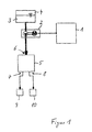
- Figure 1 is schematically a cleaning system for headlights of a motor vehicle shown, which essentially consists of a control unit 1, a pump 2, one serving as a reservoir for a cleaning liquid 3 Reservoir 4, a valve 5 downstream of the pump 2, which has an inlet 6 and two outlets 7 and 8, each at a different Headlights associated nozzle 9 and 10 are connected.
- a first Sealing element separating pressure chamber 11 from a second pressure chamber 12 13 on a first radial wall 14 of a central widening section 15 of the cylindrical valve 5 abut.
- the plate-shaped Sealing element 13 is coaxial with a coupling element designed as a piston rod 16 arranged.
- the sealing element 13 is longitudinally displaceable to the piston rod 16 arranged.
- the piston rod 16 has a first end a large adjusting piston 17 and one at an opposite end small adjusting piston 18.
- the outer diameters of the actuating pistons 17 and 18 correspond essentially to the inner diameter of the corresponding cylinder sections 19 and 20.
- Between the large actuating piston 17 and the A first spring element 21 is arranged in the sealing element 13.
- Between the small adjusting piston 18 and the sealing element 13 is a second spring element 22 arranged.
- the spring elements 21 and 22 are designed as coil springs.
- the spring element 21 is in a substantially relaxed state Status.
- the spring element 22 is essentially in one tense state.
- the actuating pistons 17 and 18 are in the first rest position according to the figure 2 is a fixed end position. The tight fit is achieved by a frictional The actuating pistons 17 and 18 bear against the inner lateral surfaces of the cylinder sections 19 or 20 allows.
- the control pistons 17 and 18 each plate-shaped edge webs 23 with a circumferential Press the edge against the inside of the cylinder sections 19, 20.
- the spring elements 21 and 22 are designed such that the Sealing element 13 by the spring element lying in the activated conveying path 21, 22 against the corresponding first radial wall 14 or against a second radial wall 24 is pressed.
- the first spring element 21 is slightly tensioned, so that the applied spring force for a clear positioning of the sealing element 13 cares.
- the pump 2 is switched on, so that according to Figure 3, the inlet 6 predetermined with a cleaning liquid Pressure is applied.
- the sealing element 13 becomes even stronger against the first radial wall 14 pressed.
- the cleaning liquid is removed by the second outlet 8 directed towards the nozzle 10.
- the second pressure chamber 12 is axially displaced by the small actuating piston 18 to in a closed adjustment range of the cylinder section 20.
- the large adjusting piston 17 is moved in the same direction, whereby the first spring element 21 is compressed and the second spring element 22 is stretched becomes.
- the generated by the compression of the first spring element 21 Spring force is less than that in the second pressure chamber 12 on the sealing element 13 acting holding force.
- the sealing element 13 is immovable in the first working position.
- the sealing element 13 through the in the first spring element 21 stored spring energy in the direction of the small adjusting piston 18, until the sealing element 13 on a second radial wall 24 of the middle Distribution section 15 comes to rest, see Figure 4.
- the first spring element 21 can still be tensioned.
- the frictional contact of the Edge webs 23 of the large and / or small adjusting pistons 17, 18 on the inner surfaces of the cylinder sections 19, 20 is selected such that the first spring element 21 is still excited to apply the corresponding holding force of the sealing element 13 on the second radial wall 24.
- the end position is always changed after pump 2 is switched off of the sealing element 13.
- the nozzles 9, 10 alternately with a cleaning liquid.
- the inlet 6 and the outlets 7, 8 are arranged axially offset from one another, the central axis of the inlet 6 between the central axes of the outlets 7 and 8 is arranged.
- the sealing element 13 is arranged in a plate shape and has in an outer edge region a in the axial direction sealing lips 25 on the the respective radial walls 14, 24 comes to rest.
- the middle widening section 15 of the cylinder in which the sealing element 13 is mounted has a smaller axial extent than the travel of Adjusting pistons 17, 18. If the sealing element 13 as a relatively thin membrane is formed, the middle widening section 15 can be further reduced be so that the cylinder can be made correspondingly shorter.
- the space between the actuating pistons 17, 18 and the end faces of each assigned cylinder sections 19, 20 can be filled with air, which via a Opening 26, 27 can be exchanged with the environment.
- the end faces of the cylinder could also be closed and the space between the actuating pistons 17, 18 on the one hand and the end faces the respective assigned cylinder sections 19, 20 on the other hand with liquid be filled.
- the piston rod 16 has an axial bore provided for pressure equalization.
Landscapes
- Engineering & Computer Science (AREA)
- Mechanical Engineering (AREA)
- Physics & Mathematics (AREA)
- Fluid Mechanics (AREA)
- General Engineering & Computer Science (AREA)
- Water Supply & Treatment (AREA)
- Nozzles (AREA)
- Cleaning By Liquid Or Steam (AREA)
Abstract
Description
- Figur 1
- ein Blockschaltbild einer erfindungsgemäßen Reinigungsanlage,
- Figur 2
- ein schematischer Längsschnitt durch ein erfindungsgemäßes Ventil in einer ersten Ruheposition,
- Figur 3
- ein schematischer Längsschnitt durch das Ventil in einer ersten Ar- beitsposition,
- Figur 4
- ein schematischer Längsschnitt durch das Ventil in einer zweiten Ruheposition und
- Figur 5
- ein schematischer Längsschnitt durch das Ventil in einer zweiten Arbeitsposition.
Claims (12)
- Reinigungsanlage für Scheiben, insbesondere für Scheiben von Scheinwerfern für Kraftfahrzeuge, mit einer Pumpe zum Fördern einer Reinigungsflüssigkeit zu mindestens zwei jeweils im Bereich der Scheiben angeordneten Düsen und mit einem einen Einlass und mindestens zwei Auslässe aufweisenden Ventil, das in einem Zylinder einen axialbeweglichen Stellkolben aufweist, der mit einer Feder zusammenwirkt, dessen Federkraft einer Bewegung des Stellkolbens in Folge der Betätigung der Pumpe entgegenwirkt, dadurch gekennzeichnet, dass ein erster Stellkolben (17) und ein zweiter Stellkolben (18) über ein Koppelelement (16) miteinander verbunden sind, dass ein einen Druckraum (11, 12) begrenzendes Dichtelement (13) verschieblich zu dem Koppelelement (16) gelagert ist, dass der erste und/oder zweite Stellkolben (17, 18) jeweils über ein Federelement (21, 22) gegenüber dem Dichtelement (13) abgestützt ist, dass der Einlass (6) in einem solchen Bereich des Zylinders angeordnet ist, dass bei Druckbeaufschlagung des Zylinders eine Stellkraft auf den ersten und/oder zweiten Stellkolben (17, 18) und das Dichtelement (13) wirkt, und dass mit Erzeugen einer den ersten Stellkolben (17) und/oder zweiten Stellkolben (18) verschiebende Stellkraft das den ersten Stellkolben (17) und/oder zweiten Stellkolben (18) zugeordnete Federelement (21, 22) derart gespannt wird, dass es nach dem Nichtanliegen der Stellkraft auf das Dichtelement (13) mit einer Nachführkraft wirkt, die kleiner als die auf das Dichtelement (13) wirkende Stellkraft und entgegengesetzt zu derselben gerichtet ist.
- Reinigungsanlage nach Anspruch 1, dadurch gekennzeichnet, dass das Koppelelement als Kolbenstange (16) ausgebildet ist, die den ersten Stellkolben (17) mit dem zweiten Stellkolben (18) starr miteinander verbindet.
- Reinigungsanlage nach Anspruch 1 oder 2, dadurch gekennzeichnet, dass der erste Stellkolben (17) und/oder der zweiten Stellkolben (18) reibschlüssig in einem Zylinderabschnitt (19, 20) gelagert sind, wobei die Reibkraft derart hoch ist, dass das in dem den Förderweg freigebenden Druckraum (11, 12) befindliche Federelement (21, 22) abgestützt ist zum Festlegen des Dichtelementes (13) in einer Endlage.
- Reinigungsanlage nach einem der Ansprüche 1 bis 3, dadurch gekennzeichnet, dass das Dichtelement (13) in axialer Richtung zwischen dem ersten Stellkolben (17) und dem zweiten Stellkolben (18) koaxial verschiebbar ist.
- Reinigungsanlage nach einem der Ansprüche 1 bis 4, dadurch gekennzeichnet, dass das Dichtelement (13) tellerförmig ausgebildet ist und mit jeder Druckbeaufschlagung wechselweise mit einem Außenrandbereich an einer Innenwandung eines Verbreiterungsabschnitts (15) des Zylinders angedrückt ist.
- Reinigungsanlage nach einem der Ansprüche 1 bis 5, dadurch gekennzeichnet, dass der Einlass (6) und die Auslässe (7, 8) parallel zueinander verlaufen, wobei die Auslässe (7, 8) in einem gleichen axialen Abstand zu dem Einlass (6) angeordnet sind.
- Reinigungsanlage nach einem der Ansprüche 1 bis 6, dadurch gekennzeichnet, dass der erste Stellkolben (17) und der zweite Stellkolben (18) jeweils tellerförmig mit nach außen abgeschrägten Randstegen (23) ausgebildet sind zur reibschlüssigen Anlage an den Innenwandungen der Zylinderabschnitte (19, 20).
- Reinigungsanlage nach einem der Ansprüche 1 bis 7, dadurch gekennzeichnet, dass während der Druckbeaufschlagung das jeweils in einem geschlossenen Druckraum (11, 12) befindliche Federelement (21, 22) gestaucht und dass das jeweils in einem offenen Druckraum (11, 12) befindliche zweite Federelement (21, 22) entspannt ausgebildet ist.
- Reinigungsanlage nach einem der Ansprüche 1 bis 8, dadurch gekennzeichnet, dass das Dichtelement (13) als Membran ausgebildet ist.
- Reinigungsanlage nach einem der Ansprüche 1 bis 9, dadurch gekennzeichnet, dass die Stellkolben (17, 18) eine unterschiedliche große wirksame Stellfläche aufweisen.
- Reinigungsanlage nach einem der Ansprüche 1 bis 10, dadurch gekennzeichnet, dass der Druckausgleich zwischen den durch die Stellkolben (17, 18) einerseits und den Stirnflächen der Zylinderabschnitten (19, 20) andererseits über eine Verbindung mit der Umgebung oder mittels einer hohl ausgebildeten Kolbenstange (16) erfolgt.
- Reinigungsanlage nach einem der Ansprüche 1 bis 11, dadurch gekennzeichnet, dass die Federelemente (21, 22) in der äußeren Endlage durch einen Morsekegel, Saugnäpfe, Magneten oder durch mechanische Verrastung abgestützt sind.
Applications Claiming Priority (2)
| Application Number | Priority Date | Filing Date | Title |
|---|---|---|---|
| DE10019283 | 2000-04-19 | ||
| DE10019283A DE10019283A1 (de) | 2000-04-19 | 2000-04-19 | Reinigungsanlage für Scheiben |
Publications (2)
| Publication Number | Publication Date |
|---|---|
| EP1147956A2 true EP1147956A2 (de) | 2001-10-24 |
| EP1147956A3 EP1147956A3 (de) | 2003-08-20 |
Family
ID=7639236
Family Applications (1)
| Application Number | Title | Priority Date | Filing Date |
|---|---|---|---|
| EP01108346A Withdrawn EP1147956A3 (de) | 2000-04-19 | 2001-04-03 | Reinigungsanlage für Scheiben |
Country Status (2)
| Country | Link |
|---|---|
| EP (1) | EP1147956A3 (de) |
| DE (1) | DE10019283A1 (de) |
Cited By (8)
| Publication number | Priority date | Publication date | Assignee | Title |
|---|---|---|---|---|
| WO2003095277A1 (en) * | 2002-05-08 | 2003-11-20 | Fico Transpar, S.A. | Cleaning system for headlamps of motor vehicles |
| WO2004012968A1 (de) * | 2002-07-31 | 2004-02-12 | Valeo Wischersysteme Gmbh | Steuerventil, düsenanordnung und waschanlage |
| EP1884426A3 (de) * | 2006-08-02 | 2008-11-19 | Hella KG Hueck & Co. | Reinigungsanlage für Scheiben |
| CN103707850A (zh) * | 2014-01-09 | 2014-04-09 | 任强 | 单刮片电磁换向同步刷洗雨刮器 |
| WO2016095865A1 (zh) * | 2014-12-19 | 2016-06-23 | 郑州三华科技实业有限公司 | 一种既大量注出又微量注出色浆泵 |
| WO2017220584A1 (en) * | 2016-06-20 | 2017-12-28 | Kautex Textron Gmbh & Co. Kg | Pressure operated manifold for a vehicle wash system |
| AT520109A1 (de) * | 2017-07-11 | 2019-01-15 | Avl List Gmbh | Reversible Pumpe |
| USD1103531S1 (en) * | 2025-03-25 | 2025-11-25 | Shenzhen Dushi Jinkang E-Commerce Company Ltd. | Under car cleaner |
Citations (1)
| Publication number | Priority date | Publication date | Assignee | Title |
|---|---|---|---|---|
| EP0782946B1 (de) | 1996-01-08 | 1999-12-08 | Mannesmann VDO AG | Scheibenreinigungsanlage |
Family Cites Families (5)
| Publication number | Priority date | Publication date | Assignee | Title |
|---|---|---|---|---|
| US4026468A (en) * | 1975-08-14 | 1977-05-31 | Mccord Corporation | Headlamp cleaning assembly |
| IT1169423B (it) * | 1983-05-26 | 1987-05-27 | Luciano Migliori | Valvola distributrice per circuiti pneumatici |
| JPS62261693A (ja) * | 1986-04-30 | 1987-11-13 | Maruko Keihouki Kk | 選択型送出ポンプ |
| US4858828A (en) * | 1986-09-15 | 1989-08-22 | Stachowiak J Edward | Multi-gun control valve |
| DE3708327A1 (de) * | 1987-03-14 | 1988-09-22 | Bosch Gmbh Robert | Einrichtung zum foerdern von fluessigkeit auf zwei ueber spritzduesen zu netzende, mit abstand voneinander angeordnete scheibenbereiche eines kraftfahrzeugs |
-
2000
- 2000-04-19 DE DE10019283A patent/DE10019283A1/de not_active Withdrawn
-
2001
- 2001-04-03 EP EP01108346A patent/EP1147956A3/de not_active Withdrawn
Patent Citations (1)
| Publication number | Priority date | Publication date | Assignee | Title |
|---|---|---|---|---|
| EP0782946B1 (de) | 1996-01-08 | 1999-12-08 | Mannesmann VDO AG | Scheibenreinigungsanlage |
Cited By (14)
| Publication number | Priority date | Publication date | Assignee | Title |
|---|---|---|---|---|
| WO2003095277A1 (en) * | 2002-05-08 | 2003-11-20 | Fico Transpar, S.A. | Cleaning system for headlamps of motor vehicles |
| US7753287B2 (en) | 2002-05-08 | 2010-07-13 | Fico Cables, S.A. | Cleaning system for headlamps of motor vehicles |
| WO2004012968A1 (de) * | 2002-07-31 | 2004-02-12 | Valeo Wischersysteme Gmbh | Steuerventil, düsenanordnung und waschanlage |
| CN100377937C (zh) * | 2002-07-31 | 2008-04-02 | 瓦莱奥擦拭系统有限公司 | 控制阀、喷嘴装置和清洗设备 |
| EP1884426A3 (de) * | 2006-08-02 | 2008-11-19 | Hella KG Hueck & Co. | Reinigungsanlage für Scheiben |
| CN103707850B (zh) * | 2014-01-09 | 2015-08-26 | 任强 | 单刮片电磁换向同步刷洗雨刮器 |
| CN103707850A (zh) * | 2014-01-09 | 2014-04-09 | 任强 | 单刮片电磁换向同步刷洗雨刮器 |
| WO2016095865A1 (zh) * | 2014-12-19 | 2016-06-23 | 郑州三华科技实业有限公司 | 一种既大量注出又微量注出色浆泵 |
| RU2692169C2 (ru) * | 2014-12-19 | 2019-06-21 | ЧЖЭНЧЖОУ САНЬХУА ТЕКНОЛОДЖИ энд ИНДАСТРИ КО., ЛТД | Насос, способный дозировать как большой объем, так и малый объем красителя |
| US10533543B2 (en) | 2014-12-19 | 2020-01-14 | Zhengzhou Sanhua Technology & Industry Co., Ltd | Pump capable of dispensing both a large volume and a small volume of colorant |
| WO2017220584A1 (en) * | 2016-06-20 | 2017-12-28 | Kautex Textron Gmbh & Co. Kg | Pressure operated manifold for a vehicle wash system |
| AT520109A1 (de) * | 2017-07-11 | 2019-01-15 | Avl List Gmbh | Reversible Pumpe |
| AT520109B1 (de) * | 2017-07-11 | 2019-09-15 | Avl List Gmbh | Reversible Pumpe |
| USD1103531S1 (en) * | 2025-03-25 | 2025-11-25 | Shenzhen Dushi Jinkang E-Commerce Company Ltd. | Under car cleaner |
Also Published As
| Publication number | Publication date |
|---|---|
| DE10019283A1 (de) | 2001-11-22 |
| EP1147956A3 (de) | 2003-08-20 |
Similar Documents
| Publication | Publication Date | Title |
|---|---|---|
| DE2725740C2 (de) | Steuerventilanordnung für eine druckmittelbetriebene Stellvorrichtung | |
| DE68906851T2 (de) | Hydraulisches pilotventil. | |
| DE2718776C2 (de) | Mit einem ersten Druckmittel betätigte Vorrichtung zur Erhöhung des Druckes eines zweiten Druckmittels in zwei Stufen | |
| DE102016107794A1 (de) | Strömungsdurchgangsschalteinheit | |
| EP0066274B1 (de) | Ventilanordnung zur Erhöhung der Ausfahrgeschwindigkeit eines Arbeitszylinders | |
| DE102021110042B4 (de) | Hydrauliksystem und Verfahren zum Betreiben eines Hydrauliksystems | |
| DE69902193T2 (de) | Ein Vierwege-Wählventil | |
| DE2525397B2 (de) | ||
| EP0274559B1 (de) | Schmierstoff-Injektor und Vorrichtung zur Schmierung von wandernden Schmierstellen | |
| DE10019283A1 (de) | Reinigungsanlage für Scheiben | |
| DE112018007603B4 (de) | Aktuator und Betätigungs- und Schmiermittelversorgungssystem für ein Kraftfahrzeug | |
| DE2237557B2 (de) | Kombinierter Druckmittel- und Federspeicherbremszylinder fur Kraftfahrzeuge | |
| DE2624013C2 (de) | Rohr- oder Schlauchleitungskupplung | |
| DE4031885A1 (de) | Magnetventil | |
| DE102006035938B4 (de) | Getriebestellvorrichtung mit einem Stellzylinder | |
| DE2925885A1 (de) | Pneumatischer tuerzylinder | |
| EP1130293A2 (de) | Steuereinrichtung für automatisierte Schaltgetriebe von Fahrzeugen, vorzugsweise von Kraftfahrzeugen | |
| DE2339529A1 (de) | Kraftstoffeinspritzpumpenverstellvorrichtung | |
| DE2909685A1 (de) | Hydraulischer kraftverstaerker | |
| WO2019219960A2 (de) | Zylinderanordnung | |
| EP1884426B1 (de) | Reinigungsanlage für Scheiben | |
| DE10215701A1 (de) | Messerhalter mit pneumatischer Schnittkrafteinstellung | |
| DE19851444B4 (de) | Ausbauvorrichtung für die äußere, als Werkzeugabstützung dienende Führungsbuchse im Gehäuse eines Schlagwerks | |
| DE3781779T2 (de) | Membran-bremszylinder fuer kraftfahrzeuge. | |
| DE3744795C2 (en) | Lubricant injector for chain conveyor roller bearings |
Legal Events
| Date | Code | Title | Description |
|---|---|---|---|
| PUAI | Public reference made under article 153(3) epc to a published international application that has entered the european phase |
Free format text: ORIGINAL CODE: 0009012 |
|
| AK | Designated contracting states |
Kind code of ref document: A2 Designated state(s): AT BE CH CY DE DK ES FI FR GB GR IE IT LI LU MC NL PT SE TR |
|
| AX | Request for extension of the european patent |
Free format text: AL;LT;LV;MK;RO;SI |
|
| PUAL | Search report despatched |
Free format text: ORIGINAL CODE: 0009013 |
|
| AK | Designated contracting states |
Designated state(s): AT BE CH CY DE DK ES FI FR GB GR IE IT LI LU MC NL PT SE TR |
|
| AX | Request for extension of the european patent |
Extension state: AL LT LV MK RO SI |
|
| AKX | Designation fees paid | ||
| REG | Reference to a national code |
Ref country code: DE Ref legal event code: 8566 |
|
| STAA | Information on the status of an ep patent application or granted ep patent |
Free format text: STATUS: THE APPLICATION IS DEEMED TO BE WITHDRAWN |
|
| 18D | Application deemed to be withdrawn |
Effective date: 20040221 |