EP1147926A2 - Verkürzungselement für eine Reifenkette - Google Patents
Verkürzungselement für eine Reifenkette Download PDFInfo
- Publication number
- EP1147926A2 EP1147926A2 EP01108144A EP01108144A EP1147926A2 EP 1147926 A2 EP1147926 A2 EP 1147926A2 EP 01108144 A EP01108144 A EP 01108144A EP 01108144 A EP01108144 A EP 01108144A EP 1147926 A2 EP1147926 A2 EP 1147926A2
- Authority
- EP
- European Patent Office
- Prior art keywords
- chain
- shortening
- shortening element
- length
- tire
- Prior art date
- Legal status (The legal status is an assumption and is not a legal conclusion. Google has not performed a legal analysis and makes no representation as to the accuracy of the status listed.)
- Granted
Links
Images
Classifications
-
- B—PERFORMING OPERATIONS; TRANSPORTING
- B60—VEHICLES IN GENERAL
- B60C—VEHICLE TYRES; TYRE INFLATION; TYRE CHANGING; CONNECTING VALVES TO INFLATABLE ELASTIC BODIES IN GENERAL; DEVICES OR ARRANGEMENTS RELATED TO TYRES
- B60C27/00—Non-skid devices temporarily attachable to resilient tyres or resiliently-tyred wheels
- B60C27/06—Non-skid devices temporarily attachable to resilient tyres or resiliently-tyred wheels extending over the complete circumference of the tread, e.g. made of chains or cables
- B60C27/10—Non-skid devices temporarily attachable to resilient tyres or resiliently-tyred wheels extending over the complete circumference of the tread, e.g. made of chains or cables having tensioning means
Definitions
- the present invention relates to a shortening element for a tire chain, in particular for a side chain, with a substantially C-shaped body, one of which opposite ends is designed essentially hook-shaped and at which this end has a support surface for a chain link.
- a generic shortening element is known for example from DE 197 48 940 C1. This known shortening element is held on one side and rotatably in a first chain link. In the unabridged state of the associated tire chain, there is a second chain link in one hooked free end of the shortening element. The shortening element is used to shorten the tire chain rotated by 180 ° with the second chain link attached. The free end of the Shortening element is hooked into another chain link, which is part of that Is chain strand, the end of which is formed by the first chain link.
- a first disadvantage of this known shortening element is that shortening the Chain is only possible in a single predetermined measure, namely by the length of the inner clear distance between the two ends of the shortening element.
- Another disadvantage results from the handling of the shortening element in the process of shortening the associated one Tire chain: As already explained, the shortening element is used for this purpose Rotated 180 °. Its free end is hung in another chain link. As from the Drawing of the above DE 197 48 940 C1 can be seen (see in particular Figure 4), wraps around this free end of the shortening element when it is hooked into the further chain link is the further chain link so far that it is the further chain link almost over half of it Length wraps around, but at least in the area of the curve at its end.
- the object of the present invention is therefore a generic shortening element to further develop that on the one hand it offers at least one shortening option and that on the other hand, the amount by which the tire chain has been shortened due to the shortening process is too loose on the tire, is as low as possible.
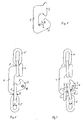
- Figure 1 shows the shortening element as such. It consists of a flat, essentially C-shaped base body 1 with two ends 2 and 3, which are opposite each other. The one end 2 is essentially hook-shaped.
- the other end 3 can be of any design be, e.g. either as shown in Figure 1, or as shown in the drawing to DE 197 48 940 C1 already mentioned. It is only important that one on this other end 3 suspended chain link 5 do not slip out of the shortening element can.
- One, hook-shaped end 2 of the shortening element points to its in a support surface 4 on the inner region of the surface facing the shortening element.
- This can either be flat or rounded to rounded (in the cross section of the shortening element considered) in order to be able to adapt approximately to the chain link (s) to be attached.
- the length L of this support surface 4 is at least twice the thickness D of the material the chain links 5 of the chain (shown in Figures 2 and 3).
- Figure 2 shows the shortening element according to the invention, linked to chain links 5 one Tire chain or a side chain, d. i.e., a side strand of a tire chain.
- the tire chain is not shortened.
- the last chain link 5 is a chain strand at the other end 3 of the shortening element hooked in such a way that this last Chain link 5 cannot slip off the other end 3.
- the last chain link 5 of another chain strand of the tire chain is attached. This represents the condition where the tire or side chain is not shortened.
- Shortening element is that a resulting free end of the other chain strand is free to move, can dangle and thus operate against the tire, on which the tire chain is mounted, or can hit against its rim or hub cap and can damage it. Such damage is in the invention Shortening element excluded, since the penultimate chain link 5, as can be seen from FIG. 3, outside on the hook-shaped end 2 of the shortening element and there from the shortening element and a fourth last link 5 of the other chain strand is held.
- Another advantage of the shortening element according to the invention over the previously known Shortening element consists in that, with a suitable design, the length L of the support surface 4 shortening of the shortening element according to the invention by any desired chain link is possible from the third to last chain link 5, while in the previously known shortening element such shortening only by two or a multiple of two chain links is possible because the known shortening element only shortens each when shortening Chain link can be hung, which is oriented perpendicular to the shortening element is. As is well known, this is only the case for every second chain link.
- an opening (6) can be seen in the area of one end 2.
- the opening 6 can be created by drilling or punching, for example.
- the breakthrough 6 is used for recording a locking element 7, which is indicated in Figure 3.
- the locking element 7 is intended to prevent the chain links 5 resting on the support surface 4 from slipping out.
- the Locking element 7 can either be made of elastic material, preferably with a length, which is only slightly larger than a clear width W of the chain links 5 Push chain links 5 over the locking element 7 with a certain amount of force to shorten or lengthen the tire chain.
- the locking element 7 can also be mechanically rigid in itself.
Landscapes
- Engineering & Computer Science (AREA)
- Mechanical Engineering (AREA)
- Hand Tools For Fitting Together And Separating, Or Other Hand Tools (AREA)
- Tires In General (AREA)
- Hooks, Suction Cups, And Attachment By Adhesive Means (AREA)
- Devices For Conveying Motion By Means Of Endless Flexible Members (AREA)
- Noodles (AREA)
Abstract
Description
- Figur 1
- das erfindungsgemäße Verkürzungselement als solches,
- Figur 2
- das erfindungsgemäße Verkürzungselement, eingehängt in eine Reifenkette, ohne diese zu verkürzen,
- Figur 3
- das erfindungsgemäße Verkürzungselement, eingehängt in eine Reifenkette unter Verkürzung derselben.
Claims (7)
- Verkürzungselement für eine Reifenkette, insbesondere für eine Seitenkette, mit einem im wesentlichen C-förmigen Grundkörper (1), bei dem eines (2) von sich gegenüberliegenden Enden (2, 3) des Grundkörpers (1) im Wesentlichen hakenförmig ausgelegt ist und bei dem dieses Ende (2) eine Stützfläche (4) aufweist für ein Kettenglied (5),
dadurch gekennzeichnet, dass die Stützfläche (4) eine Länge (L) aufweist, die wenigstens das 2-fache der Dicke (D) des Materials der Kettenglieder (5) beträgt. - Verkürzungselement nach Anspruch 1,
dadurch gekennzeichnet, dass das eine Ende (2) einen Durchbruch (6) aufweist zur Aufnahme eines Arretierungselements (7). - Verkürzungselement nach Anspruch 2,
dadurch gekennzeichnet, dass das Arretierungselement (7) elastisch ist. - Verkürzungselement nach Anspruch 3,
dadurch gekennzeichnet, dass das Arretierungselement (7) eine Länge aufweist, die geringfügig größer ist als die lichte Weite (W) der Kettenglieder (5). - Verkürzungselement nach Anspruch 2,
dadurch gekennzeichnet, dass das Arretierungselement (7) in sich mechanisch starr ist. - Verkürzungselement nach Anspruch 5,
dadurch gekennzeichnet, dass das Arretierungselement (7) eine Länge aufweist, die mindestens das 1 ½ -fache der lichten Weite (W) der Kettenglieder (5) beträgt. - Verkürzungselement nach einem der vorhergehenden Ansprüche,
dadurch gekennzeichnet, dass die Stützfläche (4) eine Länge (L) aufweist, die wenigstens das 3-fache der Dicke (D) des Materials der Kettenglieder (5) beträgt.
Applications Claiming Priority (2)
| Application Number | Priority Date | Filing Date | Title |
|---|---|---|---|
| DE10019802A DE10019802A1 (de) | 2000-04-20 | 2000-04-20 | Verkürzungselement |
| DE10019802 | 2000-04-20 |
Publications (3)
| Publication Number | Publication Date |
|---|---|
| EP1147926A2 true EP1147926A2 (de) | 2001-10-24 |
| EP1147926A3 EP1147926A3 (de) | 2003-02-05 |
| EP1147926B1 EP1147926B1 (de) | 2004-07-28 |
Family
ID=7639592
Family Applications (1)
| Application Number | Title | Priority Date | Filing Date |
|---|---|---|---|
| EP01108144A Expired - Lifetime EP1147926B1 (de) | 2000-04-20 | 2001-03-30 | Verkürzungselement für eine Reifenkette |
Country Status (3)
| Country | Link |
|---|---|
| EP (1) | EP1147926B1 (de) |
| AT (1) | ATE271979T1 (de) |
| DE (2) | DE10019802A1 (de) |
Citations (1)
| Publication number | Priority date | Publication date | Assignee | Title |
|---|---|---|---|---|
| DE19748940C1 (de) | 1997-10-24 | 1999-05-06 | Rud Ketten Rieger & Dietz | Verkürzungselement |
Family Cites Families (2)
| Publication number | Priority date | Publication date | Assignee | Title |
|---|---|---|---|---|
| DE1910077C3 (de) * | 1969-02-25 | 1978-11-23 | Rud-Kettenfabrik Rieger & Dietz Gmbh U. Co, 7080 Aalen | Kettenschloß |
| DE29719671U1 (de) * | 1997-10-24 | 1997-12-18 | Rud-Kettenfabrik Rieger & Dietz Gmbh U. Co, 73432 Aalen | Verschlußhaken |
-
2000
- 2000-04-20 DE DE10019802A patent/DE10019802A1/de not_active Withdrawn
-
2001
- 2001-03-30 AT AT01108144T patent/ATE271979T1/de not_active IP Right Cessation
- 2001-03-30 DE DE50102957T patent/DE50102957D1/de not_active Expired - Fee Related
- 2001-03-30 EP EP01108144A patent/EP1147926B1/de not_active Expired - Lifetime
Patent Citations (1)
| Publication number | Priority date | Publication date | Assignee | Title |
|---|---|---|---|---|
| DE19748940C1 (de) | 1997-10-24 | 1999-05-06 | Rud Ketten Rieger & Dietz | Verkürzungselement |
Also Published As
| Publication number | Publication date |
|---|---|
| DE50102957D1 (de) | 2004-09-02 |
| EP1147926B1 (de) | 2004-07-28 |
| DE10019802A1 (de) | 2001-10-25 |
| EP1147926A3 (de) | 2003-02-05 |
| ATE271979T1 (de) | 2004-08-15 |
Similar Documents
| Publication | Publication Date | Title |
|---|---|---|
| DE2356289C2 (de) | Laschenkette für Kegelscheibengetriebe | |
| DE4029842A1 (de) | Klemme | |
| DE1605670B2 (de) | Verbindungsglied fuer fahrzeugreifenketten | |
| EP0389831A2 (de) | Vorrichtung zum Binden langgestreckter Gegenstände | |
| EP1147926B1 (de) | Verkürzungselement für eine Reifenkette | |
| DE2851708B2 (de) | Verbindungsorgan für ein Lastgehänge | |
| DE1755529B2 (de) | Verbindungsglied fuer reifenketten | |
| DE202014105649U1 (de) | Anschlussvorrichtung für eine endseitige Verbindung einer Zugfeder | |
| DE2246841C2 (de) | Reifenkette, insbesondere Reifengleitschutzkette | |
| DE3326899C2 (de) | ||
| DE203213C (de) | ||
| DE3828523C2 (de) | ||
| DE19748940C1 (de) | Verkürzungselement | |
| EP0331069A1 (de) | Aufhängekopf für Anschlagmittel | |
| DE3308747A1 (de) | Sperrglied | |
| DE2804735C3 (de) | Endbeschlag für Lasthebe- und/oder Verzurrbänder | |
| AT413202B (de) | Stützglied zur verwendung bei einer reifenkette und reifenkette | |
| DE1505004B2 (de) | Stegglied für Reifenketten | |
| DE1683599C (de) | Aufwickelwalze aus Blech fur einen mit einem Gurt od dgl betatigbaren RoI laden | |
| DE2520332C3 (de) | Sicherheitshaken zum Einhängen von Ketten o.dgl., insbesondere zum Verbinden einer Anhängerkupplung für Kraftfahrzeuge oder auch zum Verbinden einer Kuhkette | |
| DE7607473U1 (de) | Abschleppstange für Kraftfahrzeuge | |
| DE2718181A1 (de) | Verbindungsglied fuer reifenketten | |
| AT389746B (de) | Federpuffer | |
| DE2166976C3 (de) | Anschlagbolzen für einen Abstandhalter | |
| CH619652A5 (en) | Chain, in particular for forming a side-chain strand of an anti-skid chain or tyre protection chain |
Legal Events
| Date | Code | Title | Description |
|---|---|---|---|
| PUAI | Public reference made under article 153(3) epc to a published international application that has entered the european phase |
Free format text: ORIGINAL CODE: 0009012 |
|
| AK | Designated contracting states |
Kind code of ref document: A2 Designated state(s): AT BE CH CY DE DK ES FI FR GB GR IE IT LI LU MC NL PT SE TR |
|
| AX | Request for extension of the european patent |
Free format text: AL;LT;LV;MK;RO;SI |
|
| PUAL | Search report despatched |
Free format text: ORIGINAL CODE: 0009013 |
|
| AK | Designated contracting states |
Designated state(s): AT BE CH CY DE DK ES FI FR GB GR IE IT LI LU MC NL PT SE TR |
|
| AX | Request for extension of the european patent |
Extension state: AL LT LV MK RO SI |
|
| RIC1 | Information provided on ipc code assigned before grant |
Ipc: 7B 60C 27/14 B Ipc: 7F 16G 15/04 B Ipc: 7B 60C 27/06 B Ipc: 7B 60C 27/10 A |
|
| 17P | Request for examination filed |
Effective date: 20030116 |
|
| 17Q | First examination report despatched |
Effective date: 20030318 |
|
| AKX | Designation fees paid |
Designated state(s): AT CH DE LI |
|
| GRAP | Despatch of communication of intention to grant a patent |
Free format text: ORIGINAL CODE: EPIDOSNIGR1 |
|
| GRAS | Grant fee paid |
Free format text: ORIGINAL CODE: EPIDOSNIGR3 |
|
| GRAA | (expected) grant |
Free format text: ORIGINAL CODE: 0009210 |
|
| AK | Designated contracting states |
Kind code of ref document: B1 Designated state(s): AT CH DE LI |
|
| REG | Reference to a national code |
Ref country code: CH Ref legal event code: EP |
|
| REG | Reference to a national code |
Ref country code: IE Ref legal event code: FG4D Free format text: GERMAN |
|
| REF | Corresponds to: |
Ref document number: 50102957 Country of ref document: DE Date of ref document: 20040902 Kind code of ref document: P |
|
| REG | Reference to a national code |
Ref country code: CH Ref legal event code: NV Representative=s name: ROTTMANN, ZIMMERMANN + PARTNER AG |
|
| PGFP | Annual fee paid to national office [announced via postgrant information from national office to epo] |
Ref country code: CH Payment date: 20050318 Year of fee payment: 5 |
|
| REG | Reference to a national code |
Ref country code: IE Ref legal event code: FD4D |
|
| PLBE | No opposition filed within time limit |
Free format text: ORIGINAL CODE: 0009261 |
|
| STAA | Information on the status of an ep patent application or granted ep patent |
Free format text: STATUS: NO OPPOSITION FILED WITHIN TIME LIMIT |
|
| 26N | No opposition filed |
Effective date: 20050429 |
|
| PG25 | Lapsed in a contracting state [announced via postgrant information from national office to epo] |
Ref country code: LI Free format text: LAPSE BECAUSE OF NON-PAYMENT OF DUE FEES Effective date: 20060331 Ref country code: CH Free format text: LAPSE BECAUSE OF NON-PAYMENT OF DUE FEES Effective date: 20060331 |
|
| REG | Reference to a national code |
Ref country code: CH Ref legal event code: PL |
|
| PGFP | Annual fee paid to national office [announced via postgrant information from national office to epo] |
Ref country code: AT Payment date: 20070313 Year of fee payment: 7 |
|
| PGFP | Annual fee paid to national office [announced via postgrant information from national office to epo] |
Ref country code: DE Payment date: 20070315 Year of fee payment: 7 |
|
| PG25 | Lapsed in a contracting state [announced via postgrant information from national office to epo] |
Ref country code: AT Free format text: LAPSE BECAUSE OF NON-PAYMENT OF DUE FEES Effective date: 20080330 |
|
| PG25 | Lapsed in a contracting state [announced via postgrant information from national office to epo] |
Ref country code: DE Free format text: LAPSE BECAUSE OF NON-PAYMENT OF DUE FEES Effective date: 20081001 |