EP1146217A2 - Schaltungsanordnung zum Betrieb eines hochdynamischen elektromagnetischen Hubanker-Aktors - Google Patents
Schaltungsanordnung zum Betrieb eines hochdynamischen elektromagnetischen Hubanker-Aktors Download PDFInfo
- Publication number
- EP1146217A2 EP1146217A2 EP01108705A EP01108705A EP1146217A2 EP 1146217 A2 EP1146217 A2 EP 1146217A2 EP 01108705 A EP01108705 A EP 01108705A EP 01108705 A EP01108705 A EP 01108705A EP 1146217 A2 EP1146217 A2 EP 1146217A2
- Authority
- EP
- European Patent Office
- Prior art keywords
- coil
- circuit arrangement
- transistors
- arrangement according
- current
- Prior art date
- Legal status (The legal status is an assumption and is not a legal conclusion. Google has not performed a legal analysis and makes no representation as to the accuracy of the status listed.)
- Withdrawn
Links
- 238000002485 combustion reaction Methods 0.000 claims description 4
- 238000010586 diagram Methods 0.000 description 8
- 230000000694 effects Effects 0.000 description 5
- 238000000926 separation method Methods 0.000 description 2
- 230000000903 blocking effect Effects 0.000 description 1
- 230000004907 flux Effects 0.000 description 1
- 230000006698 induction Effects 0.000 description 1
- 239000000696 magnetic material Substances 0.000 description 1
Images

Classifications
-
- F—MECHANICAL ENGINEERING; LIGHTING; HEATING; WEAPONS; BLASTING
- F02—COMBUSTION ENGINES; HOT-GAS OR COMBUSTION-PRODUCT ENGINE PLANTS
- F02D—CONTROLLING COMBUSTION ENGINES
- F02D41/00—Electrical control of supply of combustible mixture or its constituents
- F02D41/20—Output circuits, e.g. for controlling currents in command coils
-
- F—MECHANICAL ENGINEERING; LIGHTING; HEATING; WEAPONS; BLASTING
- F01—MACHINES OR ENGINES IN GENERAL; ENGINE PLANTS IN GENERAL; STEAM ENGINES
- F01L—CYCLICALLY OPERATING VALVES FOR MACHINES OR ENGINES
- F01L9/00—Valve-gear or valve arrangements actuated non-mechanically
- F01L9/20—Valve-gear or valve arrangements actuated non-mechanically by electric means
-
- F—MECHANICAL ENGINEERING; LIGHTING; HEATING; WEAPONS; BLASTING
- F02—COMBUSTION ENGINES; HOT-GAS OR COMBUSTION-PRODUCT ENGINE PLANTS
- F02D—CONTROLLING COMBUSTION ENGINES
- F02D13/00—Controlling the engine output power by varying inlet or exhaust valve operating characteristics, e.g. timing
- F02D13/02—Controlling the engine output power by varying inlet or exhaust valve operating characteristics, e.g. timing during engine operation
- F02D13/0253—Fully variable control of valve lift and timing using camless actuation systems such as hydraulic, pneumatic or electromagnetic actuators, e.g. solenoid valves
-
- F—MECHANICAL ENGINEERING; LIGHTING; HEATING; WEAPONS; BLASTING
- F02—COMBUSTION ENGINES; HOT-GAS OR COMBUSTION-PRODUCT ENGINE PLANTS
- F02D—CONTROLLING COMBUSTION ENGINES
- F02D41/00—Electrical control of supply of combustible mixture or its constituents
- F02D41/0002—Controlling intake air
- F02D2041/001—Controlling intake air for engines with variable valve actuation
-
- F—MECHANICAL ENGINEERING; LIGHTING; HEATING; WEAPONS; BLASTING
- F02—COMBUSTION ENGINES; HOT-GAS OR COMBUSTION-PRODUCT ENGINE PLANTS
- F02D—CONTROLLING COMBUSTION ENGINES
- F02D41/00—Electrical control of supply of combustible mixture or its constituents
- F02D41/20—Output circuits, e.g. for controlling currents in command coils
- F02D2041/2017—Output circuits, e.g. for controlling currents in command coils using means for creating a boost current or using reference switching
-
- F—MECHANICAL ENGINEERING; LIGHTING; HEATING; WEAPONS; BLASTING
- F02—COMBUSTION ENGINES; HOT-GAS OR COMBUSTION-PRODUCT ENGINE PLANTS
- F02D—CONTROLLING COMBUSTION ENGINES
- F02D41/00—Electrical control of supply of combustible mixture or its constituents
- F02D41/20—Output circuits, e.g. for controlling currents in command coils
- F02D2041/2068—Output circuits, e.g. for controlling currents in command coils characterised by the circuit design or special circuit elements
- F02D2041/2072—Bridge circuits, i.e. the load being placed in the diagonal of a bridge to be controlled in both directions
Definitions
- the invention relates to a circuit arrangement for operating a highly dynamic electromagnetic lifting armature actuator according to the preamble of the claim 1.
- An area of application for a highly dynamic electromagnetic lifting armature actuator is the electromagnetically actuated valve train of an internal combustion engine.
- Gas exchange globe valves are opened by such actuators in an oscillating manner and closed.
- the valve timing of the internal combustion engine can be chosen completely freely can be optimally adapted to an operating state.
- the electromagnetic lifting armature actuator there is an armature between two electromagnets arranged and is powered by a corresponding current Electromagnetic coils between the positions “lift valve open” and “Lift valve closed” moved back and forth. That from the lifting anchor actuator and the Springs existing system is a spring-mass vibration system.
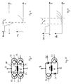
- Fig. 3 An embodiment of such a half-bridge circuit is shown in Fig. 3.
- a coil W at both ends via transistors T1 and T2, each with one pole of a supply voltage source connected.
- transistors T1 and T2 are turned on the coil W is supplied with current in a certain direction (see arrow in FIG. 3).
- the two diodes D1 and D2 form a so-called free-running branch, via which the current commutates automatically as soon as the transistors T1 and T2 turn off become. However, the current only flows in one direction the sink.
- a disadvantage is the detachment of the armature from the laminated core of the magnet by eddy currents and influences remanence flows in the magnetic material. These effects result to the fact that there are strong scattering in the peeling time. This effect is shown in Fig. 4. This shows that the anchor's trajectory changes turn off the power can develop differently. Each of the three in FIG. 4 curves shown represents a possible movement behavior. This scatter leads to the fact that control edges cannot be adhered to exactly, which leads to negative effects Influences in engine performance and engine torque or to increase consumption and leads to a reduction in efficiency.
- the object of the present invention is to provide a circuit arrangement with which the above disadvantages can be prevented.
- the or each coil of an electromagnetic actuator via at least two switching elements is connected to at least one supply voltage source, namely such that current can be passed through the coil in both directions.
- Transistors are particularly suitable as switching elements.
- a full bridge circuit is used in which the Coil at each end via a switching element with the supply voltage source and is connected to ground via another switching element.
- Corresponding switching of the switching elements can reverse the current in the coil become. This makes it possible, for example, to switch one off when the coil is switched off build up short current pulse in the opposite direction so that the remanence field strength can be brought to zero. A short current pulse in the opposite direction can also occur ensure a rapid reduction of eddy currents that otherwise would slowly fade away.
- a type of half-bridge circuit is included two supply voltage sources, namely + U and -U, are used, and via the Switching elements, the coil can optionally be connected to a voltage source become. The current flow through the coil can also be reversed in this way.
- a coil W is an electromagnetic one Actuator shown.
- One end of the coil W is connected to the supply voltage via a transistor T3 U and connected to ground via a transistor T4.
- the other The end of the coil W is also connected to the supply voltage via a transistor T5 U and in turn connected to ground via a transistor T6.
- each transistor T3 to T4 is connected to diodes D3 to D6 in parallel, whose mode of operation will be explained later.
- the diodes are D4 and D5 are provided, which serve as a freewheeling circuit.
- the coil W can be energized in another direction.
- the diodes D3 and D6 serve as a freewheeling circuit when the transistors T4 and T5 are blocked again.
- the magnetic interference effects can be reduced in such a way that the period T 2 , in which scattering occurs in the detachment time, is kept very small compared to a conventional circuit arrangement (cf. duration T 2 versus duration T 1 from FIG. 1).
- FIG. 5 Another embodiment of the invention is shown in FIG. 5.
- Coil W ' shown, which is connected to ground at one end.
- the other end the coil W ' is via a first transistor T7 with a positive supply voltage source (+ U) and with a second transistor T8 with a negative Supply voltage source -U connected.
- the two transistors T7 and T8 diodes D7 and D8 connected in parallel, which in turn as freewheeling diodes serve.
- circuit arrangements can also be used allow a reversal of the current flow in the coil of the highly dynamic actuator and thus to achieve precise control edges for the operation of an internal combustion engine contribute with electromagnetically operated gas exchange valves.
Landscapes
- Engineering & Computer Science (AREA)
- Mechanical Engineering (AREA)
- General Engineering & Computer Science (AREA)
- Chemical & Material Sciences (AREA)
- Combustion & Propulsion (AREA)
- Valve Device For Special Equipments (AREA)
- Reciprocating, Oscillating Or Vibrating Motors (AREA)
Abstract
Description
- Fig. 1
- ein Schaltbild einer Ausführungsform einer erfindungsgemäßen Schaltungsanordnung,
- Fig. 2
- zwei Diagramme, aus denen das Ablöseverhalten eines mit der erfindungsgemäßen Schaltungsanordnung betriebenen Aktors erkennbar ist,
- Fig. 3
- ein Schaltbild einer herkömmlichen Schaltungsanordnung,
- Fig. 4
- zwei Diagramme, aus denen das Ablöseverhalten eines mit der in Fig. 3 gezeigten Schaltungsanordnung betriebenen Aktors erkennbar ist und
- Fig. 5
- ein Schaltbild einer weiteren Ausführungsform einer erfindungsgemäßen Schaltungsanordnung.
Claims (6)
- Schaltungsanordnung zum Betrieb eines hochdynamischen elektromagnetischen Hubanker-Aktors für ein Gaswechsel-Ventil eines Verbrennungsmotors mit zumindest eine Spule, die einen Anker des elektromagnetischen Aktors bei deren Bestromung anzieht,
dadurch gekennzeichnet, dass die Spule derart über zumindest zwei Schaltelemente (T3-T8) mit zumindest einer Versorgungsspannungsquelle (+U, -U) verbunden ist, dass Strom in beiden Richtungen durch die Spule (W, W') geleitet werden kann. - Schaltungsanordnung nach Anspruch 1,
dadurch gekennzeichnet, daß als Schaltelemente Transistoren (T3-T8) verwendet sind. - Schaltungsanordnung nach Anspruch 1 oder 2,
dadurch gekennzeichnet, daß eine Vollbrückenschaltung mit vier Schaltelementen, insbesondere vier Transistoren (T3-T6), vorgesehen ist, wobei die Spule (W) an jedem Ende jeweils über ein Schaltelement (T3, T5) mit der Versorgungsspannungsquelle (+U) und über ein anderes Schaltelement (T4, T6) mit Masse verbunden ist. - Schaltungsanordnung nach Anspruch 3,
dadurch gekennzeichnet, daß zur Absicherung der Transistoren jeweils Dioden (D3-D6) parallelgeschaltet sind. - Schaltungsanordnung nach Anspruch 1 oder 2,
dadurch gekennzeichnet, dass ein Ende der Spule (W') mit Masse und das andere Ende der Spule über ein erstes Schaltelement (T7) mit einer positiven Versorgungsquelle (+U) und über ein zweites Schaltelement (T8) mit einer negativen Versorgungsquelle (-U) verbunden ist. - Schaltungsanordnung nach Anspruch 5,
dadurch gekennzeichnet, dass beide Schaltelemente als Transistoren (T7, T8) ausgeführt sind, welche durch parallelgeschaltete Dioden (D7, D8) abgesichert sind.
Applications Claiming Priority (2)
| Application Number | Priority Date | Filing Date | Title |
|---|---|---|---|
| DE10018175 | 2000-04-12 | ||
| DE10018175A DE10018175A1 (de) | 2000-04-12 | 2000-04-12 | Schaltungsanordnung zum Betrieb eines hochdynamischen elektromagnetischen Hubanker-Aktors |
Publications (2)
| Publication Number | Publication Date |
|---|---|
| EP1146217A2 true EP1146217A2 (de) | 2001-10-17 |
| EP1146217A3 EP1146217A3 (de) | 2003-03-19 |
Family
ID=7638502
Family Applications (1)
| Application Number | Title | Priority Date | Filing Date |
|---|---|---|---|
| EP01108705A Withdrawn EP1146217A3 (de) | 2000-04-12 | 2001-04-06 | Schaltungsanordnung zum Betrieb eines hochdynamischen elektromagnetischen Hubanker-Aktors |
Country Status (2)
| Country | Link |
|---|---|
| EP (1) | EP1146217A3 (de) |
| DE (1) | DE10018175A1 (de) |
Cited By (6)
| Publication number | Priority date | Publication date | Assignee | Title |
|---|---|---|---|---|
| FR2863119A1 (fr) * | 2003-11-28 | 2005-06-03 | Renault Sas | Dispositif et procede de commande d'un actionneur magnetostrictif. |
| US7187567B2 (en) | 2002-01-02 | 2007-03-06 | Bae Systems Plc | Operation of a current controller |
| EP1762708A3 (de) * | 2005-09-09 | 2007-09-26 | Toyota Jidosha Kabushiki Kaisha | Elektromagnetisch betätigtes Ventil and Regelverfahren dazu |
| US7348689B2 (en) | 2002-01-02 | 2008-03-25 | Bae Systems Plc | Switching circuit and a method of operation thereof |
| US7692337B2 (en) | 2002-01-02 | 2010-04-06 | Bae Systems Plc | Switching circuit and a method of operation thereof |
| US7832378B2 (en) | 2006-01-24 | 2010-11-16 | Continental Automotive Gmbh | Device for switching inductive fuel injection valves |
Families Citing this family (5)
| Publication number | Priority date | Publication date | Assignee | Title |
|---|---|---|---|---|
| DE10232741A1 (de) * | 2002-07-19 | 2004-02-05 | Ina-Schaeffler Kg | Treiberstufe für ein Solenoidventil |
| DE10232742A1 (de) * | 2002-07-19 | 2004-02-05 | Ina-Schaeffler Kg | Treiberstufe für ein Solenoidventil |
| DE10323172A1 (de) * | 2003-05-22 | 2004-12-09 | Ina-Schaeffler Kg | Treiberstufe für ein Solenoidventil |
| DE102006025360B3 (de) * | 2006-05-31 | 2007-10-31 | Siemens Ag | Vorrichtung zum Schalten induktiver Kraftstoff-Einspritzventile |
| DE102017011453B4 (de) | 2017-12-12 | 2024-10-24 | Thomas Magnete Gmbh | Elektromagnetische Vorrichtung zur gesteuerten Krafterzeugung und Verfahren zum Betrieb der Vorrichtung |
Family Cites Families (7)
| Publication number | Priority date | Publication date | Assignee | Title |
|---|---|---|---|---|
| DE3420611A1 (de) * | 1984-06-02 | 1985-12-05 | Robert Bosch Gmbh, 7000 Stuttgart | Einrichtung zur steuerung und regelung des stroms durch einen elektromagnetischen verbraucher in verbindung mit brennkraftmaschinen |
| DE3819593A1 (de) * | 1988-06-09 | 1989-12-14 | Vdo Schindling | Schaltungsanordnung fuer ein elektrisches stellglied |
| JP3134724B2 (ja) * | 1995-02-15 | 2001-02-13 | トヨタ自動車株式会社 | 内燃機関の弁駆動装置 |
| JPH09189209A (ja) * | 1996-01-08 | 1997-07-22 | Honda Motor Co Ltd | エンジンの電磁駆動バルブ制御装置 |
| JP3508407B2 (ja) * | 1996-08-01 | 2004-03-22 | 株式会社日立製作所 | 内燃機関用燃料噴射弁の駆動装置 |
| DE19747033A1 (de) * | 1997-10-24 | 1999-04-29 | Daimler Chrysler Ag | Elektronische Schalteinrichtung für Magneten |
| JP3550989B2 (ja) * | 1997-12-08 | 2004-08-04 | トヨタ自動車株式会社 | 電磁バルブ用駆動装置 |
-
2000
- 2000-04-12 DE DE10018175A patent/DE10018175A1/de not_active Withdrawn
-
2001
- 2001-04-06 EP EP01108705A patent/EP1146217A3/de not_active Withdrawn
Cited By (6)
| Publication number | Priority date | Publication date | Assignee | Title |
|---|---|---|---|---|
| US7187567B2 (en) | 2002-01-02 | 2007-03-06 | Bae Systems Plc | Operation of a current controller |
| US7348689B2 (en) | 2002-01-02 | 2008-03-25 | Bae Systems Plc | Switching circuit and a method of operation thereof |
| US7692337B2 (en) | 2002-01-02 | 2010-04-06 | Bae Systems Plc | Switching circuit and a method of operation thereof |
| FR2863119A1 (fr) * | 2003-11-28 | 2005-06-03 | Renault Sas | Dispositif et procede de commande d'un actionneur magnetostrictif. |
| EP1762708A3 (de) * | 2005-09-09 | 2007-09-26 | Toyota Jidosha Kabushiki Kaisha | Elektromagnetisch betätigtes Ventil and Regelverfahren dazu |
| US7832378B2 (en) | 2006-01-24 | 2010-11-16 | Continental Automotive Gmbh | Device for switching inductive fuel injection valves |
Also Published As
| Publication number | Publication date |
|---|---|
| DE10018175A1 (de) | 2001-10-25 |
| EP1146217A3 (de) | 2003-03-19 |
Similar Documents
| Publication | Publication Date | Title |
|---|---|---|
| DE19909305B4 (de) | Verfahren zur Ansteuerung eines elektromagnetischen Ventils zur Betätigung eines Motorventils | |
| DE602004010561T2 (de) | Elektromagnetischer Ventilaktuator mit einem Dauermagnet für eine Brennkraftmaschine | |
| EP1146217A2 (de) | Schaltungsanordnung zum Betrieb eines hochdynamischen elektromagnetischen Hubanker-Aktors | |
| DE10310448A1 (de) | Elektromagnetische Stellvorrichtung | |
| DE3242667T1 (de) | Schaltmagnet | |
| EP0405191A1 (de) | Elektromagnetisch arbeitende Stelleinrichtung | |
| DE10014113C2 (de) | Solenoid-Ventilantriebsvorrichtung | |
| EP0796503A1 (de) | Polarisiertes relais | |
| DE10341582B4 (de) | Schaltungsanordnung zum schnellen Schalten induktiver Lasten | |
| DE102009029826B4 (de) | Elektromagnetventil | |
| DE19529151A1 (de) | Verfahren zum Schalten eines elektromagnetischen Aktuators | |
| DE19712064A1 (de) | Elektromagnetischer Antrieb | |
| DE102006025397B4 (de) | Elektromagnetisch angetriebenes Ventil | |
| DE19714413A1 (de) | Elektromagnetischer Antrieb | |
| DE602005002752T2 (de) | Elektromagnetische steuervorrichtung für ein ventil einer brennkraftmaschine | |
| DE19712062A1 (de) | Elektromagnetische Stelleinrichtung | |
| EP2195565B1 (de) | Anordnung von angereihten magnetantrieben | |
| DE102004062340A1 (de) | Elektromagnetischer Antrieb mit Flußleitstücken | |
| AT518231B1 (de) | Gepoltes elektromechanisches Relais mit steuerbarer Leistungsaufnahme | |
| DE3206687A1 (de) | Hubmagnetantriebe mit den an die jeweiligen antriebserfordernisse angepassten kennlinien | |
| DE69903991T2 (de) | Ultraschneller Elektromagnetantrieb ohne Feder | |
| DE3614528A1 (de) | Verfahren zum betreiben einer mehrfach-elektromagnetanordnung | |
| DE29703143U1 (de) | Schaltung zur Betätigung eines Magnetankers eines Elektromagneten | |
| EP1732088A2 (de) | Elektromagnetischer Stellantrieb | |
| DE10126091B4 (de) | Antriebsvorrichtung und -verfahren für ein elektromagnetisches Ventil |
Legal Events
| Date | Code | Title | Description |
|---|---|---|---|
| PUAI | Public reference made under article 153(3) epc to a published international application that has entered the european phase |
Free format text: ORIGINAL CODE: 0009012 |
|
| AK | Designated contracting states |
Kind code of ref document: A2 Designated state(s): AT BE CH CY DE DK ES FI FR GB GR IE IT LI LU MC NL PT SE TR |
|
| AX | Request for extension of the european patent |
Free format text: AL;LT;LV;MK;RO;SI |
|
| PUAL | Search report despatched |
Free format text: ORIGINAL CODE: 0009013 |
|
| AK | Designated contracting states |
Kind code of ref document: A3 Designated state(s): AT BE CH CY DE DK ES FI FR GB GR IE IT LI LU MC NL PT SE TR Designated state(s): AT BE CH CY DE DK ES FI FR GB GR IE IT LI LU MC NL PT SE TR |
|
| AX | Request for extension of the european patent |
Extension state: AL LT LV MK RO SI |
|
| RIC1 | Information provided on ipc code assigned before grant |
Ipc: 7F 01L 9/04 B Ipc: 7F 02D 41/20 A |
|
| AKX | Designation fees paid | ||
| REG | Reference to a national code |
Ref country code: DE Ref legal event code: 8566 |
|
| STAA | Information on the status of an ep patent application or granted ep patent |
Free format text: STATUS: THE APPLICATION IS DEEMED TO BE WITHDRAWN |
|
| 18D | Application deemed to be withdrawn |
Effective date: 20031101 |