EP1145578B1 - System und verfahren zur automatischen identifizierung von zubehören , welche gekuppelt sind mit einem schnurlosen kommunikationsgerät - Google Patents
System und verfahren zur automatischen identifizierung von zubehören , welche gekuppelt sind mit einem schnurlosen kommunikationsgerät Download PDFInfo
- Publication number
- EP1145578B1 EP1145578B1 EP00903242A EP00903242A EP1145578B1 EP 1145578 B1 EP1145578 B1 EP 1145578B1 EP 00903242 A EP00903242 A EP 00903242A EP 00903242 A EP00903242 A EP 00903242A EP 1145578 B1 EP1145578 B1 EP 1145578B1
- Authority
- EP
- European Patent Office
- Prior art keywords
- wireless communication
- communication device
- external accessory
- accessory
- external
- Prior art date
- Legal status (The legal status is an assumption and is not a legal conclusion. Google has not performed a legal analysis and makes no representation as to the accuracy of the status listed.)
- Expired - Lifetime
Links
Images


Classifications
-
- H—ELECTRICITY
- H04—ELECTRIC COMMUNICATION TECHNIQUE
- H04B—TRANSMISSION
- H04B1/00—Details of transmission systems, not covered by a single one of groups H04B3/00 - H04B13/00; Details of transmission systems not characterised by the medium used for transmission
- H04B1/38—Transceivers, i.e. devices in which transmitter and receiver form a structural unit and in which at least one part is used for functions of transmitting and receiving
- H04B1/40—Circuits
-
- H—ELECTRICITY
- H04—ELECTRIC COMMUNICATION TECHNIQUE
- H04M—TELEPHONIC COMMUNICATION
- H04M1/00—Substation equipment, e.g. for use by subscribers
- H04M1/60—Substation equipment, e.g. for use by subscribers including speech amplifiers
- H04M1/6033—Substation equipment, e.g. for use by subscribers including speech amplifiers for providing handsfree use or a loudspeaker mode in telephone sets
- H04M1/6041—Portable telephones adapted for handsfree use
- H04M1/6075—Portable telephones adapted for handsfree use adapted for handsfree use in a vehicle
- H04M1/6083—Portable telephones adapted for handsfree use adapted for handsfree use in a vehicle by interfacing with the vehicle audio system
-
- H—ELECTRICITY
- H04—ELECTRIC COMMUNICATION TECHNIQUE
- H04B—TRANSMISSION
- H04B1/00—Details of transmission systems, not covered by a single one of groups H04B3/00 - H04B13/00; Details of transmission systems not characterised by the medium used for transmission
- H04B1/38—Transceivers, i.e. devices in which transmitter and receiver form a structural unit and in which at least one part is used for functions of transmitting and receiving
- H04B1/3827—Portable transceivers
- H04B1/3877—Arrangements for enabling portable transceivers to be used in a fixed position, e.g. cradles or boosters
-
- H—ELECTRICITY
- H04—ELECTRIC COMMUNICATION TECHNIQUE
- H04M—TELEPHONIC COMMUNICATION
- H04M1/00—Substation equipment, e.g. for use by subscribers
- H04M1/60—Substation equipment, e.g. for use by subscribers including speech amplifiers
- H04M1/6033—Substation equipment, e.g. for use by subscribers including speech amplifiers for providing handsfree use or a loudspeaker mode in telephone sets
- H04M1/6041—Portable telephones adapted for handsfree use
- H04M1/6058—Portable telephones adapted for handsfree use involving the use of a headset accessory device connected to the portable telephone
-
- H—ELECTRICITY
- H04—ELECTRIC COMMUNICATION TECHNIQUE
- H04M—TELEPHONIC COMMUNICATION
- H04M1/00—Substation equipment, e.g. for use by subscribers
- H04M1/72—Mobile telephones; Cordless telephones, i.e. devices for establishing wireless links to base stations without route selection
- H04M1/724—User interfaces specially adapted for cordless or mobile telephones
- H04M1/72403—User interfaces specially adapted for cordless or mobile telephones with means for local support of applications that increase the functionality
- H04M1/72409—User interfaces specially adapted for cordless or mobile telephones with means for local support of applications that increase the functionality by interfacing with external accessories
- H04M1/724098—Interfacing with an on-board device of a vehicle
Definitions
- the present invention is related generally to wireless communication devices and connectable external accessories, and more particularly, to a system and method for detecting when an external accessory has been connected to the wireless communication device and for identifying the type of external accessory connected.
- Modern wireless communication devices such as cellular telephones, are designed so that the user may connect external accessories to the cellular telephone, enabling the user to use the cellular telephone in a wider range of applications than if the cellular telephone were used by itself.
- a headset accessory may be connected to some cellular telephones so that a microphone and earpiece are positioned in proximity of the user's mouth and ear, respectively, to permit hands-free operation of the cellular telephone.
- Another example of a common external accessory connectable to a cellular telephone is a carkit accessory that allows the cellular telephone to be used while driving an automobile without the inconvenience of holding the cellular telephone.
- the kit includes a microphone that can be attached to a convenient location within the automobile, and the kit is connected to the automobile's audio system so that the audible signals produced by the cellular telephone can be heard over the speakers of the audio system.
- common external accessory devices include a battery charger to recharge the internal battery of the wireless communication device and a computer interface that allows connection of a personal computer or laptop to the wireless communication device via a PCMCIA (Personal Computer Memory Card International Association) interface.
- PCMCIA Personal Computer Memory Card International Association
- Numerous other types of external accessories are available. These external accessories are connected to the wireless communication device by an extension cord having a fitting at its end. An accessory port of the wireless communication device receives the fitting, and in this fashion, the external accessory is electrically and communicatively coupled to the wireless communication device.
- the wireless communication device will need to know if the volume adjustments being made by the user are being directed towards the wireless communication device internal speaker or to a speaker of an external accessory. Without this ability to identify when and what kind of external accessory is coupled, the user may be mistakenly increasing the volume of the internal speaker within the device, instead of the volume of the speaker of the external accessory that the user intended to adjust.
- the present invention provides solutions to these problems, as will be apparent from the following detailed description and accompanying figures.
- the microprocessor (MCU) of the mobile phone receives the connection data from the auxiliary device when the auxiliary device is connected to the mobile phone.
- the microprocessor comprises a memory in which the amplification data respectively required has been stored depending on the type of the auxiliary device.
- the microprocessor transmits the appropriate amplification data to the PCM-codec of the mobile phone and to its digital signal processor (DSP).
- DSP digital signal processor
- WO 92/20168 discloses a communication device comprising a coupler for coupling an external device to the communication device, and controller for controlling the communication device.
- the controller has at least first and second terminals for receiving digital numbers from the external device, each digital number representing a mode of operation for the communication device.
- the controller also includes an apparatus for transmitting a test pulse to the external device, and an apparatus for receiving a response pulse in response to the test pulse.
- the response pulse has predetermined direction, duration and polarity indicating a mode of operation for the communication device.
- the present invention is embodied in a system and method directed to sensing when an external accessory is coupled to a wireless communication device, and to identifying the type of external accessory.
- the wireless communication device includes an accessory port that allows an external accessory to be coupled to the wireless communication device, the accessory port including at least one data line, and a processor to sense activity on the data line when the external accessory has been coupled.
- the processor senses identification data associated with the external accessory to identify the external accessory.
- the data line is a portion of a pulse code modulation (PCM) port.
- the processor generates a clock signal coupled to the accessory port.
- the external accessory transmits identification data to the wireless communication device over the data line as determined by this clock signal.
- the phone detects activity on the data line as indicative of whether the external accessory is coupled to the wireless communication device. Also, the presence of voltage on an input line of the phone's accessory port is indicative of whether the external accessory provides power to the phone.
- the identification data includes an identification code of the external accessory.
- the processor identifies the type of external accessory by comparing the identification code with stored codes corresponding to a plurality of external accessories. The invention allows a wireless communication device to identify a carkit, headset, computer interface, battery charger, and other types of external accessories.
- a wireless communication device needs to be able to identify when and what kind of accessory has been coupled to its accessory port.
- the present invention will be discussed here in terms of a cellular telephone. Although described herein as a cellular telephone, the principles of the present invention are applicable to a variety of wireless communication devices including, but not limited to, cellular/PCS, radio telephone, conventional radio, and the like. Accordingly, the present invention is not limited by the specific form of wireless communication device.
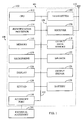
- the present invention is embodied in a system 100 illustrated in the functional block diagram of FIG. 1 .
- the system 100 includes a wireless communication device 101 and an external accessory 201, two of which are illustrated in FIG. 2 as either a headset accessory 202 or a carkit accessory 210.
- an external accessory 201 two of which are illustrated in FIG. 2 as either a headset accessory 202 or a carkit accessory 210.
- the wireless communication device 101 which may be embodied in a cellular telephone, includes a housing 102 that contains a transmitter 104 and a receiver 106 to allow transmission and reception of data, such as audio communications, between the system 100 and a remote location, such as a cell site controller (not shown).
- the transmitter 104 and receiver 106 may be combined into a transceiver 108.
- An antenna 110 is attached to the housing 102 and electrically coupled to the transceiver 108.
- the operation of the transmitter 104, receiver 106, and antenna 110 is well known in the art and need not be described herein.
- the wireless communication device 101 also includes a central processing unit (CPU) 112, which controls operation of the system 100.
- the CPU 112 may perform all the tasks involved with the operation of the system 100, or only a portion of them, where the remaining tasks are delegated to other processing units included in the system.
- the wireless communication device 101 may include, in addition to CPU 112, an identification processor 114 for receiving and processing identification data.
- the identification data reflects whether the wireless communication device 101 is connected to an external accessory, and identifies the specific external accessory if one is connected.
- the identification processor 114 and the identification data will be described in greater detail below.
- the wireless communication device 101 further includes a memory 116 which may include both read-only memory (ROM) and random access memory (RAM). A portion of the memory 116 may also include non-volatile random access memory to store information that must be present upon powering up the wireless communication device 101.
- the memory 116 is used generally to store instructions and data for processing by the CPU 112.
- the wireless communication device 101 also includes an output data memory 118 that is devoted to storing information such as user programmable volume levels and the associated menu titles or labels for earpiece, ringer, key beep, and message alerts of the wireless communication device 101.
- the output data memory 118 may also store the identification data of an external accessory 201 connected to the wireless communication device 101.
- the wireless communication device 101 also includes an audio input device, such as a microphone 120, and an audio output device, such as a speaker 122.
- the microphone 120 and speaker 122 operate in a conventional manner to provide two-way audio communication using the wireless communication device 101.
- the speaker 122 is driven by driving signals generated by an output driver 124.
- the driving signals provided by the output driver 124 will be converted by the speaker 122 into audible signals to transmit the voice of the caller to the user, or produce audible cues that assist the user in operating the wireless communication device 101.
- the wireless communication device 101 also includes a display 126 to conveniently display user instructions as well as user-entered data, such as destination telephone numbers and alphanumeric text.
- the information shown on the display 126 provides visual cues that assist the user in the operation of the system 100.
- a keypad 128 is attached to the housing 102 for operation by the user in a conventional manner. The keypad 128 provides a convenient input device by which destination telephone numbers and commands may be entered by the user.
- the electrical components of the system 100 receive power from a battery 130, which is attached to and supported by the housing 102.
- the battery 130 is a rechargeable battery.
- the system 100 may include a connector (not shown) for the connection of an external power source, such as an automobile power adapter, AC power adapter, or the like.
- bus system 132 of the wireless communication device 101 which may include a power bus, control signal bus, and status signal bus in addition to a data bus.
- bus system 132 may include a power bus, control signal bus, and status signal bus in addition to a data bus.
- the various buses are illustrated in FIG. 1 as the bus system 132.
- External accessories 201 may be connected to wireless communication device 101 through an accessory port 136.
- the external accessories are connected to the bus system 132 through the accessory port 136.
- the external accessory 201 allows the wireless communication device to be used in a wide range of applications.
- the external accessory 201 has an extension cord 208.
- a connector 209 at the end of the extension cord 208 allows the external accessory 201 to be coupled to the accessory port 136 of the wireless communication device 101.
- the external accessory 201 is manufactured by the same manufacturer of the wireless communication device 101, thereby insuring compatibility between the two.
- the external accessories 201 are the headset accessory 202 and the carkit accessory 210, which are illustrated in FIG. 2 .
- the headset accessory 202 is useful because the user does not need to hold the wireless communication device 101 during operation.
- the mouthpiece 204 and earpiece 206 are positioned by the headset 201 accessory and are used in place of the microphone 120 and speaker 122 (see FIG. 1 ) of the wireless communication device 101 whenever the headset accessory 202 is connected.
- the carkit accessory 210 is also useful because an external microphone 212 attached to the interior of an automobile is used in place of the microphone 120, and the audible output signals produced by the wireless communication device are transmitted over an audio system 214 in the automobile. Thus, the user can use the wireless communication device and continue to drive using both hands without any distractions from trying to hold the wireless communication device.
- the carkit accessory 210 shown in FIG. 2 is a non-coil-cord carkit, where the cord 208 connecting the external accessory 210 to the wireless communication device 101 is a straight cord.
- Other types of carkits are available where the cord 208 is a coil, such as those commonly used on conventional telephones.
- a battery charger that charges the rechargeable battery 130 in the wireless communication device 101 is another common external accessory.
- a computer interface for a personal computer or laptop is yet another possible external accessory that can be coupled to the wireless communication device 101 via the accessory port 136. Illustrations of these other external accessories 201 are not shown or described in detail herein because they are familiar to those skilled in the art.
- the wireless communication device 101 In order to support the operation of external accessory 201 and to update the user interface properly upon connection, the wireless communication device 101 needs to be able to identify external accessory 201 when it is first connected.
- the identification processor 114 does this by monitoring existing lines in the accessory port 136. Extensions of these lines run through the cord 208.
- the accessory port 136 is a pulse code modulation (PCM) port that transfers data between the wireless communication device 101 and the external accessory 201.
- the PCM port has four lines or pins.
- One of the lines is a PCM-Data-In (PCM-DIN) line for the transmission of data from the external accessory 201 to the wireless communication device 101.
- the identification processor 114 monitors this line for a voltage or status signal that indicates when an external accessory 201 is connected to the wireless communication device 101 and then for a device identification (ID) code of the external accessory 201.
- ID device identification
- the other three lines in the accessory port 136 are a PCM-Data-Out (PCM-DOUT) line for transmission of data from the wireless communication device 101 to the external accessory 201, a clock line, and a synchronization line.
- PCM-DOUT PCM-Data-Out
- the PCM port can also have a fifth line for grounding. It is to be appreciated that in some embodiments, the PCM port can have more or fewer lines. For example, clock and synchronization signals could be transmitted over the same line. Power and signal ground can share the same line.
- the external accessory 201 has an external power supply that supplies power to the wireless communication device 101, then a voltage level is detected by the identification processor 114 on a General Purpose Input/Output (GPIO) line of the wireless communication device 101.
- the GPIO line can be a part of the PCM port, or it can be a line external to the PCM port lines described above. PCM is not described herein in detail because it is familiar to those skilled in the art.
- the PCM-DIN line remains at low logic level when there is no external accessory 201 attached to the accessory port 136.
- Low logic level can be defined as either zero voltage level, a low voltage level, or a negative voltage level.
- Most external accessories, except for battery chargers, will transmit high logic level on the PCM-DIN line when the external accessory 201 is attached to the accessory port 136.
- High logic level is defined to be a voltage level higher than the low logic level voltage.
- FIG. 3 is a table listing several external accessories 201 and whether a particular external accessory 201 inserts a high logic level on the PCM-DIN line upon connection. The information shown in the table of FIG. 3 for known external accessories is stored in the memory 116 or in the output data memory 118, so that when a particular external accessory 201 is connected, the logic levels transmitted by the external accessory 201 are compared by the identification processor 114 with this known information.
- the external accessory 201 Upon connection, the external accessory 201 transmits high logic level which may be in the form of pulses on the PCM-DIN line.
- the pulse width of low logic level is preferably set to be shorter than 50 milliseconds.
- the identification processor 114 is clocked to constantly monitor the PCM-DIN line in 50 millisecond intervals. If any high logic level is detected within this time interval, it indicates that an external accessory 201 has just attached to the wireless communication device 101. Otherwise, there is no external accessory 201 connected.
- a battery charger may be connected to the accessory port 136. Because the charger does not transfer data to the wireless communication device 101, the logic level on the PCM-DIN line remains low, as indicated in the table of FIG. 3 .
- a person skilled in the art would know how to program the identification processor 114 to monitor the PCM-DIN line during intervals determined by a clock.
- Some external accessories 201 such as the carkit 210 and a battery charger, also supply external power to the wireless communication device 101.
- the table of FIG. 3 identifies the external accessories 201 that supply external power.
- the identification processor 114 detects the presence of a voltage level coming from an external power line through a detector connected to a GPIO line of the wireless communication device 101. This voltage level, whether logic high or logic low, provides additional indication as to whether an external accessory 201 has been connected. For example, as shown in the table of FIG. 3 , if the identification processor 114 detects both a low logic level on the PCM-DIN line and presence of external power, then it determines that a battery charger is connected. If the identification processor 114 detects the other combinations shown in the table of FIG.
- the identification processor 114 checks for a third set of information -- the device ID code of the external accessory 201 -- on the PCM-DIN line, as will be described below.
- the external power information for known external accessories is also stored in the memory 116 or in the output data memory 118, so that the identification processor 114 can compare the transmitted information with the known information stored in the memory 116 or in the output data memory 118.
- Data transmitted by the external accessory 201 to the wireless communication device 101 along the data lines of the PCM port, including the device ID, are in a serial stream.
- the PCM data runs at a data rate of 128K bits/second. Eight bits out of every 16 bits are used to carry Vocoder data, which are compressed samples of audio data or fax data, for example. The remaining 8 bits of the 16 bits are known as the "pad-byte" or "pad character.”
- the pad-byte is used to carry the ID information of the external accessory 201 during the communication interface between the external accessory and the wireless communication device 101.
- the external accessory 201 places a unique value in this pad-byte upon connection to wireless communication device 101.
- the unique value of the ID information is shown by the representative values listed in the table of FIG. 3 .
- the device ID of the headset 202 is C1 hexadecimal.
- These known values are also stored in the memory 116 or in the output data memory 118, so that the identification processor 114 can compare the ID information actually received from the external accessory 201 with the known values to identify the external accessory.
- the identification processor 114 reads the pad-byte multiple times, with minimum delay after each reading, to make sure that the data is consistent.
- the identification processor 114 synchronizes the transmission and reading of the data by generating a clock signal.
- the delay between reading periods, as defined by the clock signal is 125 microseconds, which is the transmission time of each pad-byte.
- the external accessory 201 transmits the pad-byte data in response to receiving the clock signal.
- the identification processor 114 processes the signals and device ID data based on logic states of the system 100. That is, the identification processor 114 performs a particular function and remains in a predetermined state until directed to perform a different function and thereby change states.
- Software instructions referred to as "keys,” represent a change of states. For instance, a key may indicate that the identification processor 114 is toggling from monitoring for the high logic level status signal on the PCM-DIN line to reading the transmitted ID code.
- the table shown in FIG. 4 lists several representative keys and the corresponding status that the keys represent.
- FIG. 5 illustrates a state machine flow chart 500 describing the operation of the system 100 using the keys listed in the table of FIG. 4 and the information shown in the table of FIG. 3 .
- the encircled quantities represent different states of the system 100.
- the directional arrows, showing the delivery of various keys, represent a change from one state to another. Operation of this state machine flow chart 500 will be explained below for the headset 202 and the non-coil-cord carkit 210.
- the process to identify these two external accessories can be extended to identify the other external accessories listed in the table of FIG. 3 .
- the HS_EXT_POWER_ON_K key 510 indicates that external power from an external accessory 201 has been detected by the identification processor 114 on the GPIO line.
- key 510 would then direct the identification processor 114 to change to the next state of monitoring for a high logic level on the PCM-DIN line.
- the keys listed in the table of FIG. 4 drive system 100 from one state to another and towards the state in which the external accessory 201 is fully identified.
- the wireless communication device 101 is powered by the battery 130 if there is no external accessory 201 connected to the accessory port 136. It is noted that a state 132, indicated as LPM (Low Power Mode), could also have been chosen as an initial state, when there is minimum power being supplied to the wireless communication device 101.
- LPM Low Power Mode
- the identification processor 114 monitors for both a high logic level on the PCM-DIN line and a voltage on the GPIO line that indicates an external power source.
- a HS_EXT_PWR_ON_K key 510 is delivered to change the state of the system 100 from state 130 to state 550.
- the combination of an external power source and low logic level on the PCM-DIN line indicates that a charger is coupled to the wireless communication device 101.
- the identification processor 114 determines whether a headset 202, a computer interface, or an unknown device coupled to the wireless communication device 101. If the identification processor 114 does detect a high logic level on the PCM-DIN line, which indicates the connection of some type of external accessory 201, then a HS_EXT_DEV_K key 504 is delivered to change the state of the system 100 from state 130 to state 552. In state 552, the identification processor 114 then checks for external power on the GPIO line. System 100 remains in state 552 if no external power is detected on the GPIO line, and checks for a device ID in the pad-byte of the data transmitted on the PCM-DIN line. From a review of the table of FIG. 3 , this combination of high logic level on the PCM-DIN line and no external power on the GPIO line indicates that there is a headset 202, a computer interface, or an unknown device coupled to the wireless communication device 101.
- a pad-byte corresponding to hexadecimal ID C1 shown in the table of FIG. 3 for a headset 202, is detected by identification processor 114, a HS_HEADSET_K key 508 is delivered to change the state of the system 100 from state 552 to state 202. Once this final identification is made, the wireless communication device 101 can properly interface with the headset 202.
- identification processor 114 reads the pad-byte data repeatedly, as determined by the clock signal, to verify that there is no error in the pad-byte.
- identification processor 114 If, back in state 552, the identification processor 114 had detected external power on the GPIO line, then an HS_EXT_PWR_ON_K key 514 would have been delivered. This key 514 would change the state of the system 100 from state 552 to state 554. As will be described later below, at state 554, identification processor 114 reads the device ID transmitted from the coupled external accessory 201.
- a HS_PHONE_K key 506 is delivered to change the state of the system 100 from state 202 to state 130.
- Key 506 changes the PCM-DIN line back to logic low so that identification processor 114 can monitor for the next connection.
- Key 506 is delivered whenever an external accessory 201 is disabled or disconnected from the wireless communication device 101.
- this condition indicates that a battery charger, a computer interface, a non-coil-cord carkit 210, a coil-cord carkit, or an unknown device, is supplying external power to the wireless communication device 101.
- the HS_EXT_PWR_ON_K key 510 shown at the top of FIG. 5 , is delivered to change the state of the system 100 from state 130 to state 550. The delivery of key 510 also simultaneously disables the battery 130.
- the identification processor 114 then checks to see if the PCM-DIN line has high logic level. If high logic level is not detected on the PCM-DIN line, the system 100 remains in state 550, signifying that a charger is connected to the accessory port 136 (see FIG. 3 ).
- a HS_EXT_DEV_K key 505 is delivered to change the state of the system 100 from state 550 to state 554.
- the combination of external power on the GPIO line and logic high level status on the PCM-DIN line indicates a connection of a carkit, a computer interface, or an unknown device.
- the identification processor 114 repeatedly reads for a device ID in the pad-byte of the transmitted data from the connected external accessory 201, using the clock intervals discussed above.
- the identification processor 114 first checked for external power on the GPIO line, and then subsequently checked for a high logic level status on the PCM-DIN line. In this fashion, the state of system 100 changed sequentially from state 130, to state 550, and to state 554. It is also possible to program the identification processor 114 to first check for the high logic level status on the PCM-DIN line before it checks for external power on the GPIO line. If identification processor 114 does this, the system 100 would change from state 130, to state 552, and to state 554. The end result is the same-the system 100 is at state 554.
- a HS_HFK_NOCORD_K key 512 is delivered to complete the interface by changing the state of the system 100 from state 554 to state 210.
- state 210 is indicated as "HFK.”
- HFK signifies a "Hands-Free Kit” for a carkit. It is to be appreciated that it would have been possible in state 554 to detect the device ID of other external accessories 201 that have an external power source and that transmit a high logic status on the PCM-DIN line. The corresponding keys for these external accessories 201, as shown in FIG. 4 , would have been delivered in place of HS_HFK_NOCORD_K key 512.
- a HS_PHONE_K key 509 and a HS_EXT_PWR_OFF_K key 502 are delivered, resulting in the system 100 sequentially changing states from state 210, to state 550, and finally to state 130, where the phone battery 130 (see Fig. 1 ) resumes supplying power to the wireless communication device 101.
- the identification processor 114 returns to the state where it monitors for high logic level status on the PCM-DIN line and for external power on the GPIO line.
- FIG. 5 shows how the identification processor 114 processes these events. For example, if a headset 202 is connected while the identification processor 114 is still in the process of reading the device ID of the headset 202 in state 552, the user may suddenly disconnect the headset 202 and connect the carkit 210 to the accessory port 136. The momentary disconnection of the headset 202 will result in a HS_PHONE_K key 507 being delivered to change the state of the system 100 from state 552 to state 130.
- the identification processor 114 will detect external power on the GPIO line and start a new identification procedure for the carkit 210, including the initial step of delivering the HS_EXT_PWR_ON_K key 510 to change the state of the system 100 from state 130 to state 550.
- the process of identifying the carkit 210 then repeats as previously described above.
- the flow chart 500 of FIG.5 illustrates how this and other identification processes can be accomplished, and a person skilled in art would understand how these processes are accomplished by reviewing the figure.
- the identification processor 114 provides appropriate instructions to the other elements shown in FIG. 1 in housing 102 so that the user can perform functions such as adjusting the volume levels of the wireless communication device 101 or any of the accessories 201 which may be coupled to the wireless communication device. For example, once the type of external accessory 201 has been identified, the identification processor 114 generates selection data to select the appropriate program volumes for the external accessory 201 or the wireless communication device 101, which are stored in output data memory 118. The information in the output data memory 118 determines the output level at which output driver 124 will generate driving signals to drive the corresponding output device. The display 126 shows the volume level and a label for the external accessory 201 corresponding to that volume level.
Claims (17)
- Ein Drahtloskommunikationsgerät (101) koppelbar an ein externes Zusatzgerät (201), wobei die Vorrichtung Folgendes aufweist:- einen Transceiver (108) zum Senden und Empfangen von Daten und Audiokommunikationen zwischen der Drahtloskommunikationsvorrichtung (101) und einem entfernten Ort;- ein Zusatzgeräte-Port (136) zum Empfangen einer Datenleitung angebunden an das externe Zusatzgerät, um es dem externen Zusatzgerät (201) zu ermöglichen an die Drahtloskommunikationsvorrichtung (101) gekoppelt zu werden;- ein Prozessor (114) konfiguriert zum Abfühlen einer Aktivität auf der Datenleitung und zum Erlangen eines logischen Pegels auf der Datenleitung, wenn das externe Zusatzgerät (201) gekoppelt wird an die Drahtloskommunikationsvorrichtung, wobei der Prozessor (114) weiterhin konfiguriert ist zum Überwachen einer allgemeinen Eingabe-/Ausgabeleitung, um Informationen darüber zu erhalten, ob das externe Zusatzgerät ihre eigene Stromquelle besitzt und für die Verwendung des logischen Pegels und der Information zum Bestimmen, ob Identifikationsdaten gelesen werden sollen und dann zum Abfühlen von Identifikationsdaten, die dem externen Zusatzgerät zugeordnet sind auf der Datenleitung und zum Verwenden der Identifikationsdaten zum Identifizieren des externen Zusatzgeräts;- ein Ausgabetreiber (124) zum Generieren von Ausgabesignalen, wobei die Ausgabesignale gekoppelt sind an das externe Zusatzgerät (201) über dem Zusatzgeräte-Port, wenn das externe Zusatzgerät an die Drahtloskommunikationsvorrichtung gekoppelt ist; und- ein Speicherort (116) gekoppelt an den Prozessor (114), wobei der Speicherort Daten, die einer Vielzahl von externen Zusatzgeräten zugeordnet sind speichert, wobei die gespeicherten Daten einen Identifikationscode entsprechend einem beliebigen der Vielzahl von externen Zusatzgeräten beinhaltet und der Prozessor (114) die gesendeten Identifikationsdaten mit den gespeicherten Daten vergleicht, um das externe Zusatzgerät zu identifizieren, wenn das externe Zusatzgerät an die Drahtloskommunikationsvorrichtung (101) gekoppelt ist.
- Vorrichtung nach Anspruch 1, wobei die Aktivität ein Signal umfasst, das von dem externen Zusatzgerät (201) gesendet wird, wenn das externe Zusatzgerät an die Drahtloskommunikationsvorrichtung gekoppelt wird und die Kommunikationsdaten einen Identifikationscode für das externe Zusatzgerät beinhalten.
- Vorrichtung nach Anspruch 1, wobei die Datenleitung ein Teil eines Pulscodemodulations- bzw. PCM-Ports ist, und der PCM-Port an den Zusatzgerät-Port (136) koppelbar ist.
- Vorrichtung nach Anspruch 1, wobei die Eingabe/Ausgabeleitung zum Senden einer Spannung dient, zum Anzeigen dafür, ob das externe Zusatzgerät eine externe Leistung an die Drahtloskommunikationsvorrichtung (101) liefert, wenn das externe Zusatzgerät an die Drahtloskommunikationsvorrichtung gekoppelt wird.
- Vorrichtung nach Anspruch 1, wobei der Prozessor (114) ein Taktsignal generiert, wobei der Prozessor die Identifikationsdaten gesendet von dem externen Zusatzgerät (201) während einer Zeitperiode definiert durch das Taktsignal liest.
- Vorrichtung nach Anspruch 1, wobei der Identifikationscode eine binäre Zahl ist.
- Vorrichtung nach Anspruch 1, wobei das externe Zusatzgerät eines der Folgenden ist, eine Autofreisprechanlage (210) zur Verwendung in einem Fahrzeug mit einem Audiosystem (214), eine Freisprechvorrichtung (202), eine Computerschnittstelle, wobei das externe Zusatzgerät (201) die Identifikationsdaten auf der Datenleitung sendet, wenn das externe Zusatzgerät an die Drahtloskommunikationsvorrichtung (101) gekoppelt wird.
- Vorrichtung nach Anspruch 1, wobei das externe Zusatzgerät (201) ein Ladegerät ist zum Vorsehen von Leistung bzw. Energie an die Drahtloskommunikationsvorrichtung, wenn das Ladegerät an die Drahtloskommunikationsvorrichtung gekoppelt wird.
- Vorrichtung nach Anspruch 1, die weiterhin Folgendes aufweist:- ein Gehäuse (102);- wobei der Zusatzgeräte-Port an dem Gehäuse montiert ist und für das externe Zusatzgerät erreichbar ist, um es dem externen Zusatzgerät zu ermöglichen an die Drahtloskommunikationsvorrichtung gekoppelt zu werden, wobei der Zusatzgeräte-Port zumindest eine der Datenleitung aufweist.
- Vorrichtung nach Anspruch 9, wobei der Prozessor ein Taktsignal generiert, das an den Zusatzgeräte-Port gekoppelt wird, wobei das externe Zusatzgerät die Identifikationsdaten an die Drahtloskommunikationsvorrichtung über die Datenleitung schickt, und zwar ansprechend auf das Taktsignal, wenn das externe Zusatzgerät an die Drahtloskommunikationsvorrichtung gekoppelt wird.
- Vorrichtung nach Anspruch 10, die weiterhin eine Taktleitung aufweist, die an den Zusatzgeräte-Port und an das externe Zusatzgerät gekoppelt ist, wobei die Drahtloskommunikationsvorrichtung das Taktsignal an das externe Zusatzgerät über die Taktleitung sendet.
- Ein Verfahren zum Bestimmen, wann ein externes Zusatzgerät an einen Zusatzgeräte-Port einer Drahtloskommunikationsvorrichtung gekoppelt ist und zum Identifizieren des externen Zusatzgeräts, wobei das Verfahren folgende Schritte aufweist:- Überwachen einer Datenleitung nach einer Aktivität, zum Anzeigen dafür wann das externe Zusatzgerät an die Drahtloskommunikationsvorrichtung gekoppelt wird, um einen logischen Pegel der Datenleitung zu erhalten;- Überwachen einer allgemeinen bzw. Allzweck-Eingabe/Ausgabeleitung, um Informationen darüber zu erhalten, ob das externe Zusatzgerät ihre eigene Energiequelle besitzt;- Verwenden des logischen Pegels und der Information um zu Bestimmen, ob die Identifikationsdaten gelesen werden sollen und dann:Lesen von Identifikationsdaten gesendet durch das externe Zusatzgerät auf der Datenleitung, wenn das externe Zusatzgerät an die Drahtloskommunikationsvorrichtung gekoppelt wird; undVergleichen der gesendeten Identifikationsdaten mit gespeicherter Information, die einer Vielzahl von externen Zusatzgeräten zugeordnet ist, um das externe Zusatzgerät zu identifizieren.
- Verfahren nach Anspruch 12, wobei der Schritt des Überwachens der Eingabe/Ausgabeleitung das Überprüfen hinsichtlich einer Spannung beinhaltet, anzeigend dafür, ob das externe Zusatzgerät externe Leistung an die Drahtloskommunikationsvorrichtung liefert.
- Verfahren nach Anspruch 12, die weiterhin den Schritt des Generierens eines Taktsignals aufweist, wobei die Überwachungs- und Leseschritte ansprechend auf eine Zeitperiode definiert durch das Taktsignal auftreten.
- Verfahren nach Anspruch 14, wobei der Schritt des Sendens des Taktsignals zu dem externen Zusatzgerät aufweist, wobei das externe Zusatzgerät die Identifikationsdaten ansprechend auf das Taktsignal sendet.
- Verfahren nach Anspruch 12, das weiterhin Folgendes aufweist: Wiederholen der Lese- und Vergleichsschritte, um eine konsistente Identifikation der Identifikationsdaten zu erlangen.
- Verfahren nach Anspruch 12, das weiterhin das Wiederholen des Überwachungsschrittes aufweist, um zur Detektieren, wann das externe Zusatzgerät angekoppelt oder abgekoppelt wird von der Drahtloskommunikationsvorrichtung.
Applications Claiming Priority (3)
| Application Number | Priority Date | Filing Date | Title |
|---|---|---|---|
| US229131 | 1999-01-12 | ||
| US09/229,131 US6725061B1 (en) | 1999-01-12 | 1999-01-12 | System and method for the automatic identification of accessories coupled to a wireless communication device |
| PCT/US2000/000662 WO2000042797A1 (en) | 1999-01-12 | 2000-01-11 | System and method for the automatic identification of accessories coupled to a wireless communication device |
Publications (2)
| Publication Number | Publication Date |
|---|---|
| EP1145578A1 EP1145578A1 (de) | 2001-10-17 |
| EP1145578B1 true EP1145578B1 (de) | 2010-03-03 |
Family
ID=22859947
Family Applications (1)
| Application Number | Title | Priority Date | Filing Date |
|---|---|---|---|
| EP00903242A Expired - Lifetime EP1145578B1 (de) | 1999-01-12 | 2000-01-11 | System und verfahren zur automatischen identifizierung von zubehören , welche gekuppelt sind mit einem schnurlosen kommunikationsgerät |
Country Status (12)
| Country | Link |
|---|---|
| US (1) | US6725061B1 (de) |
| EP (1) | EP1145578B1 (de) |
| JP (1) | JP4624565B2 (de) |
| KR (2) | KR20080053415A (de) |
| CN (1) | CN1160983C (de) |
| AU (1) | AU2501800A (de) |
| CA (1) | CA2360799A1 (de) |
| DE (1) | DE60043927D1 (de) |
| HK (1) | HK1044261B (de) |
| IL (2) | IL144258A0 (de) |
| MX (1) | MXPA01007058A (de) |
| WO (1) | WO2000042797A1 (de) |
Families Citing this family (108)
| Publication number | Priority date | Publication date | Assignee | Title |
|---|---|---|---|---|
| EP1641309B8 (de) * | 1999-06-14 | 2011-02-02 | Ntt Docomo, Inc. | Batterieeinheit und Ladegerät für ein drahtloses Telekommunikationsgerät |
| WO2001019060A1 (en) * | 1999-09-03 | 2001-03-15 | Nokia Mobile Phones Limited | Mobile communications device with speaker dependent audio adjustment |
| US20050259015A1 (en) * | 2000-03-31 | 2005-11-24 | Fujitsu Limited | Electronic equipment |
| US6917817B1 (en) * | 2000-07-28 | 2005-07-12 | Delphi Technologies, Inc. | Modem integrated into a radio receiver utilizing a communication port |
| JP2002101156A (ja) | 2000-09-22 | 2002-04-05 | Sony Corp | 携帯電話機及び音声処理方法 |
| US7593723B2 (en) * | 2001-05-10 | 2009-09-22 | Rony Zarom | Modular personal device system |
| JP3671880B2 (ja) | 2001-07-18 | 2005-07-13 | ソニー株式会社 | 通信システムおよび方法、情報処理装置および方法、通信端末および方法、拡張装置、並びにプログラム |
| JP3671881B2 (ja) * | 2001-07-18 | 2005-07-13 | ソニー株式会社 | 通信システムおよび方法、情報処理装置および方法、通信端末および方法、拡張装置、並びにプログラム |
| EP1442619A2 (de) * | 2001-08-14 | 2004-08-04 | Koninklijke Philips Electronics N.V. | Verfahren und system zur bereitstellung von programmierungs-informationen zur programmierung eines gerätes |
| US20030127176A1 (en) * | 2001-09-12 | 2003-07-10 | Shin-Etsu Chemical Co., Ltd. | Optical device, optical isolator and method for producing the same |
| KR20010110378A (ko) * | 2001-11-07 | 2001-12-13 | 최성원 | 복수 단말기 교체와 인식이 가능한 이동통신 모듈 |
| DE60109049T2 (de) * | 2001-12-07 | 2006-04-06 | Sony International (Europe) Gmbh | Von einem vorherigen Kodewert abhängige Erkennung von von einem Zubehörgerät zu einem mobilen Endgerät gesendeten Übertragungskoden |
| EP1318576A1 (de) * | 2001-12-07 | 2003-06-11 | Sony International (Europe) GmbH | Jack-Steckverbinder für Jack-Stecker mit unterschiedlicher Kontaktenzahl |
| FI111891B (fi) * | 2001-12-20 | 2003-09-30 | Nokia Corp | Päätelaitteen tunnistaminen |
| JPWO2003060732A1 (ja) * | 2002-01-16 | 2005-05-19 | 富士通株式会社 | 携帯端末並びに該携帯端末用の外部機器,外部機器認識方法及び外部機器認識プログラム |
| US7024230B2 (en) * | 2002-02-22 | 2006-04-04 | Kyocera-Wireless Corp | Accessory interface system |
| US7050783B2 (en) * | 2002-02-22 | 2006-05-23 | Kyocera Wireless Corp. | Accessory detection system |
| WO2004006547A1 (en) * | 2002-07-04 | 2004-01-15 | Sennheiser Communications A/S | Wireless communication systems. |
| US7062261B2 (en) * | 2003-01-31 | 2006-06-13 | Motorola, Inc. | Method and apparatus for automatic detection and installation of Java-enabled accessories |
| EP1639794A1 (de) * | 2003-06-18 | 2006-03-29 | Philips Intellectual Property & Standards GmbH | Diebstahlschutzsystem für tragbare elektronische geräte. |
| US7130665B2 (en) * | 2003-08-26 | 2006-10-31 | Motorola, Inc. | Method and apparatus to ensure intrinsically safe operation of a communication device |
| US20050064822A1 (en) * | 2003-09-23 | 2005-03-24 | Higgins Robert J. | Audio accessory optimization system |
| US7424312B2 (en) * | 2003-09-23 | 2008-09-09 | Motorola, Inc. | Interface system for an accessory and a communication device |
| ATE392771T1 (de) * | 2003-12-12 | 2008-05-15 | Sony Ericsson Mobile Comm Ab | Zubehörsidentifizierungsalgorithmus für systemstecker |
| KR100576026B1 (ko) * | 2004-01-08 | 2006-05-02 | 삼성전자주식회사 | 종합 단말에서 호스트부와 클라이언트부의 양방향 검출장치 |
| US6995857B2 (en) * | 2004-01-23 | 2006-02-07 | Vpr Matrix, Inc. | System and method for routing service requests from a paired digital camera and transceiver module |
| US7826318B2 (en) * | 2004-04-27 | 2010-11-02 | Apple Inc. | Method and system for allowing a media player to transfer digital audio to an accessory |
| US7441062B2 (en) * | 2004-04-27 | 2008-10-21 | Apple Inc. | Connector interface system for enabling data communication with a multi-communication device |
| US7441058B1 (en) | 2006-09-11 | 2008-10-21 | Apple Inc. | Method and system for controlling an accessory having a tuner |
| US7529871B1 (en) | 2004-04-27 | 2009-05-05 | Apple Inc. | Communication between an accessory and a media player with multiple protocol versions |
| US8117651B2 (en) | 2004-04-27 | 2012-02-14 | Apple Inc. | Method and system for authenticating an accessory |
| US7895378B2 (en) | 2004-04-27 | 2011-02-22 | Apple Inc. | Method and system for allowing a media player to transfer digital audio to an accessory |
| US7673083B2 (en) * | 2004-04-27 | 2010-03-02 | Apple Inc. | Method and system for controlling video selection and playback in a portable media player |
| US7529870B1 (en) * | 2004-04-27 | 2009-05-05 | Apple Inc. | Communication between an accessory and a media player with multiple lingoes |
| US7797471B2 (en) | 2004-04-27 | 2010-09-14 | Apple Inc. | Method and system for transferring album artwork between a media player and an accessory |
| US7526588B1 (en) | 2004-04-27 | 2009-04-28 | Apple Inc. | Communication between an accessory and a media player using a protocol with multiple lingoes |
| US7529872B1 (en) | 2004-04-27 | 2009-05-05 | Apple Inc. | Communication between an accessory and a media player using a protocol with multiple lingoes |
| KR100619898B1 (ko) * | 2004-08-24 | 2006-09-19 | 엘지전자 주식회사 | 외부장치 감지 기능을 갖는 이동통신 단말기 및 그 방법 |
| CN1797978B (zh) * | 2004-12-29 | 2010-05-05 | 集嘉通讯股份有限公司 | 一种无线通信装置的名称显示方法与系统 |
| US7525216B2 (en) * | 2005-01-07 | 2009-04-28 | Apple Inc. | Portable power source to provide power to an electronic device via an interface |
| US7823214B2 (en) | 2005-01-07 | 2010-10-26 | Apple Inc. | Accessory authentication for electronic devices |
| US20060158154A1 (en) * | 2005-01-18 | 2006-07-20 | Maurilus Jean R | Method and apparatus for backing up data from cell phones and other hand-held devices |
| GB2424342A (en) * | 2005-02-23 | 2006-09-20 | Nec Technologies | Mobile Handset Security System |
| JP4239988B2 (ja) | 2005-03-07 | 2009-03-18 | ソニー株式会社 | 通信システム、通信装置、有線通信装置、および通信方法 |
| US20060223580A1 (en) * | 2005-03-31 | 2006-10-05 | Antonio Franklin P | Mobile device interface for input devices using existing mobile device connectors |
| EP1717910B1 (de) * | 2005-04-27 | 2011-12-14 | LG Electronics Inc. | Mobiles Kommunikationsendgerät mit Multifunktionsanschlussdose und entsprechendes Verfahren |
| US20070005605A1 (en) * | 2005-06-30 | 2007-01-04 | Hampton Arthur D | System and method for selectively delivering content to a user having one or more accessible devices |
| US7398105B2 (en) * | 2005-09-06 | 2008-07-08 | Sarandis Kalogeropoulos | Mobile communication device and accessory therefor |
| KR100728637B1 (ko) * | 2005-09-08 | 2007-06-15 | (주)한창시스템 | 플러그-인 형태로 여러 가지 보안 모듈들을 지원하는 보안nfc 통신 장치 및 방법 |
| US7346368B2 (en) * | 2005-10-04 | 2008-03-18 | Research In Motion Limited | Method and mobile device for operating in different data transfer modes |
| EP1773038B1 (de) * | 2005-10-04 | 2008-04-30 | Research In Motion Limited | Verfahren und mobile Einrichtung zum Bedienen in unterschiedlichen Datenübertragungsmodi |
| US7303007B2 (en) * | 2005-10-07 | 2007-12-04 | Weatherford Canada Partnership | Method and apparatus for transmitting sensor response data and power through a mud motor |
| US8086332B2 (en) * | 2006-02-27 | 2011-12-27 | Apple Inc. | Media delivery system with improved interaction |
| DE102006021464A1 (de) * | 2006-05-09 | 2007-11-15 | Bayerische Motoren Werke Ag | Verfahren zur Prüfung der Kompatibilität eines Steuergerätes einer Kraftfahrzeugfreisprecheinrichtung mit einem Mobiltelefon und Fahrzeug |
| US8006019B2 (en) | 2006-05-22 | 2011-08-23 | Apple, Inc. | Method and system for transferring stored data between a media player and an accessory |
| US8073984B2 (en) | 2006-05-22 | 2011-12-06 | Apple Inc. | Communication protocol for use with portable electronic devices |
| US7415563B1 (en) * | 2006-06-27 | 2008-08-19 | Apple Inc. | Method and system for allowing a media player to determine if it supports the capabilities of an accessory |
| KR100754825B1 (ko) * | 2006-06-30 | 2007-09-04 | 삼성전자주식회사 | 휴대 단말기에서 모바일 커머스 제공 장치 및 방법 |
| US7513090B2 (en) * | 2006-07-11 | 2009-04-07 | Automated Packaging Systems, Inc. | Apparatus and method for making fluid filled units |
| US7558894B1 (en) | 2006-09-11 | 2009-07-07 | Apple Inc. | Method and system for controlling power provided to an accessory |
| WO2008041064A2 (en) * | 2006-10-06 | 2008-04-10 | Freescale Semiconductor, Inc. | Detection circuit for detecting the connection of an accessory to a mobile device and method thereof |
| JP2008158785A (ja) * | 2006-12-22 | 2008-07-10 | Toshiba Corp | デバイスの接続方法、情報処理装置、及びデバイス接続用プログラム |
| US20080182442A1 (en) * | 2007-01-31 | 2008-07-31 | Jaeho Choi | Data Port for a Mobile Device |
| KR100819242B1 (ko) * | 2007-04-23 | 2008-04-03 | 삼성전자주식회사 | 휴대 단말기에서의 외부 장치를 인식하기 위한 시스템 및방법 |
| US8086781B2 (en) * | 2007-06-22 | 2011-12-27 | Apple Inc. | Serial pass-through device |
| US8078787B2 (en) | 2007-06-22 | 2011-12-13 | Apple Inc. | Communication between a host device and an accessory via an intermediate device |
| AU2008296673B2 (en) * | 2007-09-04 | 2010-05-27 | Apple Inc. | Smart dock for chaining accessories |
| WO2009032708A2 (en) * | 2007-09-04 | 2009-03-12 | Apple Inc. | Protocol for remote user interface for portable media device |
| US20090091422A1 (en) * | 2007-10-03 | 2009-04-09 | Apple Inc. | Device identification via serial communication link |
| KR101339822B1 (ko) * | 2007-10-15 | 2013-12-11 | 삼성전자주식회사 | 외부 장치에 따른 단말기 제어 방법 및 이를 이용하는 휴대단말기 |
| CN101426038B (zh) * | 2007-10-29 | 2011-06-08 | 深圳富泰宏精密工业有限公司 | 便携式电子装置及其附件鉴别方法 |
| US8520860B2 (en) * | 2007-12-13 | 2013-08-27 | Symbol Technologies, Inc. | Modular mobile computing headset |
| US8626149B2 (en) * | 2007-12-18 | 2014-01-07 | Qualcomm Incorporated | Monitoring and troubleshooting a module associated with a portable communication device |
| US20090191914A1 (en) * | 2008-01-30 | 2009-07-30 | Carl Stahl | System and method for determining accessory type |
| US8047966B2 (en) * | 2008-02-29 | 2011-11-01 | Apple Inc. | Interfacing portable media devices and sports equipment |
| KR101494637B1 (ko) * | 2008-03-10 | 2015-02-23 | 삼성전자주식회사 | 휴대단말에서 외부접속기기 판별 방법 및 장치 |
| US8208853B2 (en) | 2008-09-08 | 2012-06-26 | Apple Inc. | Accessory device authentication |
| US8238811B2 (en) | 2008-09-08 | 2012-08-07 | Apple Inc. | Cross-transport authentication |
| JP4586089B2 (ja) * | 2008-10-10 | 2010-11-24 | 株式会社ソニー・コンピュータエンタテインメント | 通信システム、ホスト装置及び端末装置 |
| KR101329014B1 (ko) * | 2008-10-30 | 2013-11-12 | 삼성전자주식회사 | 휴대단말에서 스위칭 회로의 모드 제어 방법 및 장치 |
| JP5457041B2 (ja) * | 2009-01-22 | 2014-04-02 | ジョンマン ユーン | 波動式発電機及び波動式船舶 |
| US20100225176A1 (en) * | 2009-03-09 | 2010-09-09 | Apple Inc. | Systems and methods for providing protection circuitry to selectively handle multiple cable-types through the same port |
| US8909803B2 (en) | 2009-03-16 | 2014-12-09 | Apple Inc. | Accessory identification for mobile computing devices |
| US8452903B2 (en) | 2009-03-16 | 2013-05-28 | Apple Inc. | Mobile computing device capabilities for accessories |
| US20110167176A1 (en) * | 2010-01-06 | 2011-07-07 | Apple Inc. | Connecting multiple accessories to a portable computing device |
| US8438408B2 (en) * | 2010-01-26 | 2013-05-07 | Apple Inc. | Control of accessory components by portable computing device |
| US8347014B2 (en) | 2010-06-04 | 2013-01-01 | Apple Inc. | Class-based compatibility testing and notification |
| KR101782649B1 (ko) * | 2011-04-28 | 2017-09-28 | 삼성전자주식회사 | 휴대단말기에서 외부 악세사리에 대한 어플리케이션 제공 장치 및 방법 |
| CN102497474B (zh) * | 2011-12-06 | 2014-05-07 | 宇龙计算机通信科技(深圳)有限公司 | 终端和通信通道切换方法 |
| US9306879B2 (en) | 2012-06-08 | 2016-04-05 | Apple Inc. | Message-based identification of an electronic device |
| US20130332632A1 (en) * | 2012-06-08 | 2013-12-12 | Apple Inc. | Holistic identification of an electronic device |
| WO2014046663A1 (en) | 2012-09-20 | 2014-03-27 | Hewlett-Packard Development Company, L.P. | Detecting key positions to determine a type of cable |
| KR101982243B1 (ko) | 2012-09-28 | 2019-05-24 | 삼성전자주식회사 | 사용자 단말 장치, 전자 장치 및 그 제어 방법 |
| KR102072144B1 (ko) * | 2013-03-26 | 2020-01-31 | 삼성전자주식회사 | 액세서리를 식별하는 방법 및 그 전자 장치 |
| CN103327068B (zh) * | 2013-05-10 | 2017-02-08 | 江苏图格信息技术有限责任公司 | 一种基于音频脉冲信号的信息同步与交互方法及其系统 |
| US9871544B2 (en) | 2013-05-29 | 2018-01-16 | Microsoft Technology Licensing, Llc | Specific absorption rate mitigation |
| US10893488B2 (en) | 2013-06-14 | 2021-01-12 | Microsoft Technology Licensing, Llc | Radio frequency (RF) power back-off optimization for specific absorption rate (SAR) compliance |
| US10044095B2 (en) | 2014-01-10 | 2018-08-07 | Microsoft Technology Licensing, Llc | Radiating structure with integrated proximity sensing |
| US9813997B2 (en) | 2014-01-10 | 2017-11-07 | Microsoft Technology Licensing, Llc | Antenna coupling for sensing and dynamic transmission |
| US9769769B2 (en) | 2014-06-30 | 2017-09-19 | Microsoft Technology Licensing, Llc | Detecting proximity using antenna feedback |
| US9785174B2 (en) | 2014-10-03 | 2017-10-10 | Microsoft Technology Licensing, Llc | Predictive transmission power control for back-off |
| US9871545B2 (en) | 2014-12-05 | 2018-01-16 | Microsoft Technology Licensing, Llc | Selective specific absorption rate adjustment |
| US9848237B2 (en) | 2015-10-21 | 2017-12-19 | Rovi Guides, Inc. | Systems and methods for identifying a source of a user interface from a fingerprint of the user interface |
| US10013038B2 (en) | 2016-01-05 | 2018-07-03 | Microsoft Technology Licensing, Llc | Dynamic antenna power control for multi-context device |
| US10237388B2 (en) * | 2016-12-12 | 2019-03-19 | Adidas Ag | Wireless data communication and power transmission athletic apparel module |
| US10461406B2 (en) | 2017-01-23 | 2019-10-29 | Microsoft Technology Licensing, Llc | Loop antenna with integrated proximity sensing |
| US10224974B2 (en) | 2017-03-31 | 2019-03-05 | Microsoft Technology Licensing, Llc | Proximity-independent SAR mitigation |
| CN115363476B (zh) * | 2021-05-21 | 2023-10-13 | 江苏美的清洁电器股份有限公司 | 一种具有可拆卸配件的设备、识别方法和装置 |
Family Cites Families (35)
| Publication number | Priority date | Publication date | Assignee | Title |
|---|---|---|---|---|
| JPS6068734U (ja) * | 1983-10-18 | 1985-05-15 | 株式会社岩田エレクトリツク | 送受話器 |
| US4792986A (en) * | 1985-12-11 | 1988-12-20 | General Electric Company | Portable radio system with externally programmable universal device connector |
| JPS648733A (en) * | 1987-06-30 | 1989-01-12 | Mitsubishi Electric Corp | Portable radio communication equipment |
| JPH03109829A (ja) * | 1989-09-25 | 1991-05-09 | Fujitsu Ltd | 携帯電話用車載アダプタシステム |
| US5127041A (en) * | 1990-06-01 | 1992-06-30 | Spectrum Information Technologies, Inc. | System and method for interfacing computers to diverse telephone networks |
| US5301360A (en) * | 1991-05-06 | 1994-04-05 | Motorola, Inc. | Digital option select system |
| US5659887A (en) * | 1991-06-15 | 1997-08-19 | Kabushiki Kaisha Honda Access | Portable radiotelephone and holder for mounting within a vehicle |
| US5175728A (en) * | 1991-07-03 | 1992-12-29 | Caplan Jerome S | Flexible interface system for interfacing different complements of port circuits for a pcm telephony switching system |
| US5257413A (en) * | 1991-10-10 | 1993-10-26 | Motorola, Inc. | Option selection method and apparatus |
| US5479479A (en) * | 1991-10-19 | 1995-12-26 | Cell Port Labs, Inc. | Method and apparatus for transmission of and receiving signals having digital information using an air link |
| US5535274A (en) * | 1991-10-19 | 1996-07-09 | Cellport Labs, Inc. | Universal connection for cellular telephone interface |
| US5249218A (en) * | 1992-04-06 | 1993-09-28 | Spectrum Information Technologies, Inc. | Programmable universal interface system |
| FI109496B (fi) * | 1992-08-18 | 2002-08-15 | Nokia Corp | Laitteisto ja menetelmä digitaalisen infrapunavälitteisen tiedonsiirron järjestämiseksi radiopuhelinlaitteen perusosan ja toisen laitteen välillä |
| US5450525A (en) * | 1992-11-12 | 1995-09-12 | Russell; Donald P. | Vehicle accessory control with manual and voice response |
| FR2706103B1 (fr) * | 1993-06-03 | 1997-01-31 | Ericsson Ge Mobile Communicat | Appareil radiotéléphonique. |
| US5438685A (en) * | 1993-11-26 | 1995-08-01 | Motorola, Inc. | Vehicular adapter pocket and handle assembly |
| FI940049A0 (fi) * | 1994-01-05 | 1994-01-05 | Nokia Mobile Phones Ltd | Anordning foer anpassning av signalnivaon i en mobiltelefon |
| JPH07240776A (ja) * | 1994-02-28 | 1995-09-12 | Nippondenso Co Ltd | 携帯電話機 |
| US5613222A (en) * | 1994-06-06 | 1997-03-18 | The Creative Solutions Company | Cellular telephone headset for hand-free communication |
| US5666557A (en) * | 1994-06-16 | 1997-09-09 | Cassidy; Bruce Michael | Method and apparatus for automatically assigning device identifiers on a parallel data bus |
| JPH0846566A (ja) * | 1994-07-29 | 1996-02-16 | Toshiba Corp | 移動体データ通信システム |
| FI98106C (fi) * | 1994-11-25 | 1997-04-10 | Nokia Mobile Phones Ltd | Matkapuhelin ja matkapuhelimen liitäntäjärjestely |
| US5577269A (en) * | 1995-04-21 | 1996-11-19 | E. F. Johnson Company | Antenna connector for a portable radio |
| US5754962A (en) * | 1995-07-27 | 1998-05-19 | Ericsson Inc. | Method and apparatus for indicating an operable or non-operable connection between a portable radio and a vehicle kit |
| US5777913A (en) * | 1995-12-27 | 1998-07-07 | Ericsson Inc. | Resolution enhancement of fixed point digital filters |
| US5822614A (en) * | 1996-05-31 | 1998-10-13 | Unisys Corporation | Self-identifying peripheral device |
| US5956651A (en) * | 1996-09-30 | 1999-09-21 | Qualcomm Incorporated | Cellular telephone interface system for AMPS and CDMA data services |
| US5783926A (en) * | 1996-11-05 | 1998-07-21 | Ericsson, Inc. | Apparatus for identifying accessories connected to radiotelephone equipment |
| US6112103A (en) * | 1996-12-03 | 2000-08-29 | Puthuff; Steven H. | Personal communication device |
| FI105859B (fi) * | 1997-02-21 | 2000-10-13 | Nokia Mobile Phones Ltd | Menetelmä digitaalisen signaalinkäsittely-yksikön audioparametrien asettamiseksi elektroniikkalaitteessa ja elektroniikkalaite |
| FR2760163A1 (fr) * | 1997-02-25 | 1998-08-28 | Philips Electronics Nv | Appareil de telecommunication muni d'un dispositif de reconnaissance de peripheriques |
| US6012105A (en) * | 1997-05-01 | 2000-01-04 | Telefonaktiebolaget L M Ericsson | System for interfacing with an external accessory in one of two interface modes based on whether communication can be established with external accessory or not |
| US5859522A (en) * | 1997-07-16 | 1999-01-12 | Motorola, Inc. | Accessory identification apparatus and method |
| JPH11275249A (ja) * | 1998-03-25 | 1999-10-08 | Kyocera Corp | 着脱式画像転送無線通信端末装置 |
| US6285890B1 (en) * | 1999-01-26 | 2001-09-04 | Ericsson, Inc. | Automatic sensing of communication or accessories for mobile terminals |
-
1999
- 1999-01-12 US US09/229,131 patent/US6725061B1/en not_active Expired - Lifetime
-
2000
- 2000-01-11 KR KR1020087012172A patent/KR20080053415A/ko not_active Application Discontinuation
- 2000-01-11 WO PCT/US2000/000662 patent/WO2000042797A1/en active Application Filing
- 2000-01-11 EP EP00903242A patent/EP1145578B1/de not_active Expired - Lifetime
- 2000-01-11 DE DE60043927T patent/DE60043927D1/de not_active Expired - Lifetime
- 2000-01-11 KR KR1020017008805A patent/KR20010101479A/ko not_active Application Discontinuation
- 2000-01-11 IL IL14425800A patent/IL144258A0/xx active IP Right Grant
- 2000-01-11 MX MXPA01007058A patent/MXPA01007058A/es active IP Right Grant
- 2000-01-11 AU AU25018/00A patent/AU2501800A/en not_active Abandoned
- 2000-01-11 CA CA002360799A patent/CA2360799A1/en not_active Abandoned
- 2000-01-11 JP JP2000594275A patent/JP4624565B2/ja not_active Expired - Lifetime
- 2000-01-11 CN CNB00804726XA patent/CN1160983C/zh not_active Expired - Lifetime
-
2001
- 2001-07-11 IL IL144258A patent/IL144258A/en not_active IP Right Cessation
-
2002
- 2002-08-09 HK HK02105823.0A patent/HK1044261B/zh not_active IP Right Cessation
Also Published As
| Publication number | Publication date |
|---|---|
| CN1354958A (zh) | 2002-06-19 |
| JP2002535899A (ja) | 2002-10-22 |
| CA2360799A1 (en) | 2000-07-20 |
| DE60043927D1 (de) | 2010-04-15 |
| HK1044261B (zh) | 2005-04-22 |
| IL144258A (en) | 2007-05-15 |
| MXPA01007058A (es) | 2002-04-24 |
| IL144258A0 (en) | 2002-05-23 |
| CN1160983C (zh) | 2004-08-04 |
| KR20010101479A (ko) | 2001-11-14 |
| US6725061B1 (en) | 2004-04-20 |
| WO2000042797A1 (en) | 2000-07-20 |
| HK1044261A1 (en) | 2002-10-11 |
| JP4624565B2 (ja) | 2011-02-02 |
| EP1145578A1 (de) | 2001-10-17 |
| AU2501800A (en) | 2000-08-01 |
| KR20080053415A (ko) | 2008-06-12 |
Similar Documents
| Publication | Publication Date | Title |
|---|---|---|
| EP1145578B1 (de) | System und verfahren zur automatischen identifizierung von zubehören , welche gekuppelt sind mit einem schnurlosen kommunikationsgerät | |
| KR100400137B1 (ko) | 휴대용무선전화와차량키트간의작동및비작동접속을지시하기위한방법및장치 | |
| KR960004319B1 (ko) | 무선전화기의 장치 | |
| US20040209655A1 (en) | Wireless equipment connection system | |
| US5479479A (en) | Method and apparatus for transmission of and receiving signals having digital information using an air link | |
| US6285890B1 (en) | Automatic sensing of communication or accessories for mobile terminals | |
| US20030008680A1 (en) | Using identification information obtained from a portable phone | |
| CA2156149C (en) | Battery-powered accessory for radio data communication of a data processing apparatus | |
| WO2007143720A2 (en) | Modular communication system for supporting wireless and wired telecommunication | |
| JPH06209281A (ja) | コードレス電話機 | |
| KR20010026356A (ko) | 휴대폰의 전원을 이용한 블루투스 무선 이어폰의 충전장치 및 방법 | |
| US20030078073A1 (en) | Speaker module connectable to an earphone jack of mobile phone and method for using same | |
| KR200406308Y1 (ko) | 두 개의 충전포트를 갖는 헤드셋 충전장치 | |
| WO2000042798A1 (en) | System and method for menu title display in a wireless communication device | |
| JP2750024B2 (ja) | コードレス電話機 | |
| KR200286903Y1 (ko) | 이동단말기의 다기능 충전기 | |
| JP2002261915A (ja) | 携帯電話装置 | |
| JPH02309847A (ja) | 無線機器の識別コード設定方式 | |
| EP1522184B1 (de) | Drahtlose kommunikationssysteme | |
| JPH09116945A (ja) | 移動通信端末 | |
| JPH06204941A (ja) | コードレス電話装置 | |
| KR20030091099A (ko) | 이동단말기의 다기능 충전기 및 이의 구동방법 | |
| JPH09326850A (ja) | コードレス電話機 |
Legal Events
| Date | Code | Title | Description |
|---|---|---|---|
| PUAI | Public reference made under article 153(3) epc to a published international application that has entered the european phase |
Free format text: ORIGINAL CODE: 0009012 |
|
| 17P | Request for examination filed |
Effective date: 20010808 |
|
| AK | Designated contracting states |
Kind code of ref document: A1 Designated state(s): AT BE CH CY DE DK ES FI FR GB GR IE IT LI LU MC NL PT SE |
|
| AX | Request for extension of the european patent |
Free format text: AL;LT;LV;MK;RO;SI |
|
| RIN1 | Information on inventor provided before grant (corrected) |
Inventor name: HUANG, HANCHI C/O QUALCOMM INCORPORATED Inventor name: DEN BESTE, STEVEN, C. Inventor name: HUTCHISON, JAMES, A., IV |
|
| RAP1 | Party data changed (applicant data changed or rights of an application transferred) |
Owner name: QUALCOMM INCORPORATED |
|
| RBV | Designated contracting states (corrected) |
Designated state(s): DE ES FR GB IT |
|
| 17Q | First examination report despatched |
Effective date: 20070924 |
|
| GRAP | Despatch of communication of intention to grant a patent |
Free format text: ORIGINAL CODE: EPIDOSNIGR1 |
|
| RIC1 | Information provided on ipc code assigned before grant |
Ipc: H04W 88/02 20090101AFI20090708BHEP Ipc: H04B 1/38 20060101ALI20090708BHEP Ipc: H04M 1/60 20060101ALI20090708BHEP |
|
| GRAS | Grant fee paid |
Free format text: ORIGINAL CODE: EPIDOSNIGR3 |
|
| GRAA | (expected) grant |
Free format text: ORIGINAL CODE: 0009210 |
|
| AK | Designated contracting states |
Kind code of ref document: B1 Designated state(s): DE ES FR GB IT |
|
| REG | Reference to a national code |
Ref country code: GB Ref legal event code: FG4D |
|
| REF | Corresponds to: |
Ref document number: 60043927 Country of ref document: DE Date of ref document: 20100415 Kind code of ref document: P |
|
| PG25 | Lapsed in a contracting state [announced via postgrant information from national office to epo] |
Ref country code: ES Free format text: LAPSE BECAUSE OF FAILURE TO SUBMIT A TRANSLATION OF THE DESCRIPTION OR TO PAY THE FEE WITHIN THE PRESCRIBED TIME-LIMIT Effective date: 20100614 |
|
| PLBE | No opposition filed within time limit |
Free format text: ORIGINAL CODE: 0009261 |
|
| STAA | Information on the status of an ep patent application or granted ep patent |
Free format text: STATUS: NO OPPOSITION FILED WITHIN TIME LIMIT |
|
| 26N | No opposition filed |
Effective date: 20101206 |
|
| PG25 | Lapsed in a contracting state [announced via postgrant information from national office to epo] |
Ref country code: IT Free format text: LAPSE BECAUSE OF FAILURE TO SUBMIT A TRANSLATION OF THE DESCRIPTION OR TO PAY THE FEE WITHIN THE PRESCRIBED TIME-LIMIT Effective date: 20100303 |
|
| REG | Reference to a national code |
Ref country code: FR Ref legal event code: PLFP Year of fee payment: 17 |
|
| REG | Reference to a national code |
Ref country code: FR Ref legal event code: PLFP Year of fee payment: 18 |
|
| REG | Reference to a national code |
Ref country code: FR Ref legal event code: PLFP Year of fee payment: 19 |
|
| PGFP | Annual fee paid to national office [announced via postgrant information from national office to epo] |
Ref country code: GB Payment date: 20181227 Year of fee payment: 20 Ref country code: FR Payment date: 20181226 Year of fee payment: 20 |
|
| PGFP | Annual fee paid to national office [announced via postgrant information from national office to epo] |
Ref country code: DE Payment date: 20181227 Year of fee payment: 20 |
|
| REG | Reference to a national code |
Ref country code: DE Ref legal event code: R071 Ref document number: 60043927 Country of ref document: DE |
|
| REG | Reference to a national code |
Ref country code: GB Ref legal event code: PE20 Expiry date: 20200110 |
|
| PG25 | Lapsed in a contracting state [announced via postgrant information from national office to epo] |
Ref country code: GB Free format text: LAPSE BECAUSE OF EXPIRATION OF PROTECTION Effective date: 20200110 |