EP1144974B1 - An inductive pressure transducer - Google Patents
An inductive pressure transducer Download PDFInfo
- Publication number
- EP1144974B1 EP1144974B1 EP99963513A EP99963513A EP1144974B1 EP 1144974 B1 EP1144974 B1 EP 1144974B1 EP 99963513 A EP99963513 A EP 99963513A EP 99963513 A EP99963513 A EP 99963513A EP 1144974 B1 EP1144974 B1 EP 1144974B1
- Authority
- EP
- European Patent Office
- Prior art keywords
- transducer according
- metal body
- ferromagnetic
- wall
- inductor
- Prior art date
- Legal status (The legal status is an assumption and is not a legal conclusion. Google has not performed a legal analysis and makes no representation as to the accuracy of the status listed.)
- Expired - Lifetime
Links
- 230000001939 inductive effect Effects 0.000 title claims description 6
- 229910052751 metal Inorganic materials 0.000 claims abstract description 32
- 239000002184 metal Substances 0.000 claims abstract description 32
- 230000005294 ferromagnetic effect Effects 0.000 claims abstract description 15
- 238000004804 winding Methods 0.000 claims abstract description 14
- 125000006850 spacer group Chemical group 0.000 claims abstract description 12
- 239000003302 ferromagnetic material Substances 0.000 claims abstract description 8
- 239000012528 membrane Substances 0.000 claims abstract description 4
- 239000002889 diamagnetic material Substances 0.000 claims abstract description 3
- 230000000694 effects Effects 0.000 claims abstract description 3
- 230000005298 paramagnetic effect Effects 0.000 claims abstract description 3
- 239000002907 paramagnetic material Substances 0.000 claims abstract description 3
- 239000012530 fluid Substances 0.000 claims description 6
- 229910000859 α-Fe Inorganic materials 0.000 claims description 6
- 230000002463 transducing effect Effects 0.000 claims description 3
- 239000003990 capacitor Substances 0.000 claims description 2
- 230000035699 permeability Effects 0.000 claims description 2
- 229910000734 martensite Inorganic materials 0.000 claims 1
- 229910001220 stainless steel Inorganic materials 0.000 claims 1
- 239000010935 stainless steel Substances 0.000 claims 1
- 239000004020 conductor Substances 0.000 description 3
- 230000005291 magnetic effect Effects 0.000 description 3
- 238000004519 manufacturing process Methods 0.000 description 3
- 239000000463 material Substances 0.000 description 3
- 238000010438 heat treatment Methods 0.000 description 2
- 238000002347 injection Methods 0.000 description 2
- 239000007924 injection Substances 0.000 description 2
- 229920013632 Ryton Polymers 0.000 description 1
- 239000004736 Ryton® Substances 0.000 description 1
- 229910000831 Steel Inorganic materials 0.000 description 1
- 238000004378 air conditioning Methods 0.000 description 1
- 230000004888 barrier function Effects 0.000 description 1
- DMFGNRRURHSENX-UHFFFAOYSA-N beryllium copper Chemical compound [Be].[Cu] DMFGNRRURHSENX-UHFFFAOYSA-N 0.000 description 1
- 238000002485 combustion reaction Methods 0.000 description 1
- 230000000295 complement effect Effects 0.000 description 1
- 230000008878 coupling Effects 0.000 description 1
- 238000010168 coupling process Methods 0.000 description 1
- 238000005859 coupling reaction Methods 0.000 description 1
- 230000005489 elastic deformation Effects 0.000 description 1
- 238000010894 electron beam technology Methods 0.000 description 1
- 229910001105 martensitic stainless steel Inorganic materials 0.000 description 1
- 239000002991 molded plastic Substances 0.000 description 1
- 230000002093 peripheral effect Effects 0.000 description 1
- 239000004033 plastic Substances 0.000 description 1
- 229920003023 plastic Polymers 0.000 description 1
- 229920003223 poly(pyromellitimide-1,4-diphenyl ether) Polymers 0.000 description 1
- 229920005989 resin Polymers 0.000 description 1
- 239000011347 resin Substances 0.000 description 1
- 238000012216 screening Methods 0.000 description 1
- 239000010959 steel Substances 0.000 description 1
- 238000003466 welding Methods 0.000 description 1
Images


Classifications
-
- G—PHYSICS
- G01—MEASURING; TESTING
- G01L—MEASURING FORCE, STRESS, TORQUE, WORK, MECHANICAL POWER, MECHANICAL EFFICIENCY, OR FLUID PRESSURE
- G01L9/00—Measuring steady of quasi-steady pressure of fluid or fluent solid material by electric or magnetic pressure-sensitive elements; Transmitting or indicating the displacement of mechanical pressure-sensitive elements, used to measure the steady or quasi-steady pressure of a fluid or fluent solid material, by electric or magnetic means
- G01L9/0041—Transmitting or indicating the displacement of flexible diaphragms
- G01L9/007—Transmitting or indicating the displacement of flexible diaphragms using variations in inductance
Definitions
- the present invention relates to an inductive pressure transducer.
- the invention relates to a pressure transducer which can be used to detect the pressure of a fluid, for example in an air conditioning or climate control system, such as the passenger compartment of a motor vehicle.
- the object of the present invention is to produce a pressure transducer offering a high degree of reliability and accuracy in operation, which is also easy to assemble and calibrate at the production site.
- the invention achieves these and other objects by providing an inductive pressure transducer the principle characteristics of which are defined in the appended Claim 1.
- This transducer includes a support structure which, in the embodiment illustrated by way of example, consists of an essentially tubular lower metal body 2 and an essentially bell-shaped upper body 3, made of moulded plastics material, for example.
- the lower metal body 2 has a radial outer flange 4 on which the lower edge of the bell body 3 rests, with an interposed seal 5.
- the bodies 2 and 3 are clamped axially against each other by a metal clamping band 6, the edges of which are pressed the one over a shoulder formed in the body 3 and the other beneath the flange 4 of the body 2.
- An inlet aperture 7 is formed in the bottom of the lower metal body 2, conveniently threaded to allow coupling with a connector or a pipe for the intake of a fluid the pressure of which is to be measured in the transducer.
- the upper end of the metal body 2 extends inside the skirt of the bell-shape body 3.
- a further metal body, generally indicated 8, is fixed to this end of the body 2.
- the upper end of the body 2 and the lower portion of the body 8 are stepped so as to be complementary.
- these bodies are fixed to each other by means of a circumferential weld 90, formed by a laser beam or by electron beam welding.
- the metal body 8 is made of a martensitic stainless steel, for example, such as an AIAS 630, 17-4 Ph. steel.
- the body 8 has a flat surface 8a.
- This surface can be ground, for example and possibly finished by lapping.
- the metal body 8 has a cavity 8b which is essentially cylindrical, and which faces and is coaxial of the passage 7 formed in the lower metal body 2.
- This cavity 8b is intended to be exposed to the fluid the pressure of which is to be transduced.
- a thin wall 8c is formed, which is resiliently deformable in the manner of a membrane under the effect of the pressure induced, in operation, through the aperture 7 in the metal body 2.
- the wall 8c is integrally formed with the remaining portion or frame 8d of the body 8, which is welded to the body 2.
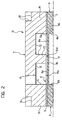
- a spacer ring 9 (see Figure 2) is arranged above the flat surface 8a of the metal body 2, made of a material which forms a poor magnetic conductor.
- the spacer ring 9 can be made, for example, of a paramagnetic or diamagnetic material, such as beryllium copper or a plastics material such as the resins known by the trade names Kapton or Ryton.
- the spacer ring 9 has a calibrated uniform thickness and a central hole 9a which leaves the thin wall 8c of the metal body 8 exposed.
- An inductor is arranged over the spacer ring 9.
- This inductor includes a body 11 of ferromagnetic material, preferably a ferrite, having a flat lower surface or face 11a which rests on the spacer ring 9 and in part faces the wall 8c of the body 8, through the hole in the ring 9.
- An annular recess 12 is formed in the flat face 11a of the ferromagnetic body 11 which defines an essentially cylindrical central core 13 and a surrounding peripheral annular sleeve 14 in the body 11.
- a spool 15 carrying a winding 16 is arranged around the core 13 in the said annular recess. The spool and the winding are not shown in Figure 2 in order to avoid crowding the drawing.
- the free end face 13a of the core 13 is separated from the central portion of the upper surface 8a of the wall 8c of the body 8 by an air gap 17 (Figure 2) the height of which depends on the thickness of the said spacer ring.
- the inductance measurable between the ends of the winding 16 depends not only on the characteristics of the winding itself but also on those of the magnetic circuit constituted by the body 8 and the body 11, and on the size of the air gap 17.
- the ends of the winding 16, indicated 18, extend through a hole 19 in the body 11 of ferromagnetic material.
- An essentially tubular shaped support body 20 extends above and around the said body 11, forming an internal annular wall 21 around a central aperture 22.
- This circuit is arranged to convert the operating variations in the inductance of the inductor into a signal having a correspondingly variable characteristic, such as its amplitude or frequency.
- the body 11 of ferromagnetic material and the metal body 8 are axially clamped to each other by a plurality of clamps 25 which lie in longitudinal grooves 26 within the support member 20.
- the clamps 25 are conveniently constituted by shaped arms extending from the periphery of a ring 27 held in a housing 28 formed in the upper surface of the ferromagnetic body 11.
- a metal screen indicated 29 and of essentially inverted cup-shape, is mounted inside the upper body 3, around and above the support element 20.
- the screen 28 In addition to acting as a barrier to electromagnetic interference, by means of portions of its side wall which are offset inwardly, such as that indicated 29a in Figure 1, the screen 28 also holds the support element 20 in its axial position.
- Openings 30 are formed in the upper portion of the screen 29 with respective annular screening capacitors 31 arranged therein with corresponding connecting conductors 32 passing through them, for connecting the electronic circuit 24 to a connector plate 33 arranged in the upper portion of the support body 3.
- Terminals 34 are connected to the said plate and extend through an upper transverse wall of the support body 3 to project into a seat 35 formed in the upper portion of the body 3 to act as a connector for external circuits.
- the pressure of the fluid introduced through the aperture 7 in the lower body 2 causes an elastic deformation of the wall 8c of the metal body 8 and a corresponding variation in the air gap 17 between the said wall and the core 13 of the inductor, and thus in the characteristics of the magnetic circuit. There is, therefore, a measurable variation in the inductance across the terminals of the winding 16.
- the circuit 24 converts the inductance of the inductor into an electric signal a characteristic of which, such as its amplitude or frequency, is indicative of the pressure of the fluid.
- the magnitude of the air gap 17 at rest (atmospheric pressure at the inlet 7) can be made accurately and repeatably, thanks to the relative ease of forming the facing flat surfaces 8a of the metal body 8 and 11a of the ferromagnetic body 11, as well as the ease with which it is possible to calibrate the thickness of the spacer ring 9.
- the pressure transducer of the invention can be provided for transducing variable pressure in a wide range of fields, according to the desired application.
- transducers for detecting pressures varying between 0 and 4.5 bar for use in the boilers of domestic heating systems, or for pressures varying between 0 and around 30 bar for use in industrial-type heating systems, or in climate control systems, in particular for motor vehicles.
- the pressure transducer of the invention is also suitable for use at higher pressures, for example for pressures variable between 0 and 120 bar, for use in gasoline direct injection (GDI) systems of internal combustion engines for motor vehicles, or even for pressures variable between 0 and around 2000 bar for direct Diesel injection (DDI) systems.
- GDI gasoline direct injection
- DAI direct Diesel injection
- the wall 8c of the metal body 8 could have a diameter of between 8 and 15mm and a thickness between 0.3 and 0.5mm.
- the air gap 17 between this wall and the core 13 of the transducer could thus vary between 0.05 and 0.3mm and the ferrite used for the body 11 of the transducer should be, for convenience, a ferrite having an initial permeability value of ⁇ i ⁇ 500, such as ferrites sold by Philips under the code 3C85.
- FIG. 3 shows a variant of the pressure transducer of the invention.
- parts and elements which have already been described are indicated by the same reference numbers.
- the upper body 3 is directly clamped to the radial flange 4 of the lower metal body 2 by integral extensions 3a having transverse teeth 3b on their lower portion for snap-engagement under the said flange.
- the spacer ring 9 is made in one piece with the spool 15 carrying the winding 16 of the inductor. This arrangement could, in fact, also be applied to the device described earlier with reference to Figure 1.
- a further characteristic of the device of Figure 3 is that the electronic circuit 24, to which the winding 16 is connected, is carried in part by a support plate 23 mounted inside the annular cavity or recess 12 in the ferromagnetic body 11.
- the plate 23 is connected to projections 15a of the flange of the spool 15 facing away from the membrane 8c.
- the portion of circuit carried by the board 23 is connected to the remaining portion of the circuit 24 which is carried by another board 33, arranged above the ferromagnetic element 11.
- Conductor members 40 extending through the ferromagnetic element 11, interconnect the two portions of the electronic circuit 24.
- clamps 25, which hold the ferromagnetic element 11 and the metal body 8 together axially, have respective support projections 25a fixed to the upper circuit board 33.
- Figure 4 shows a further variant, similar to that described with reference to Figure 3. Also in Figure 4, parts and elements already described have been given the same reference numbers.
- the entire electronic circuit 24 is carried by a circuit board 23 housed in the annular recess 12 in the ferromagnetic element 11.
- the element 11 of ferromagnetic material acts itself as an effective screen against interference for the circuits housed within it.
- the output terminals of the circuit 24 are conveniently coupled through corresponding earthed condensers of an SMD type, in order to filter out interference.
Landscapes
- Physics & Mathematics (AREA)
- General Physics & Mathematics (AREA)
- Measuring Fluid Pressure (AREA)
- Measuring Pulse, Heart Rate, Blood Pressure Or Blood Flow (AREA)
- Magnetic Heads (AREA)
- Supply Devices, Intensifiers, Converters, And Telemotors (AREA)
Applications Claiming Priority (3)
| Application Number | Priority Date | Filing Date | Title |
|---|---|---|---|
| IT1998TO001048A IT1303602B1 (it) | 1998-12-15 | 1998-12-15 | Trasduttore induttivo di pressione. |
| ITTO981048 | 1998-12-15 | ||
| PCT/EP1999/009862 WO2000036384A1 (en) | 1998-12-15 | 1999-12-13 | An inductive pressure transducer |
Publications (2)
| Publication Number | Publication Date |
|---|---|
| EP1144974A1 EP1144974A1 (en) | 2001-10-17 |
| EP1144974B1 true EP1144974B1 (en) | 2003-03-26 |
Family
ID=11417249
Family Applications (1)
| Application Number | Title | Priority Date | Filing Date |
|---|---|---|---|
| EP99963513A Expired - Lifetime EP1144974B1 (en) | 1998-12-15 | 1999-12-13 | An inductive pressure transducer |
Country Status (14)
| Country | Link |
|---|---|
| US (1) | US6581470B1 (it) |
| EP (1) | EP1144974B1 (it) |
| JP (1) | JP2002532708A (it) |
| KR (1) | KR20010105312A (it) |
| CN (1) | CN1334917A (it) |
| AT (1) | ATE235678T1 (it) |
| AU (1) | AU1978100A (it) |
| BR (1) | BR9917028A (it) |
| CA (1) | CA2354262C (it) |
| DE (1) | DE69906382T2 (it) |
| ES (1) | ES2194542T3 (it) |
| IT (1) | IT1303602B1 (it) |
| RU (1) | RU2001119442A (it) |
| WO (1) | WO2000036384A1 (it) |
Families Citing this family (7)
| Publication number | Priority date | Publication date | Assignee | Title |
|---|---|---|---|---|
| JP4403932B2 (ja) * | 2004-09-14 | 2010-01-27 | 株式会社デンソー | 電磁弁一体型圧力センサの取付構造 |
| DE102007053859A1 (de) * | 2007-11-09 | 2009-05-14 | Endress + Hauser Gmbh + Co. Kg | Druck-Messeinrichtung |
| CN100526823C (zh) * | 2008-02-23 | 2009-08-12 | 中国科学院合肥物质科学研究院 | 电涡流空调冷媒线性传感器及其工作方法 |
| JP2012215153A (ja) * | 2011-04-01 | 2012-11-08 | Denso Corp | 電子部品装置 |
| US8459125B2 (en) * | 2011-08-01 | 2013-06-11 | Honeywell International Inc. | Pressure sensor assembly |
| CN105731204A (zh) * | 2016-03-24 | 2016-07-06 | 周玉红 | 一种垂直电梯应力感应器 |
| DE202016008549U1 (de) * | 2016-11-04 | 2018-07-31 | Nidec Corporation | Sammelschieneneinheit für einen Elektromotor |
Family Cites Families (11)
| Publication number | Priority date | Publication date | Assignee | Title |
|---|---|---|---|---|
| US3680387A (en) * | 1970-12-02 | 1972-08-01 | Beckman Instruments Inc | Differential pressure transducer |
| DE3035186A1 (de) * | 1980-09-18 | 1982-04-29 | Robert Bosch Gmbh, 7000 Stuttgart | Induktiver drucksensor |
| US4395916A (en) * | 1981-12-30 | 1983-08-02 | Combustion Engineering, Inc. | Arrangement for sealing a reactive element within a fluid pressure transducer |
| JPS59174729A (ja) * | 1983-03-25 | 1984-10-03 | Seiko Instr & Electronics Ltd | 圧力センサ− |
| FR2555743B1 (fr) * | 1983-11-25 | 1986-04-11 | Sereg Soc | Capteur inductif de pression differentielle |
| JPS61132728U (it) * | 1985-02-07 | 1986-08-19 | ||
| JPH04259837A (ja) * | 1991-02-15 | 1992-09-16 | Honda Motor Co Ltd | 圧力センサ |
| JPH05340831A (ja) * | 1992-02-26 | 1993-12-24 | Nippondenso Co Ltd | 圧力センサ |
| US5492017A (en) * | 1994-02-14 | 1996-02-20 | Abb Vetco Gray Inc. | Inductive pressure transducer |
| JP3209655B2 (ja) * | 1995-03-31 | 2001-09-17 | エヌオーケー株式会社 | 圧力センサ |
| JP3688063B2 (ja) * | 1996-08-01 | 2005-08-24 | 長野計器株式会社 | 析出硬化型ステンレス鋼製成形体の製造方法 |
-
1998
- 1998-12-15 IT IT1998TO001048A patent/IT1303602B1/it active IP Right Grant
-
1999
- 1999-12-13 KR KR1020017007486A patent/KR20010105312A/ko not_active Withdrawn
- 1999-12-13 US US09/868,032 patent/US6581470B1/en not_active Expired - Fee Related
- 1999-12-13 DE DE69906382T patent/DE69906382T2/de not_active Expired - Lifetime
- 1999-12-13 JP JP2000588578A patent/JP2002532708A/ja active Pending
- 1999-12-13 EP EP99963513A patent/EP1144974B1/en not_active Expired - Lifetime
- 1999-12-13 RU RU2001119442/28A patent/RU2001119442A/ru not_active Application Discontinuation
- 1999-12-13 AT AT99963513T patent/ATE235678T1/de not_active IP Right Cessation
- 1999-12-13 BR BR9917028-0A patent/BR9917028A/pt not_active IP Right Cessation
- 1999-12-13 CN CN99816083A patent/CN1334917A/zh active Pending
- 1999-12-13 CA CA002354262A patent/CA2354262C/en not_active Expired - Fee Related
- 1999-12-13 ES ES99963513T patent/ES2194542T3/es not_active Expired - Lifetime
- 1999-12-13 AU AU19781/00A patent/AU1978100A/en not_active Abandoned
- 1999-12-13 WO PCT/EP1999/009862 patent/WO2000036384A1/en not_active Ceased
Also Published As
| Publication number | Publication date |
|---|---|
| US6581470B1 (en) | 2003-06-24 |
| EP1144974A1 (en) | 2001-10-17 |
| CA2354262C (en) | 2009-04-14 |
| CA2354262A1 (en) | 2000-06-22 |
| IT1303602B1 (it) | 2000-11-14 |
| DE69906382D1 (de) | 2003-04-30 |
| RU2001119442A (ru) | 2003-06-27 |
| ITTO981048A0 (it) | 1998-12-15 |
| ATE235678T1 (de) | 2003-04-15 |
| BR9917028A (pt) | 2001-09-25 |
| JP2002532708A (ja) | 2002-10-02 |
| WO2000036384A1 (en) | 2000-06-22 |
| DE69906382T2 (de) | 2003-10-23 |
| ITTO981048A1 (it) | 2000-06-15 |
| AU1978100A (en) | 2000-07-03 |
| CN1334917A (zh) | 2002-02-06 |
| KR20010105312A (ko) | 2001-11-28 |
| ES2194542T3 (es) | 2003-11-16 |
Similar Documents
| Publication | Publication Date | Title |
|---|---|---|
| US7124645B2 (en) | Magnetic-inductive measuring device for flowing substances and method for its production | |
| CN103797338B (zh) | 磁感应流量测量装置 | |
| KR101846560B1 (ko) | 힘 센서 조립체 및 힘 센서 조립체의 조립 방법 | |
| CN103765169B (zh) | 磁感应流量测量装置 | |
| RU2090850C1 (ru) | Датчик давления с выемкой для разгрузки от механических напряжений | |
| KR101600089B1 (ko) | 수직형 압력 센서 | |
| EP1144974B1 (en) | An inductive pressure transducer | |
| US10278288B2 (en) | Inductive sensor for shock absorber | |
| WO2009037561A2 (en) | Inductive position sensor | |
| EP1947434A2 (en) | Magnetostrictive strain sensor | |
| KR20110088173A (ko) | 수직형 압력 센서 | |
| US4965777A (en) | Very-high-pressure transducer, particularly for detecting the pressure of a hydraulic fluid | |
| US5867022A (en) | Inductive angle-of-rotation sensor having rotatable magnetically conductive element within single winding coil | |
| EP2724133A1 (de) | Drucksensoranordnung zur erfassung eines drucks eines fluiden mediums in einem messraum | |
| GB2125167A (en) | Electrical fluid pressure transducer diaphragms | |
| EP0169633A2 (en) | Compact displacement transducer | |
| JP2008185334A (ja) | 圧力センサ | |
| US20100134123A1 (en) | Sensor system having a magnetoelastic deformation element | |
| US7511476B2 (en) | Electromagnetic sensor systems and methods of use thereof | |
| JP2001004476A (ja) | 非共振型ノックセンサ | |
| JPH01250732A (ja) | 圧力センサ | |
| JP2004325369A (ja) | 電磁流量計 | |
| JPH056506Y2 (it) | ||
| JPH0355875Y2 (it) | ||
| JP3391022B2 (ja) | 電磁流量計 |
Legal Events
| Date | Code | Title | Description |
|---|---|---|---|
| PUAI | Public reference made under article 153(3) epc to a published international application that has entered the european phase |
Free format text: ORIGINAL CODE: 0009012 |
|
| 17P | Request for examination filed |
Effective date: 20010710 |
|
| AK | Designated contracting states |
Kind code of ref document: A1 Designated state(s): AT BE CH CY DE DK ES FI FR GB GR IE IT LI LU MC NL PT SE |
|
| AX | Request for extension of the european patent |
Free format text: AL;LT;LV;MK;RO;SI |
|
| GRAG | Despatch of communication of intention to grant |
Free format text: ORIGINAL CODE: EPIDOS AGRA |
|
| 17Q | First examination report despatched |
Effective date: 20020527 |
|
| GRAG | Despatch of communication of intention to grant |
Free format text: ORIGINAL CODE: EPIDOS AGRA |
|
| GRAH | Despatch of communication of intention to grant a patent |
Free format text: ORIGINAL CODE: EPIDOS IGRA |
|
| GRAH | Despatch of communication of intention to grant a patent |
Free format text: ORIGINAL CODE: EPIDOS IGRA |
|
| GRAA | (expected) grant |
Free format text: ORIGINAL CODE: 0009210 |
|
| AK | Designated contracting states |
Designated state(s): AT BE CH CY DE DK ES FI FR GB GR IE IT LI LU MC NL PT SE |
|
| PG25 | Lapsed in a contracting state [announced via postgrant information from national office to epo] |
Ref country code: LI Free format text: LAPSE BECAUSE OF FAILURE TO SUBMIT A TRANSLATION OF THE DESCRIPTION OR TO PAY THE FEE WITHIN THE PRESCRIBED TIME-LIMIT Effective date: 20030326 Ref country code: GR Free format text: LAPSE BECAUSE OF FAILURE TO SUBMIT A TRANSLATION OF THE DESCRIPTION OR TO PAY THE FEE WITHIN THE PRESCRIBED TIME-LIMIT Effective date: 20030326 Ref country code: CH Free format text: LAPSE BECAUSE OF FAILURE TO SUBMIT A TRANSLATION OF THE DESCRIPTION OR TO PAY THE FEE WITHIN THE PRESCRIBED TIME-LIMIT Effective date: 20030326 Ref country code: BE Free format text: LAPSE BECAUSE OF FAILURE TO SUBMIT A TRANSLATION OF THE DESCRIPTION OR TO PAY THE FEE WITHIN THE PRESCRIBED TIME-LIMIT Effective date: 20030326 |
|
| REG | Reference to a national code |
Ref country code: GB Ref legal event code: FG4D |
|
| REG | Reference to a national code |
Ref country code: CH Ref legal event code: EP |
|
| REG | Reference to a national code |
Ref country code: SE Ref legal event code: TRGR |
|
| REF | Corresponds to: |
Ref document number: 69906382 Country of ref document: DE Date of ref document: 20030430 Kind code of ref document: P |
|
| REG | Reference to a national code |
Ref country code: IE Ref legal event code: FG4D |
|
| PG25 | Lapsed in a contracting state [announced via postgrant information from national office to epo] |
Ref country code: DK Free format text: LAPSE BECAUSE OF FAILURE TO SUBMIT A TRANSLATION OF THE DESCRIPTION OR TO PAY THE FEE WITHIN THE PRESCRIBED TIME-LIMIT Effective date: 20030626 |
|
| PG25 | Lapsed in a contracting state [announced via postgrant information from national office to epo] |
Ref country code: PT Free format text: LAPSE BECAUSE OF FAILURE TO SUBMIT A TRANSLATION OF THE DESCRIPTION OR TO PAY THE FEE WITHIN THE PRESCRIBED TIME-LIMIT Effective date: 20030630 |
|
| REG | Reference to a national code |
Ref country code: CH Ref legal event code: PL |
|
| PGFP | Annual fee paid to national office [announced via postgrant information from national office to epo] |
Ref country code: FI Payment date: 20031105 Year of fee payment: 5 |
|
| ET | Fr: translation filed | ||
| REG | Reference to a national code |
Ref country code: ES Ref legal event code: FG2A Ref document number: 2194542 Country of ref document: ES Kind code of ref document: T3 |
|
| PGFP | Annual fee paid to national office [announced via postgrant information from national office to epo] |
Ref country code: NL Payment date: 20031117 Year of fee payment: 5 |
|
| PGFP | Annual fee paid to national office [announced via postgrant information from national office to epo] |
Ref country code: IE Payment date: 20031120 Year of fee payment: 5 |
|
| PG25 | Lapsed in a contracting state [announced via postgrant information from national office to epo] |
Ref country code: CY Free format text: LAPSE BECAUSE OF FAILURE TO SUBMIT A TRANSLATION OF THE DESCRIPTION OR TO PAY THE FEE WITHIN THE PRESCRIBED TIME-LIMIT Effective date: 20031213 |
|
| PGFP | Annual fee paid to national office [announced via postgrant information from national office to epo] |
Ref country code: LU Payment date: 20031215 Year of fee payment: 5 |
|
| PG25 | Lapsed in a contracting state [announced via postgrant information from national office to epo] |
Ref country code: MC Free format text: LAPSE BECAUSE OF NON-PAYMENT OF DUE FEES Effective date: 20031231 |
|
| PLBE | No opposition filed within time limit |
Free format text: ORIGINAL CODE: 0009261 |
|
| STAA | Information on the status of an ep patent application or granted ep patent |
Free format text: STATUS: NO OPPOSITION FILED WITHIN TIME LIMIT |
|
| 26N | No opposition filed |
Effective date: 20031230 |
|
| PG25 | Lapsed in a contracting state [announced via postgrant information from national office to epo] |
Ref country code: FI Free format text: LAPSE BECAUSE OF NON-PAYMENT OF DUE FEES Effective date: 20041204 |
|
| PG25 | Lapsed in a contracting state [announced via postgrant information from national office to epo] |
Ref country code: LU Free format text: LAPSE BECAUSE OF NON-PAYMENT OF DUE FEES Effective date: 20041213 Ref country code: IE Free format text: LAPSE BECAUSE OF NON-PAYMENT OF DUE FEES Effective date: 20041213 |
|
| PG25 | Lapsed in a contracting state [announced via postgrant information from national office to epo] |
Ref country code: NL Free format text: LAPSE BECAUSE OF NON-PAYMENT OF DUE FEES Effective date: 20050701 |
|
| NLV4 | Nl: lapsed or anulled due to non-payment of the annual fee |
Effective date: 20050701 |
|
| REG | Reference to a national code |
Ref country code: IE Ref legal event code: MM4A |
|
| PGFP | Annual fee paid to national office [announced via postgrant information from national office to epo] |
Ref country code: AT Payment date: 20081106 Year of fee payment: 10 |
|
| PGFP | Annual fee paid to national office [announced via postgrant information from national office to epo] |
Ref country code: SE Payment date: 20081211 Year of fee payment: 10 |
|
| EUG | Se: european patent has lapsed | ||
| PG25 | Lapsed in a contracting state [announced via postgrant information from national office to epo] |
Ref country code: AT Free format text: LAPSE BECAUSE OF NON-PAYMENT OF DUE FEES Effective date: 20091213 |
|
| PG25 | Lapsed in a contracting state [announced via postgrant information from national office to epo] |
Ref country code: SE Free format text: LAPSE BECAUSE OF NON-PAYMENT OF DUE FEES Effective date: 20091214 |
|
| PGFP | Annual fee paid to national office [announced via postgrant information from national office to epo] |
Ref country code: ES Payment date: 20121120 Year of fee payment: 14 Ref country code: IT Payment date: 20121214 Year of fee payment: 14 Ref country code: GB Payment date: 20121220 Year of fee payment: 14 |
|
| PGFP | Annual fee paid to national office [announced via postgrant information from national office to epo] |
Ref country code: FR Payment date: 20130123 Year of fee payment: 14 Ref country code: DE Payment date: 20130228 Year of fee payment: 14 |
|
| REG | Reference to a national code |
Ref country code: DE Ref legal event code: R119 Ref document number: 69906382 Country of ref document: DE |
|
| GBPC | Gb: european patent ceased through non-payment of renewal fee |
Effective date: 20131213 |
|
| REG | Reference to a national code |
Ref country code: FR Ref legal event code: ST Effective date: 20140829 |
|
| REG | Reference to a national code |
Ref country code: DE Ref legal event code: R119 Ref document number: 69906382 Country of ref document: DE Effective date: 20140701 |
|
| PG25 | Lapsed in a contracting state [announced via postgrant information from national office to epo] |
Ref country code: DE Free format text: LAPSE BECAUSE OF NON-PAYMENT OF DUE FEES Effective date: 20140701 |
|
| PG25 | Lapsed in a contracting state [announced via postgrant information from national office to epo] |
Ref country code: FR Free format text: LAPSE BECAUSE OF NON-PAYMENT OF DUE FEES Effective date: 20131231 Ref country code: GB Free format text: LAPSE BECAUSE OF NON-PAYMENT OF DUE FEES Effective date: 20131213 |
|
| REG | Reference to a national code |
Ref country code: ES Ref legal event code: FD2A Effective date: 20150327 |
|
| PG25 | Lapsed in a contracting state [announced via postgrant information from national office to epo] |
Ref country code: ES Free format text: LAPSE BECAUSE OF NON-PAYMENT OF DUE FEES Effective date: 20131214 |
|
| PG25 | Lapsed in a contracting state [announced via postgrant information from national office to epo] |
Ref country code: IT Free format text: LAPSE BECAUSE OF NON-PAYMENT OF DUE FEES Effective date: 20131231 |
|
| PG25 | Lapsed in a contracting state [announced via postgrant information from national office to epo] |
Ref country code: IT Free format text: LAPSE BECAUSE OF NON-PAYMENT OF DUE FEES Effective date: 20131213 |