EP1142659A1 - Stützlager für Rollen - Google Patents
Stützlager für Rollen Download PDFInfo
- Publication number
- EP1142659A1 EP1142659A1 EP01250118A EP01250118A EP1142659A1 EP 1142659 A1 EP1142659 A1 EP 1142659A1 EP 01250118 A EP01250118 A EP 01250118A EP 01250118 A EP01250118 A EP 01250118A EP 1142659 A1 EP1142659 A1 EP 1142659A1
- Authority
- EP
- European Patent Office
- Prior art keywords
- bearing
- bearing block
- roller
- support
- pin
- Prior art date
- Legal status (The legal status is an assumption and is not a legal conclusion. Google has not performed a legal analysis and makes no representation as to the accuracy of the status listed.)
- Withdrawn
Links
- 239000002826 coolant Substances 0.000 claims abstract description 5
- 229910000831 Steel Inorganic materials 0.000 claims description 5
- 239000010959 steel Substances 0.000 claims description 5
- 230000000295 complement effect Effects 0.000 claims description 4
- 239000004519 grease Substances 0.000 claims description 3
- 238000009749 continuous casting Methods 0.000 claims description 2
- 230000000903 blocking effect Effects 0.000 claims 1
- 238000009434 installation Methods 0.000 claims 1
- 238000001816 cooling Methods 0.000 description 10
- 238000005096 rolling process Methods 0.000 description 6
- 238000007789 sealing Methods 0.000 description 5
- 238000010276 construction Methods 0.000 description 2
- 239000000314 lubricant Substances 0.000 description 2
- 230000005855 radiation Effects 0.000 description 2
- 238000005266 casting Methods 0.000 description 1
- 238000005336 cracking Methods 0.000 description 1
- 238000006073 displacement reaction Methods 0.000 description 1
- 238000012423 maintenance Methods 0.000 description 1
- 238000004519 manufacturing process Methods 0.000 description 1
- 239000000565 sealant Substances 0.000 description 1
- 238000000926 separation method Methods 0.000 description 1
- 125000006850 spacer group Chemical group 0.000 description 1
Images

Classifications
-
- B—PERFORMING OPERATIONS; TRANSPORTING
- B22—CASTING; POWDER METALLURGY
- B22D—CASTING OF METALS; CASTING OF OTHER SUBSTANCES BY THE SAME PROCESSES OR DEVICES
- B22D11/00—Continuous casting of metals, i.e. casting in indefinite lengths
- B22D11/12—Accessories for subsequent treating or working cast stock in situ
- B22D11/128—Accessories for subsequent treating or working cast stock in situ for removing
- B22D11/1287—Rolls; Lubricating, cooling or heating rolls while in use
Definitions
- the invention relates to a support bearing for rollers, in particular strand guide rollers in a continuous steel caster for slabs according to the preamble of Claim 1.
- the second bearing is preferably designed as a spherical bearing, the Inner ring on the pin and its outer ring on the inside of the supports adjacent roller section.
- a disadvantage of this known Arrangement is the complex construction of the support bearing with many items to be kept. Furthermore, it is not possible with this construction an offset of two adjacent, but differently worn and to compensate for reworked roller sections.
- Another disadvantage is that the Cross section for the collar-shaped pin must be chosen large, so that the bearing dimensions are large. This in turn leads to big ones Reel diameters, but with regard to the support possibility of the transporting goods are unfavorable.
- the object of the invention is in particular a support bearing for rollers Strand guide rolls in a steel continuous caster for slabs to indicate that is small and has a small gap for two adjacent roles. Another task is to easily offset two to compensate for differently worn adjacent roles.
- the bearing block has at least one pin which the roller bearing is arranged and the complementary in an axially aligned Recess of the role protrudes so far that at least the rolling bearing through the Roll is completely covered.
- the rolling bearing is known as toroidal Roller bearings trained. This design is better known under the brand name Carb from SKF.
- the proposed arrangement has the advantage that the structure very simple and the number of parts to be kept small. With that the Maintenance effort reduced.
- the support bearing can be made using toroidal roller bearings can be designed so that the diameter of the Role is also low.
- Another advantage is that both toroidal roller bearings allows an axial displacement as well as an inclination of the rollers. This Mobility is particularly important when transporting hot slabs because on the one hand the rollers expand under the influence of heat and on the other hand they expand also bend through the load of the slabs.
- the bearing block is in the transverse plane divided symmetrically and both mirrored and contiguous Bearing bracket elements are by fasteners, preferably screws blocked together.
- the screws extend through in both Bearing block elements arranged holes, whose inner diameter is larger than the shaft diameter of the screws.
- the bearing block can also be cooled. This is in the bearing block or at least one channel for the supply and discharge in the respective bracket element a coolant provided. This arrangement is independent of the The roll can be cooled, but can also be integrated with it.
- roller bearing block or bearing block element is preferably a grease lubricant Seal arranged.
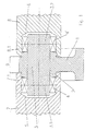
- Figure 1 is a longitudinal section of a first embodiment of a Support bearing designed according to the invention is shown. It is this Embodiment of a one-piece bearing block 1 with a transverse Bore 2 through which a pin formed as a pin 3 is pressed.
- a roller bearing 4, 4 ' On the over the bearing block 1 projecting pin element 3.1 or 3.2 is a roller bearing 4, 4 'arranged.
- the respective roller bearing 4, 4 ' is preferably a small one toroidal roller bearing (carb) formed.
- the pin element 3.1 or 3.2 protrudes into a complementary recess 5, 6 of the respective roller 7, 8 into it.
- the depth of the Recess 5, 6 is selected such that the end region 7.1, 8.1 of the respective roller 7, 8 extends at least over the roller bearing 4, 4 '.
- the necessary seals are not shown in this figure for the rolling bearing, as well as the possibility of
- the proposed arrangement allowed the required gap 9 between the two adjacent rollers 7, 8 is small. While she is usually 150mm to 200mm, it can in this way to a value ⁇ Can be reduced by 50mm. Another advantage is that the sensitive roller bearings 4, 4 'in the case of hot slab transport before direct heat radiation are protected, especially since the rollers 7, 8 are usually also cooled.
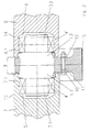
- Figure 2 shows a second embodiment, the same for the same parts Reference numerals have been chosen.
- the bearing block is in the Transverse plane divided symmetrically and has two mirror images Bearing block elements 1.1, 1.2.
- the pin element 3.1 or 3.2 is, as here shown, integral part of the respective bracket element 1.1, 1.2, can but also, as shown in Figure 1, as a bolt in a corresponding bore of the Bearing block element 1.1, 1.2 be pressed.
- the two bracket elements 1.1, 1.2 are locked together with screws 10 (only one shown here).
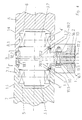
- Figure 3 shows in a longitudinal section a comparable embodiment as Figure 1, but with cooling and sealing.
- the bearing block 1 has at least one cooling channel 16 for the supply and a cooling channel 17 for the removal of the coolant.
- an annular channel 18 is provided for the Cooling of the bearing block area most exposed to heat radiation.
- a seal 19.1.19.2 is arranged in the contact area between the respective end area 7.1.8.1 of the roller 7.8 and the bearing block 1. she is to prevent dirt from getting into the rolling bearing area from the outside.
- FIG. 4 shows a comparable embodiment as shown in FIG. 2, but with Cooling and sealing.
- each bracket element 1.1.1.2 has one Cooling channel 16.1,16.2 for the supply and one cooling channel 17.1,17.2 for the removal of the Coolant.
- An annular channel 18.1, 18.2 is provided in the jacket area.
- the Contact area between the bearing block element 1.1.1.2 and the end area 7.1.8.2 each roller 7,8 is provided with a seal 19.1,19.2.
- A is indicated here Channel 19.1, 19.2 leading channel 20.1, 20.2 to grease as a sealant to be able to deliver later.
Landscapes
- Engineering & Computer Science (AREA)
- Mechanical Engineering (AREA)
- Rolling Contact Bearings (AREA)
- Rolls And Other Rotary Bodies (AREA)
Abstract
Description
- Figur 1
- in einem Längsschnitt eine erste Ausführungsform eines erfindungsgemäß ausgebildeten Stützlagers
- Figur 2
- wie Fig. 1 eine zweite Ausführungsform
- Figur 3
- wie Figur 1, aber mit Kühlung und Abdichtung
- Figur 4
- wie Figur 2, aber mit Kühlung und Abdichtung
Claims (11)
- Stützlager für Rollen insbesondere Strangführungsrollen in einer Stahl-Stranggießanlage für Brammen mit einem Lagerbock und auf Zapfen angeordnete Wälzlager,
dadurch gekennzeichnet, dass der Lagerbock (1, 1.1, 1.2) mindestens einen Zapfen (3, 3.1, 3.2) aufweist, auf dem das Wälzlager (4, 4') angeordnet ist und der Zapfen (3, 3.1, 3.2) in eine achsgleich liegende komplementäre Ausnehmung (5, 6) der Rolle (7, 8) soweit hineinragt, dass mindestens das Wälzlager (4, 4') durch die Rolle (7, 8) vollständig überdeckt ist. - Stützlager nach Anspruch 1,
dadurch gekennzeichnet, dass für koaxial benachbart gelagerte und unabhängig voneinander drehbare Rollen (7, 8) der Lagerbock (1) je einen nach rechts und nach links sich erstreckenden Zapfen (3.1, 3.2) aufweist. - Stützlager nach Anspruch 1,
dadurch gekennzeichnet, dass der Zapfen (3.1, 3.2) integraler Bestandteil des Lagerbockes (1) ist. - Stützlager nach Anspruch 1 oder 2,
dadurch gekennzeichnet, dass der Zapfen (3) als separates Teil in einer Bohrung (2) des Lagerbockes (1) eingepresst ist. - Stützlager nach einem der Ansprüche 1 bis 2,
dadurch gekennzeichnet, dass der Lagerbock in der Querebene symmetrisch geteilt ist und beide spiegelbildlich ausgebildeten und aneinander liegenden Lagerbockelemente (1.1, 1.2) durch Befestigungselemente (10) miteinander verblockt sind. - Stützlager nach Anspruch 5,
dadurch gekennzeichnet, dass zur Verblockung mehrere über den Umfang verteilt angeordnete Schrauben (10) vorgesehen sind, die sich durch in beiden Lagerbockelementen (1.1, 1.2) angeordnete Bohrungen (11, 12) erstrecken, deren Innendurchmesser größer ist als der Schaftdurchmesser der Schrauben (10). - Stützlager nach einem der Ansprüche 1 bis 6,
dadurch gekennzeichnet, dass der Lagerbock (1) bzw. das Lagerbockelement (1.1, 1.2) mit mindestens einem Kanal (16,16.1;16.2;17;17.1;17.2) für die Zu- und Abfuhr eines Kühlmittels versehen ist. - Stützlager nach einem der Ansprüche 1 bis 7,
dadurch gekennzeichnet, dass die Rolle (7, 8) sich über das Wälzlager (4, 4') hinweg bis in den Anfangsbereich des Lagerbockes (1) bzw. Lagerbockelementes (1.1, 1.2) erstreckt. - Stützlager nach Anspruch 8,
dadurch gekennzeichnet, dass im Kontaktbereich Rolle (7, 8)- Lagerbock (1) bzw. Lagerbockelement (1.1, 1.2) eine Dichtung (19.1,19.2) angeordnet ist. - Stützlager nach Anspruch 9,
dadurch gekennzeichnet, dass die Dichtung (19.1,19.2) fettstoffgeschmiert ist. - Stützlager nach einem der Ansprüche 1-10,
dadurch gekennzeichnet, dass das Wälzlager (4,4') als toroidales Rollenlager ausgebildet ist.
Applications Claiming Priority (2)
| Application Number | Priority Date | Filing Date | Title |
|---|---|---|---|
| DE10018029 | 2000-04-04 | ||
| DE2000118029 DE10018029C2 (de) | 2000-04-04 | 2000-04-04 | Stützlager für Rollen |
Publications (1)
| Publication Number | Publication Date |
|---|---|
| EP1142659A1 true EP1142659A1 (de) | 2001-10-10 |
Family
ID=7638402
Family Applications (1)
| Application Number | Title | Priority Date | Filing Date |
|---|---|---|---|
| EP01250118A Withdrawn EP1142659A1 (de) | 2000-04-04 | 2001-04-03 | Stützlager für Rollen |
Country Status (2)
| Country | Link |
|---|---|
| EP (1) | EP1142659A1 (de) |
| DE (1) | DE10018029C2 (de) |
Cited By (3)
| Publication number | Priority date | Publication date | Assignee | Title |
|---|---|---|---|---|
| AT500327A1 (de) * | 2002-01-24 | 2005-12-15 | Kugelfischer G Schaefer & Co | Wälzlageranordnung für rollen in stranggiessanlagen |
| DE102013213331A1 (de) | 2013-07-08 | 2015-01-08 | Schaeffler Technologies Gmbh & Co. Kg | Stützlagerung, insbesondere Laufrolle |
| US9630247B2 (en) | 2012-07-20 | 2017-04-25 | Sms Concast Ag | Guide roller for guiding a strand in a strand casting system |
Families Citing this family (1)
| Publication number | Priority date | Publication date | Assignee | Title |
|---|---|---|---|---|
| DE10327724B3 (de) * | 2003-06-16 | 2004-09-09 | Mannesmannröhren-Werke Ag | Stützlager für Rollen |
Citations (6)
| Publication number | Priority date | Publication date | Assignee | Title |
|---|---|---|---|---|
| DE1583619A1 (de) * | 1967-12-07 | 1970-08-20 | Demag Ag | Transport- bzw. Stuetzwalze fuer Metall-,insbesondere Stahlstranggiessanlagen |
| FR2291815A1 (fr) * | 1974-11-20 | 1976-06-18 | Lewin Hans | Rouleau pour train de rouleaux, notamment pour installation de coulee continue |
| US4043622A (en) * | 1974-09-13 | 1977-08-23 | John D. Hotchkiss Limited | Bearing assembly |
| FR2545891A1 (fr) * | 1982-10-21 | 1984-11-16 | Kastner Rene | Roulement a rouleaux apte a fonctionner a haute temperature et sans graissage, et rouleaux de machine de coulee continue equipes de tels roulements |
| AT383526B (de) * | 1986-01-30 | 1987-07-10 | Voest Alpine Ag | Strangfuehrungsrolle fuer eine stranggiessanlage |
| DE4227987A1 (de) * | 1992-08-21 | 1994-02-24 | Mannesmann Ag | Wassergekühlte Rolle |
Family Cites Families (1)
| Publication number | Priority date | Publication date | Assignee | Title |
|---|---|---|---|---|
| CH596911A5 (de) * | 1976-09-24 | 1978-03-31 | Concast Ag |
-
2000
- 2000-04-04 DE DE2000118029 patent/DE10018029C2/de not_active Expired - Fee Related
-
2001
- 2001-04-03 EP EP01250118A patent/EP1142659A1/de not_active Withdrawn
Patent Citations (6)
| Publication number | Priority date | Publication date | Assignee | Title |
|---|---|---|---|---|
| DE1583619A1 (de) * | 1967-12-07 | 1970-08-20 | Demag Ag | Transport- bzw. Stuetzwalze fuer Metall-,insbesondere Stahlstranggiessanlagen |
| US4043622A (en) * | 1974-09-13 | 1977-08-23 | John D. Hotchkiss Limited | Bearing assembly |
| FR2291815A1 (fr) * | 1974-11-20 | 1976-06-18 | Lewin Hans | Rouleau pour train de rouleaux, notamment pour installation de coulee continue |
| FR2545891A1 (fr) * | 1982-10-21 | 1984-11-16 | Kastner Rene | Roulement a rouleaux apte a fonctionner a haute temperature et sans graissage, et rouleaux de machine de coulee continue equipes de tels roulements |
| AT383526B (de) * | 1986-01-30 | 1987-07-10 | Voest Alpine Ag | Strangfuehrungsrolle fuer eine stranggiessanlage |
| DE4227987A1 (de) * | 1992-08-21 | 1994-02-24 | Mannesmann Ag | Wassergekühlte Rolle |
Cited By (4)
| Publication number | Priority date | Publication date | Assignee | Title |
|---|---|---|---|---|
| AT500327A1 (de) * | 2002-01-24 | 2005-12-15 | Kugelfischer G Schaefer & Co | Wälzlageranordnung für rollen in stranggiessanlagen |
| AT500327B1 (de) * | 2002-01-24 | 2006-05-15 | Kugelfischer G Schaefer & Co | Wälzlageranordnung für rollen in stranggiessanlagen |
| US9630247B2 (en) | 2012-07-20 | 2017-04-25 | Sms Concast Ag | Guide roller for guiding a strand in a strand casting system |
| DE102013213331A1 (de) | 2013-07-08 | 2015-01-08 | Schaeffler Technologies Gmbh & Co. Kg | Stützlagerung, insbesondere Laufrolle |
Also Published As
| Publication number | Publication date |
|---|---|
| DE10018029A1 (de) | 2002-02-28 |
| DE10018029C2 (de) | 2002-06-27 |
Similar Documents
| Publication | Publication Date | Title |
|---|---|---|
| DE2501956C2 (de) | Vorrichtung zum Stützen, Führen, Biegen bzw. Richten und Verformen eines breiten Gußstranges | |
| AT392523B (de) | Mehrreihiges lager | |
| DE69024616T2 (de) | Zylinder für Einzel- oder Doppelrollenstranggiessvorrichtung | |
| DE2950773A1 (de) | Lager | |
| DE2360188C2 (de) | Drehsicherung an Lagern für die Walzen von Walzgerüsten | |
| DE112007001838T5 (de) | Doppelreihige Kegelrollenlagereinheit | |
| EP0121811B1 (de) | Mehrwalzengerüst | |
| EP0037549B1 (de) | Koaxial benachbart gelagerte Strangführungsrollen in einer Stahl-Stranggiessanlage für Brammen | |
| DE2742570C3 (de) | Führungsrolle für Stahlstrang· gießanlagen | |
| EP3697553A1 (de) | Vorrichtung zum ankuppeln einer kühlmittelzufuhr an eine walze | |
| DE10018029C2 (de) | Stützlager für Rollen | |
| DE2439359A1 (de) | Strangfuehrungsgeruest in einer stranggiessanlage | |
| DE2552969A1 (de) | Fuehrungsrolle fuer stranggussanlagen, mit auf einer mehrfach gelagerten achse angeordneten rollenabschnitten | |
| DE19836537C1 (de) | Strangführungsrolle für eine Metall-, insbesondere Stahlstranggießanlage | |
| EP4408599A1 (de) | Stehlager und produktionsanlage mit solch einem stehlager | |
| AT522298A1 (de) | Kokilleneinheit zum Stranggießen von Metallprodukten sowie Stranggießanlage | |
| EP0879106B1 (de) | Stützrollengerüst für metall-, insbesondere stahlstranggiessanlagen | |
| EP1940572B1 (de) | Strangführungsrolle | |
| DE19506871C1 (de) | Transport- bzw. Stützwalze für Metall- insbesondere Stahlstranggießanlagen | |
| DE69221019T2 (de) | Fussrollen für das Stranggiessen | |
| DE2911624A1 (de) | Lagerung fuer einen rollentreiber einer brammenstranggiessanlage | |
| DE1481159A1 (de) | Transport-,Richt- oder Fuehrungswalze | |
| DE2520813A1 (de) | Lagerkonstruktion fuer leerlaufrollen und zugehoeriges wartungsverfahren | |
| DE20021514U1 (de) | Lageranordnung für eine Walze einer Stranggießanlage | |
| DE10207599B4 (de) | Verfahren zum Erfassen eines Walzenausfalls |
Legal Events
| Date | Code | Title | Description |
|---|---|---|---|
| PUAI | Public reference made under article 153(3) epc to a published international application that has entered the european phase |
Free format text: ORIGINAL CODE: 0009012 |
|
| AK | Designated contracting states |
Kind code of ref document: A1 Designated state(s): AT BE CH CY DE DK ES FI FR GB GR IE IT LI LU MC NL PT SE TR |
|
| AX | Request for extension of the european patent |
Free format text: AL;LT;LV;MK;RO;SI |
|
| 17P | Request for examination filed |
Effective date: 20020225 |
|
| RAP1 | Party data changed (applicant data changed or rights of an application transferred) |
Owner name: MANNESMANNROEHREN-WERKE AG Owner name: THYSSEN KRUPP STAHL AG Owner name: SKF GMBH |
|
| AKX | Designation fees paid |
Free format text: AT BE CH CY DE DK ES FI FR GB GR IE IT LI LU MC NL PT SE TR |
|
| RAP1 | Party data changed (applicant data changed or rights of an application transferred) |
Owner name: SKF GMBH Owner name: THYSSEN KRUPP STAHL AG |
|
| RAP1 | Party data changed (applicant data changed or rights of an application transferred) |
Owner name: SKF GMBH Owner name: THYSSENKRUPP STAHL AG |
|
| 17Q | First examination report despatched |
Effective date: 20050607 |
|
| RAP1 | Party data changed (applicant data changed or rights of an application transferred) |
Owner name: SKF GMBH Owner name: THYSSENKRUPP STEEL AG |
|
| STAA | Information on the status of an ep patent application or granted ep patent |
Free format text: STATUS: THE APPLICATION IS DEEMED TO BE WITHDRAWN |
|
| 18D | Application deemed to be withdrawn |
Effective date: 20051220 |