EP1141638B1 - Isolierbehälter mit einem befüllbarem kühlmodul und einer einrichtung zum zuführen von kühlmedium - Google Patents
Isolierbehälter mit einem befüllbarem kühlmodul und einer einrichtung zum zuführen von kühlmedium Download PDFInfo
- Publication number
- EP1141638B1 EP1141638B1 EP99958183A EP99958183A EP1141638B1 EP 1141638 B1 EP1141638 B1 EP 1141638B1 EP 99958183 A EP99958183 A EP 99958183A EP 99958183 A EP99958183 A EP 99958183A EP 1141638 B1 EP1141638 B1 EP 1141638B1
- Authority
- EP
- European Patent Office
- Prior art keywords
- insulating container
- cooling
- cooling module
- cooling medium
- supply
- Prior art date
- Legal status (The legal status is an assumption and is not a legal conclusion. Google has not performed a legal analysis and makes no representation as to the accuracy of the status listed.)
- Expired - Lifetime
Links
- 238000001816 cooling Methods 0.000 title claims abstract description 104
- 239000002826 coolant Substances 0.000 title claims abstract description 85
- 238000000034 method Methods 0.000 claims abstract description 16
- IJGRMHOSHXDMSA-UHFFFAOYSA-N Atomic nitrogen Chemical compound N#N IJGRMHOSHXDMSA-UHFFFAOYSA-N 0.000 claims description 18
- 229910000831 Steel Inorganic materials 0.000 claims description 15
- 239000010959 steel Substances 0.000 claims description 15
- 239000007788 liquid Substances 0.000 claims description 13
- 238000003860 storage Methods 0.000 claims description 13
- 239000000126 substance Substances 0.000 claims description 10
- 229910052757 nitrogen Inorganic materials 0.000 claims description 9
- 238000009413 insulation Methods 0.000 claims description 5
- 238000004321 preservation Methods 0.000 claims description 3
- 238000002347 injection Methods 0.000 description 14
- 239000007924 injection Substances 0.000 description 14
- CURLTUGMZLYLDI-UHFFFAOYSA-N Carbon dioxide Chemical compound O=C=O CURLTUGMZLYLDI-UHFFFAOYSA-N 0.000 description 8
- 238000005429 filling process Methods 0.000 description 5
- 239000007789 gas Substances 0.000 description 5
- PXHVJJICTQNCMI-UHFFFAOYSA-N Nickel Chemical compound [Ni] PXHVJJICTQNCMI-UHFFFAOYSA-N 0.000 description 4
- 239000001569 carbon dioxide Substances 0.000 description 4
- 229910002092 carbon dioxide Inorganic materials 0.000 description 4
- 235000013305 food Nutrition 0.000 description 4
- 239000011810 insulating material Substances 0.000 description 4
- 229910001220 stainless steel Inorganic materials 0.000 description 4
- 239000010935 stainless steel Substances 0.000 description 4
- 230000001276 controlling effect Effects 0.000 description 3
- 230000005496 eutectics Effects 0.000 description 3
- 239000000463 material Substances 0.000 description 3
- 238000005057 refrigeration Methods 0.000 description 3
- 239000007787 solid Substances 0.000 description 3
- XKRFYHLGVUSROY-UHFFFAOYSA-N Argon Chemical compound [Ar] XKRFYHLGVUSROY-UHFFFAOYSA-N 0.000 description 2
- VYZAMTAEIAYCRO-UHFFFAOYSA-N Chromium Chemical compound [Cr] VYZAMTAEIAYCRO-UHFFFAOYSA-N 0.000 description 2
- 230000008878 coupling Effects 0.000 description 2
- 238000010168 coupling process Methods 0.000 description 2
- 238000005859 coupling reaction Methods 0.000 description 2
- 230000000694 effects Effects 0.000 description 2
- 229910052759 nickel Inorganic materials 0.000 description 2
- 230000001105 regulatory effect Effects 0.000 description 2
- RYGMFSIKBFXOCR-UHFFFAOYSA-N Copper Chemical compound [Cu] RYGMFSIKBFXOCR-UHFFFAOYSA-N 0.000 description 1
- 206010053648 Vascular occlusion Diseases 0.000 description 1
- 238000010521 absorption reaction Methods 0.000 description 1
- 239000003570 air Substances 0.000 description 1
- 239000012080 ambient air Substances 0.000 description 1
- 229910052786 argon Inorganic materials 0.000 description 1
- 230000008901 benefit Effects 0.000 description 1
- 239000012267 brine Substances 0.000 description 1
- 229910052802 copper Inorganic materials 0.000 description 1
- 239000010949 copper Substances 0.000 description 1
- 238000005138 cryopreservation Methods 0.000 description 1
- 230000003247 decreasing effect Effects 0.000 description 1
- 230000001419 dependent effect Effects 0.000 description 1
- 238000009826 distribution Methods 0.000 description 1
- 230000007613 environmental effect Effects 0.000 description 1
- 238000006911 enzymatic reaction Methods 0.000 description 1
- 230000008020 evaporation Effects 0.000 description 1
- 238000001704 evaporation Methods 0.000 description 1
- 239000000945 filler Substances 0.000 description 1
- 239000012530 fluid Substances 0.000 description 1
- 238000007710 freezing Methods 0.000 description 1
- 230000008014 freezing Effects 0.000 description 1
- 230000005484 gravity Effects 0.000 description 1
- 238000003780 insertion Methods 0.000 description 1
- 230000037431 insertion Effects 0.000 description 1
- 230000003993 interaction Effects 0.000 description 1
- 238000002955 isolation Methods 0.000 description 1
- 230000007246 mechanism Effects 0.000 description 1
- 239000007769 metal material Substances 0.000 description 1
- 230000000813 microbial effect Effects 0.000 description 1
- 239000000203 mixture Substances 0.000 description 1
- 230000003647 oxidation Effects 0.000 description 1
- 238000007254 oxidation reaction Methods 0.000 description 1
- 230000008569 process Effects 0.000 description 1
- HPALAKNZSZLMCH-UHFFFAOYSA-M sodium;chloride;hydrate Chemical compound O.[Na+].[Cl-] HPALAKNZSZLMCH-UHFFFAOYSA-M 0.000 description 1
- 238000004781 supercooling Methods 0.000 description 1
- 229960005486 vaccine Drugs 0.000 description 1
Images


Classifications
-
- F—MECHANICAL ENGINEERING; LIGHTING; HEATING; WEAPONS; BLASTING
- F25—REFRIGERATION OR COOLING; COMBINED HEATING AND REFRIGERATION SYSTEMS; HEAT PUMP SYSTEMS; MANUFACTURE OR STORAGE OF ICE; LIQUEFACTION SOLIDIFICATION OF GASES
- F25D—REFRIGERATORS; COLD ROOMS; ICE-BOXES; COOLING OR FREEZING APPARATUS NOT OTHERWISE PROVIDED FOR
- F25D3/00—Devices using other cold materials; Devices using cold-storage bodies
- F25D3/10—Devices using other cold materials; Devices using cold-storage bodies using liquefied gases, e.g. liquid air
- F25D3/105—Movable containers
-
- F—MECHANICAL ENGINEERING; LIGHTING; HEATING; WEAPONS; BLASTING
- F25—REFRIGERATION OR COOLING; COMBINED HEATING AND REFRIGERATION SYSTEMS; HEAT PUMP SYSTEMS; MANUFACTURE OR STORAGE OF ICE; LIQUEFACTION SOLIDIFICATION OF GASES
- F25D—REFRIGERATORS; COLD ROOMS; ICE-BOXES; COOLING OR FREEZING APPARATUS NOT OTHERWISE PROVIDED FOR
- F25D2201/00—Insulation
- F25D2201/10—Insulation with respect to heat
- F25D2201/14—Insulation with respect to heat using subatmospheric pressure
Definitions
- the invention relates to an insulated container with a cooling module and a device for Züschreiben of cooling medium and a method for filling a cooling module in an insulated container.
- insulated container For the transport and storage of perishable goods, in particular of Food, therefore, are containers with a thermally insulating wall (Insulated container) used.
- the insulated containers are usually additional cooled to a low temperature inside the insulated container for a to maintain a longer period of time.
- cryogenic liquid or snow-shaped Carbon dioxide or cryogenic liquid nitrogen can be filled as cooling media is the connecting piece for filling mostly on the front side of the cooling module arranged so that the filling only after opening the door of the insulated container is possible.
- This has the disadvantage that at every filling the cold from the Insulated container escapes into the usually warmer, surrounding space. This is each filling process associated with a cold loss, which the temperature-sensitive substances in the insulated container can affect.
- EP 0 717 246 discloses an insulated container with a Cooling module.
- the insulated container is in the region of its upper wall with a Filling opening which communicates with a feed opening of the Cooling module to supply the cooling module, a cooling medium.
- the stainless steel has existing and a thermal vacuum insulation having cooling module at least one discharge opening, from which cooling medium into the interior of the Insulated container can escape to cool this.
- the object of the invention is therefore to an insulated container with a cooling module create, with which a given and reproducible cooling effect is possible. Furthermore, a method for filling a cooling module in a Isolier employer be provided with which a most efficient and safe introduction of the coolant in the cooling module is possible.
- insulated container are all conceivable types of at least partially closed containers, for example containers, Cabinets, trolleys or trolleys that have a thermal having insulating wall and wherein temperature sensitive products can be stored or transported while maintaining a certain temperature for a certain period of time.
- cooling medium is here in particular a cryogenic liquefied Gas or gas mixture meant, which at normal room temperature (about 23 ° C) and at atmospheric pressure (about 1 bar) is present as a gas, for example nitrogen, Carbon dioxide or air, and which at the appropriate temperature and at corresponding pressure in a liquid, supercritical or solid state, where the term “solid” state is also a lumpy, granular or snowy one Form includes.
- cryogenic liquid nitrogen is used as the cooling medium, wherein the cryogenic nitrogen stored substantially in liquid form in the cooling module is vaporized over time and through the discharge opening in the cooling module as gaseous substance escapes into the interior of the container to this cool.
- the filling opening is closable by means of Closure means which do not exceed the surface of the upper Protruding Isolier organizationserwandung.
- a closure of the filling opening can for Example, a permanent ring magnet can be used in the middle of a Insulating material is arranged so that it is in the wall duct of the Inlet opening extends and seals there, the ring magnet, for example is held by a steel disc arranged around the filling opening. So Cold losses can be largely avoided.
- the closure means of the filling opening cooperating with means of a means for supplying the cooling medium in the cooling module to the means for supplying the cooling medium to the To couple insulated container or the cooling module.
- the device to Supplying the cooling medium in the region of its connectable with the filling opening End magnetic or electromagnetic means, which with corresponding magnetizable or magnetic means in the field of Fill opening of the insulating cooperate to the device for Supply the cooling medium to the insulated container or the cooling module couple, wherein preferably the coupling by the interaction of a Electromagnet, which in the means for supplying the cooling medium in Is arranged region of its connectable with the filling opening end, and a annular steel disc, which is arranged in the region of the filling opening, is realized.
- this steel disc so in the insulating material of be thermally insulating wall of the insulating container incorporated that no parts protrude beyond the surface of the upper Isolier disposerwandung.
- the means for supplying the cooling medium is one Injection tube for the cooling medium assigned to this injection tube is a arranged electromagnetic coil and the filling opening is a Steel disc arranged.
- the injection tube acts in relation to Insulating container or the cooling module, a magnetic attraction, whereby the means for supplying the cooling medium is coupled to the cooling module.
- the steel disc is made of a material which is magnetic or is magnetizable, for example, a chrome or nickel steel.
- the injection tube is advantageous from a metallic material, for example copper or Stainless steel, manufactured and the outflow opening for the cooling medium in the Injection tube is selected according to the desired volume flow.
- injection tube are here all conceivable types of Injection devices, for example, nozzles and lances, to understand the suitable are the cooling medium in the cooling module to introduce. It is further provided that the means for supplying the cooling medium in the Cooling module has a supply line, which with a source of pressurized standing cooling medium is connected.
- the device for supplying the cooling medium is a Assigned to the control of the filling amount, which a Shut-off device and one in operative connection with the shut-off device having standing timer, by means of which the duration of supply of the Cooling medium is controlled in the cooling module to the cooling module differing Supply quantities of cooling medium.
- a shut-off device for example a valve or a slider used.
- an electromagnet at the means for supplying the cooling medium for example one around the Injection tube arranged electromagnetic coil and one around the Filling opening arranged steel disc, is the means for feeding the Cooling medium held when power is supplied to the coil and can through Power interruption at any time, possibly automatically after the end of the Filling process to be solved.
- the cooling module is detachably connected to the insulating container and has means which in operative connection with corresponding Devices of the insulated container stand and insertion and storage allow the cooling module in the insulating, so that the cooling module also outside the insulating container, the cooling medium can be supplied.
- the cooling module consists of stainless steel and has a thermal vacuum insulation.
- the vacuum of this Vacuum insulation is preferably less than 20 mbar, particularly preferred 0.01 to 1 mbar.
- the height of the Cooling module 50 to 200 mm, preferably 60 to 100 mm.
- At least one cooling module and in the insulated container at least one cold storage plate adjacent.
- This has the advantage that a part of the cooling capacity of the cooling medium first of the Cold storage plate can be added. This can be advantageous one initial supercooling of the material to be cooled can be avoided. Later the cold of the cold storage plate is released again, reducing the cooling time is significantly extended.
- the cold storage plate acts as a cold buffer and Cold storage.
- the cold storage plate is below the Cooling module arranged in the insulated container.
- the cold storage plate works like this advantageous as a buffer against excessive cooling effect of the underside of the Cooling module.
- It is provided according to the invention, as a liquid in the Cold storage plate to use a eutectic liquid. After the invention the eutectic fluid has a freezing temperature of 0 to -40 ° C, more preferably from about -2 to -4 ° C.
- the cooling module has a discharge opening, from which substantially gaseous cooling medium can escape into the interior of the container, wherein the discharge opening of the cooling module preferably at the same time Feed opening is.
- this opening can be provided with a flap, by your own mass due to gravity or with the help of one suitable closure mechanism is kept closed and only at a certain pressure in the interior of the cooling module by forming gaseous cooling medium can be opened.
- the absorption volume of the cooling module in the cooling medium is up to 20,000 g, preferably 500 g to 15000 g. It can be advantageous differing amount of Cooling medium are filled in the cooling module.
- the amount of filler to be filled Cooling medium is dependent on a variety of parameters, for example depending on the outside temperature, the temperature to be maintained in the Insulating container, the initial temperature of the insulated container, that in the insulated container product type, the duration of the refrigeration, the mode of transport and / or the type and size of the insulated container. For example, for ship's tank very large quantities are needed and in vaccine isolation containers or for Certain trolleys are only a relatively small amount (up to a few grams) Cooling medium necessary.
- the substantially perpendicular wall of the Insulating container formed on the inner surface thereof for example by a certain, lamellar structure of the surface that in the upper part of the Insulating container resulting gaseous cooling medium better in the lower Area of the insulating container falls or flows.
- This can be advantageous to the Temperature distribution can be improved within the insulated container.
- the object underlying the invention is further by a method for filling a cooling module in an insulating container with a cooling medium solved, in which the cooling medium to the cooling module from above through a filling opening in the upper wall of the insulating container and one in conjunction standing supply port of the cooling module is supplied, wherein cooling medium the cooling module via at least one discharge opening into the interior of the Insulating container can escape to cool this, wherein on the Insulating container or to the cooling module means for supplying the Coolant is coupled during the filling process by magnetic force.
- the magnetic coupling of the device to the insulated container or to the Cooling module during the filling process is preferably carried out with the help of a Electromagnet in the area of connectable to the filling opening end of the Means for supplying the cooling medium and with the help of a in the field of Filling opening arranged steel disc.
- the duration of supply of the cooling medium in the cooling module is by one of Controlling device associated with filling device according to the invention controlled to to supply the cooling module differing amounts of cooling medium and so a temporally desired cryopreservation of the substances within the insulated container adjust.
- the cooling module differing Quantities of the cooling medium to be supplied to a desired time Preservation of refrigeration of substances within the insulated container.
- a regulation of the pressure of the cooling medium for controlling the Use to be supplied amount of cooling medium.
- the cooling medium used is preferably cryogenic, liquefied nitrogen.
- the insulating container according to the invention and the method is advantageous for temporary refrigeration of temperature-sensitive substances, preferably used for cooling food.
- products are pre-cooled and / or frozen. This will be one advantageous use in the storage of fresh products, for oxidation protection and to extend the shelf life of the fresh produce.
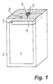
- the insulating container 1 shown in Fig. 1 has a thermally insulating Wall 2 on.
- a cooling module 3 is arranged within the insulated container 1.
- the cooling module 3 has a feed opening 4; which communicates with one Filling opening 5 of the insulating container 1.
- the upper side (hatched area) of Wall 2 of the existing stainless steel insulating container 1 is provided with a trough-shaped depression 6 equipped and the cooling module 3 has a Discharge opening 7 for cooling medium.
- the closure of the insulating container 1 is shown in more detail.
- the filling opening 5 of the insulating container 1 is a trough 6 with a therein arranged annular steel disc 8, said steel disc 8 so in the Insulating material of the thermally insulating wall 2 of the insulating container. 1 is incorporated that no parts over the surface of the upper wall 2 of the Protruding Isolierbeffleiters 1.
- a closure of the filling opening 5 can for Example, a permanent ring magnet 9 are used in the middle of a Insulating material 10 is arranged so that it is in the wall duct 11 of the Filling opening 5 extends and seals there. So can cold losses be avoided as far as possible.
- the wall bushing 11 may as a Tube section be formed and with the outer wall 12 of the cooling module. 3 to lock.
- the steel disc is made of a magnetic or magnetizable Material manufactured, for example a chrome or nickel steel.
- Fig. 3 is a system for supplying cooling medium in the cooling module 3 of a Insulating container 1 by means of a device 13 shown.
- the cooling module 1 has a feed opening 4 for cooling medium, which via an injection tube 14 of the Device 13 is supplied.
- the injection tube 14 is connected to the feed opening 4 for liquid nitrogen or the filling opening 5 connectable.
- a coil 15 of an electromagnet is arranged to the injection tube 14.
- the coil 15 is inside hollow.
- the supply line 16 is arranged.
- the coil 15 can a Detector assigned (not shown here) to the function of the coil too detect.
- the device 13 can also be assigned Have adjusting devices.
- the supply of cooling medium for example, by means of a supply and switchable pump and with the help of a solenoid valve or slide for the cooling medium are regulated. Other control options are as well conceivable and not excluded by the invention.
- the feeder of the Coolant is preferably carried out by actuating an actuator. In conjunction with a corresponding design of the injection tube 14 can such a specially desired amount of cooling medium supplied to the cooling module 3 become.
- the injection can take place only if a secure connection between the injection tube 14 and the cooling module. 3 is made. Therefore, it is envisaged that, for example, the Actuator can only open a shut-off device when through a corresponding sensor, which, for example, the presence of a closed magnetic field detected, the proper function of the Electromagnet is displayed.
- the Actuator can only open a shut-off device when through a corresponding sensor, which, for example, the presence of a closed magnetic field detected, the proper function of the Electromagnet is displayed.
Landscapes
- Engineering & Computer Science (AREA)
- Chemical & Material Sciences (AREA)
- Combustion & Propulsion (AREA)
- Physics & Mathematics (AREA)
- Mechanical Engineering (AREA)
- Thermal Sciences (AREA)
- General Engineering & Computer Science (AREA)
- Packages (AREA)
- Devices That Are Associated With Refrigeration Equipment (AREA)
- Coupling Device And Connection With Printed Circuit (AREA)
Description
Claims (18)
- Isolierbehälter mit einem Kühlmodul und einer Einrichtung (13) zum Zuführen von Kühlmedium, wobei der eine thermische Vakuumisolierung aufweisende und aus Edelstahl bestehende Isolierbehälter (1) im Bereich seiner oberen Wandung (2) eine Füllöffnung (5) aufweist, die in Verbindung steht mit einer Zuführöffnung (4) des Kühlmoduls (3), um dem Kühlmodul (3) ein Kühlmedium zuzuführen und wobei das Kühlmodul (3) zumindest eine Abführöffnung (7) aufweist, woraus Kühlmedium in den Innenraum des Isolierbehälters (1) entweichen kann, um diesen zu kühlen, wobei die Füllöffnung (5) des Isolierbehälters (1) mit der Einrichtung (13) zum Zuführen des Kühlmediums verbunden ist, dadurch gekennzeichnet, daß die Einrichtung (13) im Bereich ihres mit der Füllöffnung (5) verbindbaren Endes magnetische oder elektromagnetische Mittel aufweist, welche mit entsprechenden magnetisierbaren oder magnetischen Mitteln im Bereich der Füllöffnung (5) des Isolierbehälters (1) zusammenwirken, um die Einrichtung (13) zum Zuführen des Kühlmediums an den Isolierbehälter (1) bzw. das Kühlmodul (3) zu koppeln.
- Isolierbehälter nach Anspruch 1, dadurch gekennzeichnet, daß die Einrichtung (13) zum Zuführen des Kühlmediums im Bereich ihres mit der Füllöffnung (5) des Isolierbehälters (1) verbindbaren Endes einen Elektromagneten aufweist und im Bereich der Füllöffnung (5) eine ringförmige Stahlscheibe (8) angeordnet ist.
- Isolierbehälter nach Anspruch 1 oder 2, dadurch gekennzeichnet, daß das Vakuum in der thermischen Vakuumisolierung des Kühlmoduls (3) 0,01 bis 1 mbar beträgt.
- Isolierbehälter nach einem der Ansprüche 1 bis 3, dadurch gekennzeichnet, daß das Kühlmodul (3) tiefkalten, im wesentlichen flüssigen Stickstoff als Kühlmedium enthält.
- Isolierbehälter nach einem der Ansprüche 1 bis 4, dadurch gekennzeichnet, daß die Füllöffnung (5) verschließbar ist mit Hilfe von Verschlussmitteln, welche nicht über die Oberfläche der oberen Wandung (2) des Isolierbehälters (1) hinausragen.
- Isolierbehälter nach Anspruch 5, dadurch gekennzeichnet, daß zumindest ein Teil der Verschlussmittel der Füllöffnung (5) des Isolierbehälters (1) zusammenwirken mit Mitteln der Einrichtung (13) zum Zuführen des Kühlmediums in das Kühlmodul (3), um die Einrichtung (13) zum Zuführen des Kühlmediums an den Isolierbehälter (1) bzw. das Kühlmodul (3) zu koppeln.
- Isolierbehälter nach Anspruch 6, dadurch gekennzeichnet, daß der Einrichtung (13) zum Zuführen des Kühlmediums eine Vorrichtung zur Steuerung der Befüllmenge zugeordnet ist, welche eine Absperreinrichtung und einen in Wirkverbindung mit der Absperreinrichtung stehenden Zeitgeber aufweist, mit dessen Hilfe die Zeitdauer der Zufuhr des Kühlmediums in das Kühlmodul (3) gesteuert wird, um dem Kühlmodul (3) differierende Mengen an Kühlmedium zuzuführen.
- Isolierbehälter nach einem der Ansprüche 1 bis 7, dadurch gekennzeichnet, daß das Kühlmodul (3) lösbar mit dem Isolierbehälter (1) verbunden ist und Einrichtungen aufweist, welche in Wirkverbindung mit entsprechenden Einrichtungen des Isolierbehälters (1) stehen und ein Einschieben und eine Lagerung des Kühlmoduls (3) in dem Isolierbehälter (1) zu ermöglichen.
- Isolierbehälter nach einem der Ansprüche 1 bis 8, dadurch gekennzeichnet, daß im Isolierbehälter (1) mindestens ein Kühlmodul (3) und mindestens eine Kältespeicherplatte benachbart angeordnet sind.
- Isolierbehälter nach einem der Ansprüche 1 bis 9, dadurch gekennzeichnet, daß die Abführöffnung (7) des Kühlmoduls (3) zugleich die Zuführöffnung (4) ist.
- Isolierbehälter nach einem der Ansprüche 1 bis 10, dadurch gekennzeichnet, daß das Aufnahmevolumen des Kühlmoduls (3) an Kühlmedium 500 g bis 15000 g beträgt.
- Verfahren zum Befüllen eines Kühlmoduls (3) in einem Isolierbehälter (1) mit einem Kühlmedium, bei dem das Kühlmedium dem Kühlmodul (3) von oben durch eine Füllöffnung (5) in der oberen Wandung (2) des Isolierbehälters (1) und eine damit in Verbindung stehende Zuführöffnung (4) des Kühlmoduls (3) zugeführt wird, wobei Kühlmedium aus dem Kühlmodul (3) über zumindest eine Abführöffnung (7) in den Innenraum des Isolierbehälters (1) entweichen kann, um diesen zu kühlen, wobei während des Befüllvorgangs eine Einrichtung (13) zum Zuführen des Kuhlmediums an den Isolierbehälter (1) bzw. an das Kühlmodul (3) gekoppelt ist, dadurch gekennzeichnet, daß dies durch magnetische Kraft geschieht .
- Verfahren nach Anspruch 12, dadurch gekennzeichnet, dass die magnetische Kraft mit Hilfe eines Elektromagneten im Bereich des mit der Füllöffnung (5) verbindbaren Endes der Einrichtung (13) zum Zuführen des Kühlmediums und mit Hilfe einer im Bereich der Füllöffnung (5) angeordneten Stahlscheibe (8) ausgeübt wird.
- Verfahren nach Anspruch 12 oder 13, dadurch gekennzeichnet, daß eine Menge von 800 bis 1200 g an Kühlmedium innerhalb einer Stunde verdampft.
- Verfahren nach einem der Ansprüche 12 bis 14, dadurch gekennzeichnet, daß die Zeitdauer der Zufuhr des Kühlmediums in das Kühlmodul (3) durch eine der Befülleinrichtung zugeordnete Steuereinrichtung gesteuert wird, um dem Kühlmodul (3) differierende Mengen an Kühlmedium zuzuführen und so eine zeitlich gewünschte Kältekonservierung der Stoffe innerhalb des Isolierbehälters (1) einzustellen.
- Verfahren nach einem der Ansprüche 12 bis 15, dadurch gekennzeichnet, daß tiefkalter verflüssigter Stickstoff als Kühlmedium verwendet wird.
- Verwendung eines Isolierbehälters nach einem der Ansprüche 1 bis 11 oder eines Verfahrens nach einem der Ansprüche 12 bis 16 zur zeitlich begrenzten Kältekonservierung von temperaturempfindlichen Stoffen.
- Verwendung nach Anspruch 17 zur Kühlung von Lebensmitteln.
Applications Claiming Priority (3)
| Application Number | Priority Date | Filing Date | Title |
|---|---|---|---|
| DE19858061 | 1998-12-16 | ||
| DE19858061A DE19858061A1 (de) | 1998-12-16 | 1998-12-16 | Isolierbehälter mit befüllbarem Kühlmodul |
| PCT/EP1999/009727 WO2000036348A1 (de) | 1998-12-16 | 1999-12-10 | Isolierbehälter mit befüllbarem kühlmodul |
Publications (2)
| Publication Number | Publication Date |
|---|---|
| EP1141638A1 EP1141638A1 (de) | 2001-10-10 |
| EP1141638B1 true EP1141638B1 (de) | 2003-12-03 |
Family
ID=7891297
Family Applications (1)
| Application Number | Title | Priority Date | Filing Date |
|---|---|---|---|
| EP99958183A Expired - Lifetime EP1141638B1 (de) | 1998-12-16 | 1999-12-10 | Isolierbehälter mit einem befüllbarem kühlmodul und einer einrichtung zum zuführen von kühlmedium |
Country Status (8)
| Country | Link |
|---|---|
| EP (1) | EP1141638B1 (de) |
| AT (1) | ATE255717T1 (de) |
| AU (1) | AU1560500A (de) |
| CZ (1) | CZ303202B6 (de) |
| DE (2) | DE19858061A1 (de) |
| HU (1) | HUP0104706A3 (de) |
| PL (1) | PL195850B1 (de) |
| WO (1) | WO2000036348A1 (de) |
Families Citing this family (5)
| Publication number | Priority date | Publication date | Assignee | Title |
|---|---|---|---|---|
| DE10129809B4 (de) * | 2001-06-23 | 2005-03-10 | Annemarie Appelmann | Passiver, transportabler Gärverzögerer |
| DE10259553A1 (de) * | 2002-12-19 | 2004-07-15 | Messer Griesheim Gmbh | Kältegerät |
| DE10259551A1 (de) * | 2002-12-19 | 2004-07-15 | Messer Griesheim Gmbh | Isolierbehälter |
| EP1431686B1 (de) | 2002-12-19 | 2010-05-19 | Air Liquide Deutschland GmbH | Isolierbehälter |
| WO2012176075A2 (en) * | 2011-06-22 | 2012-12-27 | Gavrylov Roland Volodymyrovych | Methods for transportation of thermally unstable products |
Family Cites Families (9)
| Publication number | Priority date | Publication date | Assignee | Title |
|---|---|---|---|---|
| DE6940423U (de) * | 1969-10-05 | 1970-03-19 | Hans-Juergen Moench | Steckbrettartige merktafel zur kennzeichnung sehenswerter fernsehsendungen im verlauf eines wochenprogramms. |
| FR2227746A5 (en) * | 1973-04-24 | 1974-11-22 | Pasquier Lucien | Self-contained refrigerated food container - comprises two compartments, the lower holding a liquified gas bottle |
| DE2731858A1 (de) * | 1977-07-14 | 1979-02-01 | Martin A Dipl Ing Frank | Verfahren zur kuehlhaltung von guetern in kuehlcontainern und kuehlcontainer |
| GB2163538A (en) * | 1984-07-03 | 1986-02-26 | Peter Frank Goodall | A small transportable container for chilled or frozen products or for products requiring controlled atmospheres or environments |
| AU6648886A (en) * | 1985-12-27 | 1987-07-02 | Morita, T. | Magnetic fastener |
| US4794761A (en) * | 1987-08-11 | 1989-01-03 | Benny Fredrixon | Top structure for cold or freeze transport container |
| DE4013669A1 (de) * | 1990-04-27 | 1991-10-31 | Man Nutzfahrzeuge Ag | Verfahren und vorrichtung zum umweltfreundlichen ablassen von fluiden |
| JP2867116B2 (ja) * | 1994-12-12 | 1999-03-08 | 株式会社コルポ | 低温保存品収納用コンテナ及びコンテナ冷却装置 |
| GB9613421D0 (en) * | 1996-06-26 | 1996-08-28 | Boc Group Plc | Refrigerated Container |
-
1998
- 1998-12-16 DE DE19858061A patent/DE19858061A1/de not_active Ceased
-
1999
- 1999-12-10 EP EP99958183A patent/EP1141638B1/de not_active Expired - Lifetime
- 1999-12-10 AT AT99958183T patent/ATE255717T1/de active
- 1999-12-10 WO PCT/EP1999/009727 patent/WO2000036348A1/de not_active Ceased
- 1999-12-10 HU HU0104706A patent/HUP0104706A3/hu unknown
- 1999-12-10 AU AU15605/00A patent/AU1560500A/en not_active Abandoned
- 1999-12-10 PL PL99349740A patent/PL195850B1/pl not_active IP Right Cessation
- 1999-12-10 DE DE59907966T patent/DE59907966D1/de not_active Expired - Lifetime
- 1999-12-10 CZ CZ20012092A patent/CZ303202B6/cs not_active IP Right Cessation
Also Published As
| Publication number | Publication date |
|---|---|
| HUP0104706A3 (en) | 2002-05-28 |
| CZ20012092A3 (cs) | 2002-07-17 |
| DE19858061A1 (de) | 2000-07-06 |
| HUP0104706A2 (hu) | 2002-03-28 |
| PL195850B1 (pl) | 2007-10-31 |
| CZ303202B6 (cs) | 2012-05-23 |
| DE59907966D1 (de) | 2004-01-15 |
| ATE255717T1 (de) | 2003-12-15 |
| EP1141638A1 (de) | 2001-10-10 |
| WO2000036348A1 (de) | 2000-06-22 |
| AU1560500A (en) | 2000-07-03 |
Similar Documents
| Publication | Publication Date | Title |
|---|---|---|
| EP1088191B1 (de) | Befüll- und entnahmemodul für ein kühlmodul und verfahren zum befüllen eines kühlmoduls | |
| DE69526039T2 (de) | Verfahren und Vorrichtung zum Fördern und Lagern von gekühlten Waren | |
| DE69404231T2 (de) | Verfahren zur Konservierung von Waren bei niedrigen Temperaturen in einem isolierten Gehäuse, Vorrichtung zur Durchführung des Verfahrens, isoliertes Gehäuse und Behälter für solch ein Gehäuse | |
| EP2336684B1 (de) | Befüllvorrichtung zum Befüllen eines einem Kühlbehälter zugeordneten Kältemittel-Aufnahmefachs mit einem kryogenen Kältemittel | |
| DE2748796A1 (de) | Verfahren und vorrichtung zum kuehlen von materialien unter verwendung von gespeicherter, kaelteerzeugender kuehlung | |
| DE112011100483T5 (de) | Flüssigluft-Kühlsystem für Speicherbehälter | |
| EP0077960B1 (de) | Kühlgutbehälter zum Kühlen eines Kühlgutes in einem Behälter | |
| EP1110043B1 (de) | Vorrichtung und verfahren zum kühlen eines behälters | |
| EP0429499B1 (de) | Kühlverfahren und kühlbehälter | |
| DE19735584C2 (de) | Doppelwandige Kühlzelle | |
| DE2407014A1 (de) | Kuehlverfahren und kuehlbehaelter | |
| EP1141638A1 (de) | Isolierbehälter mit befüllbarem kühlmodul | |
| DE19518344A1 (de) | Schnellgefriervorrichtung | |
| DE102016211437B4 (de) | Kältegerät mit Schnellgefrierfunktion | |
| EP3667209B1 (de) | Haushaltskältegerät | |
| DE68927738T2 (de) | Spender zur ausgabe gefrorener süssigkeiten in weichem zustand | |
| DE60107173T2 (de) | Verfahren und Vorrichtung zur Verpackung von Kohlendioxidschnee mittels eines Kunststoffilms | |
| DE60022125T2 (de) | Tiefstkühlen von Waren | |
| DE3833753A1 (de) | Verfahren und vorrichtungen zum tiefkuehlen von kohlendioxidgasfoermig und stickstoff-gasfoermig aus druckbehaeltern, beziehungsweise luft aus druckflaschen oder -erzeugern und deren tiefkalte anwendung | |
| DE3003987C2 (de) | Wärmeisolierter Kleincontainer für den mehrstündigen Transport gekühlter Lebensmittel | |
| DE19629034A1 (de) | Tragtasche | |
| EP1019662B1 (de) | Einrichtung für temperaturempfindliche waren | |
| EP3058058B1 (de) | Verfahren und kühlsystem zum übertragen von wärme aus einem medium auf einen wärmeträger in einem verfahren zur lebensmittelherstellung, vorzugsweise bei der getränkeherstellung, insbesondere bei der bierherstellung; und entsprechende verwendungen | |
| WO2001092797A1 (de) | Verfahren zum frischhalten verderblicher güter innerhalb eines vorratsschrankes sowie vorratsschrank zum durchführen dieses verfahrens | |
| DE3702807A1 (de) | Vorrichtung zum kuehlen von lebensmitteln |
Legal Events
| Date | Code | Title | Description |
|---|---|---|---|
| PUAI | Public reference made under article 153(3) epc to a published international application that has entered the european phase |
Free format text: ORIGINAL CODE: 0009012 |
|
| 17P | Request for examination filed |
Effective date: 20010716 |
|
| AK | Designated contracting states |
Kind code of ref document: A1 Designated state(s): AT BE CH CY DE DK ES FI FR GB GR IE IT LI LU MC NL PT SE |
|
| AX | Request for extension of the european patent |
Free format text: AL;LT;LV;MK;RO;SI |
|
| 17Q | First examination report despatched |
Effective date: 20020628 |
|
| RAP1 | Party data changed (applicant data changed or rights of an application transferred) |
Owner name: MESSER GRIESHEIM GMBH |
|
| GRAH | Despatch of communication of intention to grant a patent |
Free format text: ORIGINAL CODE: EPIDOS IGRA |
|
| RTI1 | Title (correction) |
Free format text: INSULATED CONTAINER WITH FILLABLE COOLING MODULE AND DEVICE FOR SUPPLY OF COOLING MEDIUM |
|
| GRAS | Grant fee paid |
Free format text: ORIGINAL CODE: EPIDOSNIGR3 |
|
| GRAA | (expected) grant |
Free format text: ORIGINAL CODE: 0009210 |
|
| AK | Designated contracting states |
Kind code of ref document: B1 Designated state(s): AT BE CH CY DE DK ES FI FR GB GR IE IT LI LU MC NL PT SE |
|
| PG25 | Lapsed in a contracting state [announced via postgrant information from national office to epo] |
Ref country code: IE Free format text: LAPSE BECAUSE OF FAILURE TO SUBMIT A TRANSLATION OF THE DESCRIPTION OR TO PAY THE FEE WITHIN THE PRESCRIBED TIME-LIMIT Effective date: 20031203 Ref country code: GB Free format text: LAPSE BECAUSE OF FAILURE TO SUBMIT A TRANSLATION OF THE DESCRIPTION OR TO PAY THE FEE WITHIN THE PRESCRIBED TIME-LIMIT Effective date: 20031203 Ref country code: FI Free format text: LAPSE BECAUSE OF FAILURE TO SUBMIT A TRANSLATION OF THE DESCRIPTION OR TO PAY THE FEE WITHIN THE PRESCRIBED TIME-LIMIT Effective date: 20031203 |
|
| REG | Reference to a national code |
Ref country code: GB Ref legal event code: FG4D Free format text: NOT ENGLISH |
|
| PG25 | Lapsed in a contracting state [announced via postgrant information from national office to epo] |
Ref country code: LU Free format text: LAPSE BECAUSE OF NON-PAYMENT OF DUE FEES Effective date: 20031210 Ref country code: CY Free format text: LAPSE BECAUSE OF FAILURE TO SUBMIT A TRANSLATION OF THE DESCRIPTION OR TO PAY THE FEE WITHIN THE PRESCRIBED TIME-LIMIT Effective date: 20031210 |
|
| REG | Reference to a national code |
Ref country code: CH Ref legal event code: EP |
|
| PG25 | Lapsed in a contracting state [announced via postgrant information from national office to epo] |
Ref country code: MC Free format text: LAPSE BECAUSE OF NON-PAYMENT OF DUE FEES Effective date: 20031231 |
|
| REG | Reference to a national code |
Ref country code: IE Ref legal event code: FG4D Free format text: GERMAN |
|
| REF | Corresponds to: |
Ref document number: 59907966 Country of ref document: DE Date of ref document: 20040115 Kind code of ref document: P |
|
| PG25 | Lapsed in a contracting state [announced via postgrant information from national office to epo] |
Ref country code: SE Free format text: LAPSE BECAUSE OF FAILURE TO SUBMIT A TRANSLATION OF THE DESCRIPTION OR TO PAY THE FEE WITHIN THE PRESCRIBED TIME-LIMIT Effective date: 20040303 Ref country code: GR Free format text: LAPSE BECAUSE OF FAILURE TO SUBMIT A TRANSLATION OF THE DESCRIPTION OR TO PAY THE FEE WITHIN THE PRESCRIBED TIME-LIMIT Effective date: 20040303 Ref country code: DK Free format text: LAPSE BECAUSE OF FAILURE TO SUBMIT A TRANSLATION OF THE DESCRIPTION OR TO PAY THE FEE WITHIN THE PRESCRIBED TIME-LIMIT Effective date: 20040303 |
|
| PG25 | Lapsed in a contracting state [announced via postgrant information from national office to epo] |
Ref country code: ES Free format text: LAPSE BECAUSE OF FAILURE TO SUBMIT A TRANSLATION OF THE DESCRIPTION OR TO PAY THE FEE WITHIN THE PRESCRIBED TIME-LIMIT Effective date: 20040314 |
|
| GBV | Gb: ep patent (uk) treated as always having been void in accordance with gb section 77(7)/1977 [no translation filed] |
Effective date: 20031203 |
|
| REG | Reference to a national code |
Ref country code: IE Ref legal event code: FD4D |
|
| RAP2 | Party data changed (patent owner data changed or rights of a patent transferred) |
Owner name: MESSER GROUP GMBH |
|
| ET | Fr: translation filed | ||
| PLBE | No opposition filed within time limit |
Free format text: ORIGINAL CODE: 0009261 |
|
| STAA | Information on the status of an ep patent application or granted ep patent |
Free format text: STATUS: NO OPPOSITION FILED WITHIN TIME LIMIT |
|
| RAP2 | Party data changed (patent owner data changed or rights of a patent transferred) |
Owner name: MESSER GROUP GMBH Owner name: MESSER GRIESHEIM GMBH |
|
| RAP2 | Party data changed (patent owner data changed or rights of a patent transferred) |
Owner name: MESSER GROUP GMBH Owner name: MESSER GRIESHEIM GMBH |
|
| NLT2 | Nl: modifications (of names), taken from the european patent patent bulletin |
Owner name: MESSER GROUP GMBH |
|
| 26N | No opposition filed |
Effective date: 20040906 |
|
| NLT2 | Nl: modifications (of names), taken from the european patent patent bulletin |
Owner name: MESSER GROUP GMBH |
|
| NLT2 | Nl: modifications (of names), taken from the european patent patent bulletin |
Owner name: MESSER GROUP GMBH |
|
| PG25 | Lapsed in a contracting state [announced via postgrant information from national office to epo] |
Ref country code: PT Free format text: LAPSE BECAUSE OF NON-PAYMENT OF DUE FEES Effective date: 20040503 |
|
| PGFP | Annual fee paid to national office [announced via postgrant information from national office to epo] |
Ref country code: CH Payment date: 20121213 Year of fee payment: 14 |
|
| PGFP | Annual fee paid to national office [announced via postgrant information from national office to epo] |
Ref country code: IT Payment date: 20121213 Year of fee payment: 14 |
|
| PGFP | Annual fee paid to national office [announced via postgrant information from national office to epo] |
Ref country code: AT Payment date: 20121127 Year of fee payment: 14 Ref country code: NL Payment date: 20121208 Year of fee payment: 14 Ref country code: FR Payment date: 20130107 Year of fee payment: 14 |
|
| PGFP | Annual fee paid to national office [announced via postgrant information from national office to epo] |
Ref country code: BE Payment date: 20121217 Year of fee payment: 14 |
|
| BERE | Be: lapsed |
Owner name: *MESSER GRIESHEIM G.M.B.H. Effective date: 20131231 |
|
| REG | Reference to a national code |
Ref country code: NL Ref legal event code: V1 Effective date: 20140701 |
|
| REG | Reference to a national code |
Ref country code: CH Ref legal event code: PL |
|
| REG | Reference to a national code |
Ref country code: AT Ref legal event code: MM01 Ref document number: 255717 Country of ref document: AT Kind code of ref document: T Effective date: 20131210 |
|
| REG | Reference to a national code |
Ref country code: FR Ref legal event code: ST Effective date: 20140829 |
|
| PG25 | Lapsed in a contracting state [announced via postgrant information from national office to epo] |
Ref country code: LI Free format text: LAPSE BECAUSE OF NON-PAYMENT OF DUE FEES Effective date: 20131231 Ref country code: NL Free format text: LAPSE BECAUSE OF NON-PAYMENT OF DUE FEES Effective date: 20140701 Ref country code: CH Free format text: LAPSE BECAUSE OF NON-PAYMENT OF DUE FEES Effective date: 20131231 Ref country code: BE Free format text: LAPSE BECAUSE OF NON-PAYMENT OF DUE FEES Effective date: 20131231 |
|
| PG25 | Lapsed in a contracting state [announced via postgrant information from national office to epo] |
Ref country code: FR Free format text: LAPSE BECAUSE OF NON-PAYMENT OF DUE FEES Effective date: 20131231 Ref country code: AT Free format text: LAPSE BECAUSE OF NON-PAYMENT OF DUE FEES Effective date: 20131210 |
|
| PG25 | Lapsed in a contracting state [announced via postgrant information from national office to epo] |
Ref country code: IT Free format text: LAPSE BECAUSE OF NON-PAYMENT OF DUE FEES Effective date: 20131231 |
|
| PG25 | Lapsed in a contracting state [announced via postgrant information from national office to epo] |
Ref country code: IT Free format text: LAPSE BECAUSE OF NON-PAYMENT OF DUE FEES Effective date: 20131210 |
|
| PGFP | Annual fee paid to national office [announced via postgrant information from national office to epo] |
Ref country code: DE Payment date: 20181210 Year of fee payment: 20 |
|
| REG | Reference to a national code |
Ref country code: DE Ref legal event code: R071 Ref document number: 59907966 Country of ref document: DE |