EP1141583B1 - Antrieb für einen rotierenden gegenstand, wie eine walze, welle, platte oder dergleichen - Google Patents
Antrieb für einen rotierenden gegenstand, wie eine walze, welle, platte oder dergleichen Download PDFInfo
- Publication number
- EP1141583B1 EP1141583B1 EP99959636A EP99959636A EP1141583B1 EP 1141583 B1 EP1141583 B1 EP 1141583B1 EP 99959636 A EP99959636 A EP 99959636A EP 99959636 A EP99959636 A EP 99959636A EP 1141583 B1 EP1141583 B1 EP 1141583B1
- Authority
- EP
- European Patent Office
- Prior art keywords
- lever
- drive
- tooth
- drive mechanism
- gear wheel
- Prior art date
- Legal status (The legal status is an assumption and is not a legal conclusion. Google has not performed a legal analysis and makes no representation as to the accuracy of the status listed.)
- Expired - Lifetime
Links
- 230000033001 locomotion Effects 0.000 claims abstract description 25
- 230000008878 coupling Effects 0.000 claims description 6
- 238000010168 coupling process Methods 0.000 claims description 6
- 238000005859 coupling reaction Methods 0.000 claims description 6
- 239000003205 fragrance Substances 0.000 claims description 4
- 238000005096 rolling process Methods 0.000 abstract description 2
- 239000007788 liquid Substances 0.000 description 8
- 238000004519 manufacturing process Methods 0.000 description 6
- 238000004140 cleaning Methods 0.000 description 2
- 230000006835 compression Effects 0.000 description 2
- 238000007906 compression Methods 0.000 description 2
- 238000003860 storage Methods 0.000 description 2
- 241000237858 Gastropoda Species 0.000 description 1
- 239000000654 additive Substances 0.000 description 1
- 230000000996 additive effect Effects 0.000 description 1
- 230000005540 biological transmission Effects 0.000 description 1
- 230000015572 biosynthetic process Effects 0.000 description 1
- 238000012824 chemical production Methods 0.000 description 1
- 238000005352 clarification Methods 0.000 description 1
- 238000011109 contamination Methods 0.000 description 1
- 238000011161 development Methods 0.000 description 1
- 230000018109 developmental process Effects 0.000 description 1
- 230000003670 easy-to-clean Effects 0.000 description 1
- 230000001771 impaired effect Effects 0.000 description 1
- 238000013519 translation Methods 0.000 description 1
- 230000014616 translation Effects 0.000 description 1
- XLYOFNOQVPJJNP-UHFFFAOYSA-N water Substances O XLYOFNOQVPJJNP-UHFFFAOYSA-N 0.000 description 1
Images


Classifications
-
- F—MECHANICAL ENGINEERING; LIGHTING; HEATING; WEAPONS; BLASTING
- F16—ENGINEERING ELEMENTS AND UNITS; GENERAL MEASURES FOR PRODUCING AND MAINTAINING EFFECTIVE FUNCTIONING OF MACHINES OR INSTALLATIONS; THERMAL INSULATION IN GENERAL
- F16H—GEARING
- F16H31/00—Other gearings with freewheeling members or other intermittently driving members
- F16H31/003—Step-by-step mechanisms for rotary motion
- F16H31/004—Step-by-step mechanisms for rotary motion with pawls driven by a rotary cam
-
- A—HUMAN NECESSITIES
- A61—MEDICAL OR VETERINARY SCIENCE; HYGIENE
- A61L—METHODS OR APPARATUS FOR STERILISING MATERIALS OR OBJECTS IN GENERAL; DISINFECTION, STERILISATION OR DEODORISATION OF AIR; CHEMICAL ASPECTS OF BANDAGES, DRESSINGS, ABSORBENT PADS OR SURGICAL ARTICLES; MATERIALS FOR BANDAGES, DRESSINGS, ABSORBENT PADS OR SURGICAL ARTICLES
- A61L9/00—Disinfection, sterilisation or deodorisation of air
- A61L9/015—Disinfection, sterilisation or deodorisation of air using gaseous or vaporous substances, e.g. ozone
- A61L9/04—Disinfection, sterilisation or deodorisation of air using gaseous or vaporous substances, e.g. ozone using substances evaporated in the air without heating
- A61L9/12—Apparatus, e.g. holders, therefor
-
- F—MECHANICAL ENGINEERING; LIGHTING; HEATING; WEAPONS; BLASTING
- F24—HEATING; RANGES; VENTILATING
- F24F—AIR-CONDITIONING; AIR-HUMIDIFICATION; VENTILATION; USE OF AIR CURRENTS FOR SCREENING
- F24F8/00—Treatment, e.g. purification, of air supplied to human living or working spaces otherwise than by heating, cooling, humidifying or drying
- F24F8/50—Treatment, e.g. purification, of air supplied to human living or working spaces otherwise than by heating, cooling, humidifying or drying by odorisation
-
- Y—GENERAL TAGGING OF NEW TECHNOLOGICAL DEVELOPMENTS; GENERAL TAGGING OF CROSS-SECTIONAL TECHNOLOGIES SPANNING OVER SEVERAL SECTIONS OF THE IPC; TECHNICAL SUBJECTS COVERED BY FORMER USPC CROSS-REFERENCE ART COLLECTIONS [XRACs] AND DIGESTS
- Y10—TECHNICAL SUBJECTS COVERED BY FORMER USPC
- Y10T—TECHNICAL SUBJECTS COVERED BY FORMER US CLASSIFICATION
- Y10T74/00—Machine element or mechanism
- Y10T74/19—Gearing
- Y10T74/19642—Directly cooperating gears
- Y10T74/19698—Spiral
- Y10T74/19828—Worm
Definitions
- the invention relates to a drive for a rotating Subject according to the preamble of claim 1.
- the centerpiece of this drive is at least one swiveling mounted lever that cooperates with a gear that is non-rotatably connected to the rotating object.
- a device for storing and guiding the Lever for an engaging and entraining in the gear Forward movement of the lever is present.
- This drive has the advantage that it is essentially is insensitive to contamination caused by a Liquid occur in which rollers, shafts or the like in an air humidifying and cleaning device, a fragrance evaporator or the like rotates. Because itself if the gear is rotated in the Liquid is wetted by this is the only one Point of contact with the other gear components in the Part of the lever that engages the gear. this part the lever is usually easy to clean.
- a disadvantage of this mechanism is that in particular by the occurrence of manufacturing tolerances Drive parts a smooth, quiet running of the rotating object is sometimes impaired because especially the engaged lever with the gear can get caught.
- the invention is based on the object of a drive create, which has an improved synchronization and in particular less sensitive to manufacturing tolerances is.
- the invention is based on a drive for a rotating one Object for a roller, shaft, plate or the like, especially for a fragrance evaporator, a humidifier or an air purifier or the like made of has the following characteristics:
- a movably mounted lever, a gear that rotates is connected to the rotating object and a Lever gear for a meshing and entraining movement of the lever to rotate the gear, the lever for engaging the teeth of the gear a Has tip.
- the main idea of the invention is now in that the tip is in the form of a tooth, the shape of this tooth and that of the teeth of the gear and the lever gear are matched to one another in such a way that the tooth flanks of the tooth on at least one lever and of the currently engaged tooth on the gear at the Transfer driving movement on each other.
- the shape of the tooth on the lever and that of the teeth of the gear and the lever gear are coordinated so that the tooth flanks of the Tooth on at least one lever and each in engagement stationary tooth on the gearwheel during the entraining movement have a point of contact in which the flanks without Roll radial sliding on each other (pitch point).
- the shape of the tooth on the lever and that of Teeth on the gear according to the rules of gearing as Involute, cycloid, circular or as Triebstock toothing, in which the tooth on the lever e.g. the Has the shape of a pin, trained.
- gearing as Involute, cycloid, circular or as Triebstock toothing, in which the tooth on the lever e.g. the Has the shape of a pin, trained.
- the lever mechanism for pushing the lever Guide surfaces for the lever.
- This allows the lever to be guided for example a forward movement, a backward movement as well as perform a swivel movement.
- the lever mechanism one Eccentric drive for the lever includes.
- this be a drive shaft for the Has lever, which is arranged eccentrically on a gear is.
- the gear can be driven continuously preferably with the help of a snail. This means that extreme translations possible, which is particularly the case with Use in a fragrance evaporator according to the invention or Air washer where only one motor drives the Fan and drive one or two stacks of plates is used is necessary.
- Worm gear a so-called self-locking gear represents, whereby the at least one lever against one unwanted movement is blocked.
- the drive shaft mounted directly eccentrically on a gearwheel, which from a worm is driven.
- the worm is preferably connected via an elastic coupling connected to the drive shaft of a motor. hereby the drive shaft does not need to be completely in line to stand with the worm shaft. Larger tolerances in the Manufacture of a drive according to the invention are here possible, which among other things a cost saving brings.
- two, three or more levers are provided, which alternate engage the gear.
- the lever by a Worm gear locked against unwanted movement are that the rotating object by at least an engaged lever against any unwanted further movement, for example against turning back is secured. The rotation of the rotating object is thus always mechanically fixed by the lever drive controlled.
- the at least a lever between the guide surfaces of the lever gear is mounted elastically. This will pull the lever in Lever gear biased and also has Manufacturing tolerances no play. Too big a game could lead to the worst case that the tooth of a engaging lever collides with a tooth of the gear or your teeth get caught.
- the elastic Storage of the lever between the guide surfaces at least part of the outer contour of the guide surfaces Lever is resilient.
- the outer contour as narrow frame is formed.
- this has Contour area resilient properties.
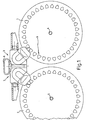
- Fig. 1 are two parallel stacked plates 1, 2 an air humidification device arranged thereon Drives 3 according to the invention in a schematic Side view shown.
- the plate stack 1, 2 exist z. B. from lamellar arranged one behind the other circular discs.
- the plate stack 1, 2 are in Air washers usually stored on a tub (not shown), in which there is usually water, if necessary with an additive in which the plate stack immerse when rotating around axes 4, 5.
- a housing cover on the z. B. a fan is arranged with a drive motor, which has an elastic Coupling 6 with two drives 3 in accordance with the invention Connection is established.
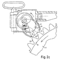
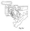
- the lever gear 7 is an arrangement with two drive levers 9, 10.
- the Drive levers 9, 10 each have a tooth shape configured tip 11, 12 and a receiving opening 13, 14 (See also Fig. 3a and b) for two drive pins 15, 16.
- the drive pins 15, 16 are on the two End faces of a worm wheel 17 eccentrically by 180 ° staggered and thus form an eccentric Bearing seat for it on the receiving openings 13, 14th attached drive lever 9, 10.
- the worm wheel 17 has an axis of rotation 18 in the housing of the lever mechanism 7 is mounted and is in engagement with a worm 19.
- the worm 19 is connected via the elastic coupling 6 with e.g. connected to a drive motor, not shown.
- a Rotation of the screw 19 and a rotation of the Worm wheel 17 e.g. in the direction of the arrow eccentric bearing seat 13, 14, 15, 16 of the drive lever 9, 10 this back and forth in the housing of the lever gear 7 moved or pivoted.
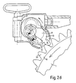
- the front drive lever 10 in shown by solid lines in engagement with the Teeth of the ring gear 8, while the second behind it arranged drive lever 9 (in dashed lines shown) completely from the toothing of the ring gear 8 withdrawn.
- the desired movement of the tooth-shaped Tips 11, 12 of the drive lever 9, 10 results in Essentially from the geometric distances of the eccentric arranged drive pin 15, 16 and the shape and Distance of the guide surfaces 20, 21.
- the trajectory of the tooth-shaped tips 11, 12 is the coupling curve of the thus realized push crank drive.
- teeth 22 of the ring gear 8 and the tooth-shaped tip 11, 12 is designed so that the interlocking teeth exemplify one Realize cycloid gearing.
- the movement the drive lever 9, 10 through the eccentric bearing as well the guide surfaces on the housing of the lever gearbox so coordinated that the tooth flanks roll on each other.
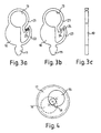
- the drive lever 10 is an example in FIGS. 3a to c shown again in detail.
- the outer contour of the Drive lever 10 is on a large area Side formed as a narrow frame 23. Before the Receiving opening 13, the frame 23 is interrupted and points Locating pin 24 for a compression spring 25 (only in Fig. 3a shown). This way the front area of the Drive lever 10 on this side resilient. This allows the drive lever 10 or the same Drive lever 9 with bias in the housing of Use lever gear 7. This prevents occurring manufacturing tolerances the lever 9, 10 a game that, if necessary, leads to the tip 11, 12 of a drive lever 9, 10 with a tooth of the ring gear 8 collided or hooked. Because of the asymmetrical Frame formation is achieved that the lever on a Can support the guide surface without giving in. This is preferably the side that has the essential forces for the Continues movement of the gear.
- the tips 11, 12 the drive lever 9, 10 directed downwards downward, so that liquid by immersing the ring gear 8 conveyed to the lever tips 11, 12 in a liquid bath will run back down to the ring gear 8.
- the device is disassembled for cleaning work for the layperson in a simple way, since with the acceptance of the Cover (not shown) just the stack of plates 1, 2 are in the tub (not shown).
- the drive shown for a plate stack 1, 2 can itself outside of an invention Use a humidifier.
- the system shown can be easily applied to any rotating object apply, in which a drive system according to the invention Offers advantages. This can be especially true with chemical Production facilities, where rolls, Drums, heat exchangers or the like within one Have to turn the liquid bath and thus that too Problem is that the drive is not or only with point the possibly aggressive liquid in contact may come.
- the drive principle according to the invention can also be used advantageously when a very large Ratio between the drive shaft and the rotating Object to be realized.
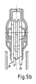
- 5a and b is a variant of an inventive Drive shown, instead of two drive levers three drive levers 26, 27, 28 are used. In correspondingly, drive pins are on one Worm gear 29 not eccentric by 180 ° but by 120 ° added.
- Fig. 5b Clarification of the position of the drive lever 26, 27, 28 in Longitudinal section is shown, an even improved Achieve synchronism.
Landscapes
- Engineering & Computer Science (AREA)
- General Engineering & Computer Science (AREA)
- Health & Medical Sciences (AREA)
- Mechanical Engineering (AREA)
- Public Health (AREA)
- Life Sciences & Earth Sciences (AREA)
- Animal Behavior & Ethology (AREA)
- General Health & Medical Sciences (AREA)
- Epidemiology (AREA)
- Veterinary Medicine (AREA)
- Combustion & Propulsion (AREA)
- Chemical & Material Sciences (AREA)
- Transmission Devices (AREA)
- Rollers For Roller Conveyors For Transfer (AREA)
- Rolls And Other Rotary Bodies (AREA)
- General Details Of Gearings (AREA)
- Preliminary Treatment Of Fibers (AREA)
- Disinfection, Sterilisation Or Deodorisation Of Air (AREA)
- Gear Transmission (AREA)
Applications Claiming Priority (3)
| Application Number | Priority Date | Filing Date | Title |
|---|---|---|---|
| US222726 | 1998-12-29 | ||
| US09/222,726 US6318203B1 (en) | 1998-12-29 | 1998-12-29 | Drive for rotating object such as a roller, shaft, plate or the like |
| PCT/IB1999/002063 WO2000039485A1 (de) | 1998-12-29 | 1999-12-29 | Antrieb für einen rotierenden gegenstand, wie eine walze, welle, platte oder dergleichen |
Publications (2)
| Publication Number | Publication Date |
|---|---|
| EP1141583A1 EP1141583A1 (de) | 2001-10-10 |
| EP1141583B1 true EP1141583B1 (de) | 2003-07-30 |
Family
ID=22833425
Family Applications (1)
| Application Number | Title | Priority Date | Filing Date |
|---|---|---|---|
| EP99959636A Expired - Lifetime EP1141583B1 (de) | 1998-12-29 | 1999-12-29 | Antrieb für einen rotierenden gegenstand, wie eine walze, welle, platte oder dergleichen |
Country Status (10)
| Country | Link |
|---|---|
| US (1) | US6318203B1 (enExample) |
| EP (1) | EP1141583B1 (enExample) |
| JP (1) | JP4540852B2 (enExample) |
| KR (1) | KR100646717B1 (enExample) |
| CN (1) | CN1099534C (enExample) |
| AT (1) | ATE246321T1 (enExample) |
| CA (1) | CA2347672C (enExample) |
| DE (2) | DE19958078A1 (enExample) |
| NO (1) | NO320077B1 (enExample) |
| WO (1) | WO2000039485A1 (enExample) |
Cited By (1)
| Publication number | Priority date | Publication date | Assignee | Title |
|---|---|---|---|---|
| EP1647322A2 (de) | 2004-10-15 | 2006-04-19 | Edgar Emele Kunststofftechnik Präzisionsformen GmbH & Co. KG | Luftwäschegerät zur Luftreinigung und/oder Luftbefeuchtung |
Families Citing this family (6)
| Publication number | Priority date | Publication date | Assignee | Title |
|---|---|---|---|---|
| US10194516B2 (en) | 2006-09-13 | 2019-01-29 | Hypertherm, Inc. | High access consumables for a plasma arc cutting system |
| US10098217B2 (en) | 2012-07-19 | 2018-10-09 | Hypertherm, Inc. | Composite consumables for a plasma arc torch |
| US9662747B2 (en) | 2006-09-13 | 2017-05-30 | Hypertherm, Inc. | Composite consumables for a plasma arc torch |
| US9560732B2 (en) | 2006-09-13 | 2017-01-31 | Hypertherm, Inc. | High access consumables for a plasma arc cutting system |
| KR20160115305A (ko) | 2015-03-26 | 2016-10-06 | 진정현 | 차량용 오일 수거장치 |
| KR20200095099A (ko) | 2019-01-31 | 2020-08-10 | 길은미 | 차량용 폐오일 수거장치 |
Family Cites Families (11)
| Publication number | Priority date | Publication date | Assignee | Title |
|---|---|---|---|---|
| FR989820A (fr) * | 1949-04-30 | 1951-09-13 | Mécanisme réducteur de vitesses | |
| DE2011245A1 (de) * | 1970-03-10 | 1971-09-23 | Zahnradfabrik Friedrichshafen Ag, 7990 Friedrichshafen | Evolventen-Schrägverzahnung für Stirnräder mit Außen- und Innenverzahnung, und Werkzeug zur Fertigbearbeitung |
| US3738185A (en) * | 1971-04-26 | 1973-06-12 | Scott & Fetzer Co | Sequential timer |
| US3834680A (en) * | 1972-06-12 | 1974-09-10 | W Walker | Air conditioning apparatus for a vehicle cab |
| US4261930A (en) * | 1976-06-14 | 1981-04-14 | Byco Sales, Ltd. | Evaporative cooling system |
| DE3608367A1 (de) * | 1986-03-13 | 1987-09-17 | Ako Werke Gmbh & Co | Antriebseinrichtung eines programmschaltwerks |
| JP2515645Y2 (ja) * | 1989-11-21 | 1996-10-30 | アスモ 株式会社 | 減速機付モ−タ |
| DE4441105A1 (de) | 1994-10-17 | 1996-04-18 | Venta Vertriebs Ag | Duftverdunster, insbesondere für Toiletten |
| US5894001A (en) * | 1994-10-17 | 1999-04-13 | Venta Vertriebs Ag | Fragrance vaporizer, in particular for toilets |
| JP3091383B2 (ja) * | 1995-02-17 | 2000-09-25 | 株式会社東海理化電機製作所 | ギヤ機構およびウェビング巻取装置 |
| US5802921A (en) * | 1996-08-13 | 1998-09-08 | Rouverol; William S. | Maximum power density gearing |
-
1998
- 1998-12-29 US US09/222,726 patent/US6318203B1/en not_active Expired - Lifetime
-
1999
- 1999-12-02 DE DE19958078A patent/DE19958078A1/de not_active Withdrawn
- 1999-12-29 AT AT99959636T patent/ATE246321T1/de not_active IP Right Cessation
- 1999-12-29 CN CN99815162A patent/CN1099534C/zh not_active Expired - Lifetime
- 1999-12-29 DE DE59906459T patent/DE59906459D1/de not_active Expired - Lifetime
- 1999-12-29 EP EP99959636A patent/EP1141583B1/de not_active Expired - Lifetime
- 1999-12-29 KR KR1020017008255A patent/KR100646717B1/ko not_active Expired - Lifetime
- 1999-12-29 CA CA002347672A patent/CA2347672C/en not_active Expired - Fee Related
- 1999-12-29 WO PCT/IB1999/002063 patent/WO2000039485A1/de not_active Ceased
- 1999-12-29 JP JP2000591349A patent/JP4540852B2/ja not_active Expired - Lifetime
-
2001
- 2001-03-07 NO NO20011145A patent/NO320077B1/no unknown
Cited By (1)
| Publication number | Priority date | Publication date | Assignee | Title |
|---|---|---|---|---|
| EP1647322A2 (de) | 2004-10-15 | 2006-04-19 | Edgar Emele Kunststofftechnik Präzisionsformen GmbH & Co. KG | Luftwäschegerät zur Luftreinigung und/oder Luftbefeuchtung |
Also Published As
| Publication number | Publication date |
|---|---|
| NO20011145L (no) | 2001-08-29 |
| NO320077B1 (no) | 2005-10-17 |
| CN1099534C (zh) | 2003-01-22 |
| KR100646717B1 (ko) | 2006-11-17 |
| ATE246321T1 (de) | 2003-08-15 |
| CA2347672A1 (en) | 2000-07-06 |
| US6318203B1 (en) | 2001-11-20 |
| WO2000039485A1 (de) | 2000-07-06 |
| DE59906459D1 (de) | 2003-09-04 |
| JP4540852B2 (ja) | 2010-09-08 |
| CN1332830A (zh) | 2002-01-23 |
| EP1141583A1 (de) | 2001-10-10 |
| DE19958078A1 (de) | 2000-07-06 |
| NO20011145D0 (no) | 2001-03-07 |
| KR20010099994A (ko) | 2001-11-09 |
| CA2347672C (en) | 2008-08-19 |
| JP2002533636A (ja) | 2002-10-08 |
Similar Documents
| Publication | Publication Date | Title |
|---|---|---|
| DE69108699T2 (de) | Untersetzungsgetriebe. | |
| DE68918335T2 (de) | Antrieb für ein Bohr- und/oder Schlagwerkzeug. | |
| EP2933415B1 (de) | Türantrieb | |
| DE69620339T2 (de) | Fahrzeugstürstelltrieb | |
| DE112007002103B4 (de) | Rollelement-Schraubspindelvorrichtung | |
| DE10133230A1 (de) | Wellengetriebeeinheit | |
| DE69102392T2 (de) | Mechanismus zum Umwandeln einer Rotationsbewegung in eine Längsbewegung. | |
| EP1141583B1 (de) | Antrieb für einen rotierenden gegenstand, wie eine walze, welle, platte oder dergleichen | |
| EP2933414A1 (de) | Türantrieb | |
| DE3330204C2 (de) | Stirnradgetriebe für den Antrieb eines Walzenmantels | |
| EP0004325A2 (de) | Getriebe für Fenster- und Türverschlüsse od. dgl. | |
| DE102023115292A1 (de) | Aktor zur Bereitstellung eines Drehmoments mit einem Linearantrieb | |
| DE4215374C2 (de) | Motorgetriebene Betätigungsvorrichtung | |
| DE3129648C2 (de) | Sicherungsvorrichtung gegen ungewolltes Abrollen eines Rolltores | |
| DE19914556A1 (de) | Spannungswellengetriebe | |
| DE3919613C2 (enExample) | ||
| EP1626202A1 (de) | Untersetzungsgetriebe und dieses verwendende Antriebseinheit | |
| DE102008008951B4 (de) | Untersetzungsgetriebe | |
| DE20207519U1 (de) | Elektromotorischer Stellantrieb | |
| DE69821561T2 (de) | Seilwinde mit versetztem Antrieb | |
| EP0668973B1 (de) | Umlaufrollengetriebe mit zwei eine Innenprofilierung aufweisenden Ringen und einem an der Innenseite der Ringe abrollbaren Abwälzelement | |
| EP0983418A1 (de) | Antriebsvorrichtung für ein seitenausstellfenster eines fahrzeuges | |
| DE10030607A1 (de) | Getriebe | |
| EP0838610B1 (de) | Antrieb für einen rotierenden Gegenstand wie Walze, Welle oder dergleichen | |
| EP1573233A1 (de) | Getriebe |
Legal Events
| Date | Code | Title | Description |
|---|---|---|---|
| PUAI | Public reference made under article 153(3) epc to a published international application that has entered the european phase |
Free format text: ORIGINAL CODE: 0009012 |
|
| 17P | Request for examination filed |
Effective date: 20010222 |
|
| AK | Designated contracting states |
Kind code of ref document: A1 Designated state(s): AT BE CH CY DE DK ES FI FR GB GR IE IT LI LU MC NL PT SE |
|
| GRAG | Despatch of communication of intention to grant |
Free format text: ORIGINAL CODE: EPIDOS AGRA |
|
| 17Q | First examination report despatched |
Effective date: 20020102 |
|
| GRAG | Despatch of communication of intention to grant |
Free format text: ORIGINAL CODE: EPIDOS AGRA |
|
| GRAH | Despatch of communication of intention to grant a patent |
Free format text: ORIGINAL CODE: EPIDOS IGRA |
|
| GRAH | Despatch of communication of intention to grant a patent |
Free format text: ORIGINAL CODE: EPIDOS IGRA |
|
| GRAA | (expected) grant |
Free format text: ORIGINAL CODE: 0009210 |
|
| AK | Designated contracting states |
Designated state(s): AT CH DE LI NL SE |
|
| REG | Reference to a national code |
Ref country code: CH Ref legal event code: EP |
|
| REG | Reference to a national code |
Ref country code: IE Ref legal event code: FG4D Free format text: GERMAN |
|
| REF | Corresponds to: |
Ref document number: 59906459 Country of ref document: DE Date of ref document: 20030904 Kind code of ref document: P |
|
| REG | Reference to a national code |
Ref country code: CH Ref legal event code: NV Representative=s name: KATZAROV S.A. |
|
| REG | Reference to a national code |
Ref country code: SE Ref legal event code: TRGR |
|
| REG | Reference to a national code |
Ref country code: IE Ref legal event code: FD4D |
|
| PLBE | No opposition filed within time limit |
Free format text: ORIGINAL CODE: 0009261 |
|
| STAA | Information on the status of an ep patent application or granted ep patent |
Free format text: STATUS: NO OPPOSITION FILED WITHIN TIME LIMIT |
|
| 26N | No opposition filed |
Effective date: 20040504 |
|
| PGFP | Annual fee paid to national office [announced via postgrant information from national office to epo] |
Ref country code: SE Payment date: 20061213 Year of fee payment: 8 |
|
| PGFP | Annual fee paid to national office [announced via postgrant information from national office to epo] |
Ref country code: NL Payment date: 20071213 Year of fee payment: 9 |
|
| PGFP | Annual fee paid to national office [announced via postgrant information from national office to epo] |
Ref country code: AT Payment date: 20071213 Year of fee payment: 9 |
|
| EUG | Se: european patent has lapsed | ||
| PG25 | Lapsed in a contracting state [announced via postgrant information from national office to epo] |
Ref country code: SE Free format text: LAPSE BECAUSE OF NON-PAYMENT OF DUE FEES Effective date: 20071230 |
|
| PG25 | Lapsed in a contracting state [announced via postgrant information from national office to epo] |
Ref country code: AT Free format text: LAPSE BECAUSE OF NON-PAYMENT OF DUE FEES Effective date: 20081229 |
|
| NLV4 | Nl: lapsed or anulled due to non-payment of the annual fee |
Effective date: 20090701 |
|
| REG | Reference to a national code |
Ref country code: CH Ref legal event code: PUE Owner name: VENTA-LUFTWAESCHER GMBH Free format text: VENTA AIRWASHER LLC.#1701 CARMEN DRIVE#ELK GROVE VILLAGE, IL 60007 (US) $ VENTA-LUFTWAESCHER GMBH#HEINRICH-HERTZ-STRASSE 3#88250 WEINGARTEN (DE) -TRANSFER TO- VENTA-LUFTWAESCHER GMBH#HEINRICH-HERTZ-STRASSE 3#88250 WEINGARTEN (DE) |
|
| PG25 | Lapsed in a contracting state [announced via postgrant information from national office to epo] |
Ref country code: NL Free format text: LAPSE BECAUSE OF NON-PAYMENT OF DUE FEES Effective date: 20090701 |
|
| REG | Reference to a national code |
Ref country code: CH Ref legal event code: PCAR Free format text: NEW ADDRESS: EIGERSTRASSE 2 POSTFACH, 3000 BERN 14 (CH) |
|
| PGFP | Annual fee paid to national office [announced via postgrant information from national office to epo] |
Ref country code: CH Payment date: 20181218 Year of fee payment: 20 |
|
| PGFP | Annual fee paid to national office [announced via postgrant information from national office to epo] |
Ref country code: DE Payment date: 20190121 Year of fee payment: 20 |
|
| REG | Reference to a national code |
Ref country code: DE Ref legal event code: R071 Ref document number: 59906459 Country of ref document: DE |
|
| REG | Reference to a national code |
Ref country code: CH Ref legal event code: PL |