EP1141583B1 - Drive mechanism for a rotating object such as a roller, shaft, disk or such like - Google Patents
Drive mechanism for a rotating object such as a roller, shaft, disk or such like Download PDFInfo
- Publication number
- EP1141583B1 EP1141583B1 EP99959636A EP99959636A EP1141583B1 EP 1141583 B1 EP1141583 B1 EP 1141583B1 EP 99959636 A EP99959636 A EP 99959636A EP 99959636 A EP99959636 A EP 99959636A EP 1141583 B1 EP1141583 B1 EP 1141583B1
- Authority
- EP
- European Patent Office
- Prior art keywords
- lever
- drive
- tooth
- drive mechanism
- gear wheel
- Prior art date
- Legal status (The legal status is an assumption and is not a legal conclusion. Google has not performed a legal analysis and makes no representation as to the accuracy of the status listed.)
- Expired - Lifetime
Links
Images


Classifications
-
- F—MECHANICAL ENGINEERING; LIGHTING; HEATING; WEAPONS; BLASTING
- F16—ENGINEERING ELEMENTS AND UNITS; GENERAL MEASURES FOR PRODUCING AND MAINTAINING EFFECTIVE FUNCTIONING OF MACHINES OR INSTALLATIONS; THERMAL INSULATION IN GENERAL
- F16H—GEARING
- F16H31/00—Other gearings with freewheeling members or other intermittently driving members
- F16H31/003—Step-by-step mechanisms for rotary motion
- F16H31/004—Step-by-step mechanisms for rotary motion with pawls driven by a rotary cam
-
- A—HUMAN NECESSITIES
- A61—MEDICAL OR VETERINARY SCIENCE; HYGIENE
- A61L—METHODS OR APPARATUS FOR STERILISING MATERIALS OR OBJECTS IN GENERAL; DISINFECTION, STERILISATION OR DEODORISATION OF AIR; CHEMICAL ASPECTS OF BANDAGES, DRESSINGS, ABSORBENT PADS OR SURGICAL ARTICLES; MATERIALS FOR BANDAGES, DRESSINGS, ABSORBENT PADS OR SURGICAL ARTICLES
- A61L9/00—Disinfection, sterilisation or deodorisation of air
- A61L9/015—Disinfection, sterilisation or deodorisation of air using gaseous or vaporous substances, e.g. ozone
- A61L9/04—Disinfection, sterilisation or deodorisation of air using gaseous or vaporous substances, e.g. ozone using substances evaporated in the air without heating
- A61L9/12—Apparatus, e.g. holders, therefor
-
- F—MECHANICAL ENGINEERING; LIGHTING; HEATING; WEAPONS; BLASTING
- F24—HEATING; RANGES; VENTILATING
- F24F—AIR-CONDITIONING; AIR-HUMIDIFICATION; VENTILATION; USE OF AIR CURRENTS FOR SCREENING
- F24F8/00—Treatment, e.g. purification, of air supplied to human living or working spaces otherwise than by heating, cooling, humidifying or drying
- F24F8/50—Treatment, e.g. purification, of air supplied to human living or working spaces otherwise than by heating, cooling, humidifying or drying by odorisation
-
- Y—GENERAL TAGGING OF NEW TECHNOLOGICAL DEVELOPMENTS; GENERAL TAGGING OF CROSS-SECTIONAL TECHNOLOGIES SPANNING OVER SEVERAL SECTIONS OF THE IPC; TECHNICAL SUBJECTS COVERED BY FORMER USPC CROSS-REFERENCE ART COLLECTIONS [XRACs] AND DIGESTS
- Y10—TECHNICAL SUBJECTS COVERED BY FORMER USPC
- Y10T—TECHNICAL SUBJECTS COVERED BY FORMER US CLASSIFICATION
- Y10T74/00—Machine element or mechanism
- Y10T74/19—Gearing
- Y10T74/19642—Directly cooperating gears
- Y10T74/19698—Spiral
- Y10T74/19828—Worm
Definitions
- the invention relates to a drive for a rotating Subject according to the preamble of claim 1.
- the centerpiece of this drive is at least one swiveling mounted lever that cooperates with a gear that is non-rotatably connected to the rotating object.
- a device for storing and guiding the Lever for an engaging and entraining in the gear Forward movement of the lever is present.
- This drive has the advantage that it is essentially is insensitive to contamination caused by a Liquid occur in which rollers, shafts or the like in an air humidifying and cleaning device, a fragrance evaporator or the like rotates. Because itself if the gear is rotated in the Liquid is wetted by this is the only one Point of contact with the other gear components in the Part of the lever that engages the gear. this part the lever is usually easy to clean.
- a disadvantage of this mechanism is that in particular by the occurrence of manufacturing tolerances Drive parts a smooth, quiet running of the rotating object is sometimes impaired because especially the engaged lever with the gear can get caught.
- the invention is based on the object of a drive create, which has an improved synchronization and in particular less sensitive to manufacturing tolerances is.
- the invention is based on a drive for a rotating one Object for a roller, shaft, plate or the like, especially for a fragrance evaporator, a humidifier or an air purifier or the like made of has the following characteristics:
- a movably mounted lever, a gear that rotates is connected to the rotating object and a Lever gear for a meshing and entraining movement of the lever to rotate the gear, the lever for engaging the teeth of the gear a Has tip.
- the main idea of the invention is now in that the tip is in the form of a tooth, the shape of this tooth and that of the teeth of the gear and the lever gear are matched to one another in such a way that the tooth flanks of the tooth on at least one lever and of the currently engaged tooth on the gear at the Transfer driving movement on each other.
- the shape of the tooth on the lever and that of the teeth of the gear and the lever gear are coordinated so that the tooth flanks of the Tooth on at least one lever and each in engagement stationary tooth on the gearwheel during the entraining movement have a point of contact in which the flanks without Roll radial sliding on each other (pitch point).
- the shape of the tooth on the lever and that of Teeth on the gear according to the rules of gearing as Involute, cycloid, circular or as Triebstock toothing, in which the tooth on the lever e.g. the Has the shape of a pin, trained.
- gearing as Involute, cycloid, circular or as Triebstock toothing, in which the tooth on the lever e.g. the Has the shape of a pin, trained.
- the lever mechanism for pushing the lever Guide surfaces for the lever.
- This allows the lever to be guided for example a forward movement, a backward movement as well as perform a swivel movement.
- the lever mechanism one Eccentric drive for the lever includes.
- this be a drive shaft for the Has lever, which is arranged eccentrically on a gear is.
- the gear can be driven continuously preferably with the help of a snail. This means that extreme translations possible, which is particularly the case with Use in a fragrance evaporator according to the invention or Air washer where only one motor drives the Fan and drive one or two stacks of plates is used is necessary.
- Worm gear a so-called self-locking gear represents, whereby the at least one lever against one unwanted movement is blocked.
- the drive shaft mounted directly eccentrically on a gearwheel, which from a worm is driven.
- the worm is preferably connected via an elastic coupling connected to the drive shaft of a motor. hereby the drive shaft does not need to be completely in line to stand with the worm shaft. Larger tolerances in the Manufacture of a drive according to the invention are here possible, which among other things a cost saving brings.
- two, three or more levers are provided, which alternate engage the gear.
- the lever by a Worm gear locked against unwanted movement are that the rotating object by at least an engaged lever against any unwanted further movement, for example against turning back is secured. The rotation of the rotating object is thus always mechanically fixed by the lever drive controlled.
- the at least a lever between the guide surfaces of the lever gear is mounted elastically. This will pull the lever in Lever gear biased and also has Manufacturing tolerances no play. Too big a game could lead to the worst case that the tooth of a engaging lever collides with a tooth of the gear or your teeth get caught.
- the elastic Storage of the lever between the guide surfaces at least part of the outer contour of the guide surfaces Lever is resilient.
- the outer contour as narrow frame is formed.
- this has Contour area resilient properties.
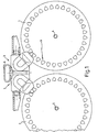
- Fig. 1 are two parallel stacked plates 1, 2 an air humidification device arranged thereon Drives 3 according to the invention in a schematic Side view shown.
- the plate stack 1, 2 exist z. B. from lamellar arranged one behind the other circular discs.
- the plate stack 1, 2 are in Air washers usually stored on a tub (not shown), in which there is usually water, if necessary with an additive in which the plate stack immerse when rotating around axes 4, 5.
- a housing cover on the z. B. a fan is arranged with a drive motor, which has an elastic Coupling 6 with two drives 3 in accordance with the invention Connection is established.
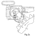
- the lever gear 7 is an arrangement with two drive levers 9, 10.
- the Drive levers 9, 10 each have a tooth shape configured tip 11, 12 and a receiving opening 13, 14 (See also Fig. 3a and b) for two drive pins 15, 16.
- the drive pins 15, 16 are on the two End faces of a worm wheel 17 eccentrically by 180 ° staggered and thus form an eccentric Bearing seat for it on the receiving openings 13, 14th attached drive lever 9, 10.
- the worm wheel 17 has an axis of rotation 18 in the housing of the lever mechanism 7 is mounted and is in engagement with a worm 19.
- the worm 19 is connected via the elastic coupling 6 with e.g. connected to a drive motor, not shown.
- a Rotation of the screw 19 and a rotation of the Worm wheel 17 e.g. in the direction of the arrow eccentric bearing seat 13, 14, 15, 16 of the drive lever 9, 10 this back and forth in the housing of the lever gear 7 moved or pivoted.
- the front drive lever 10 in shown by solid lines in engagement with the Teeth of the ring gear 8, while the second behind it arranged drive lever 9 (in dashed lines shown) completely from the toothing of the ring gear 8 withdrawn.
- the desired movement of the tooth-shaped Tips 11, 12 of the drive lever 9, 10 results in Essentially from the geometric distances of the eccentric arranged drive pin 15, 16 and the shape and Distance of the guide surfaces 20, 21.
- the trajectory of the tooth-shaped tips 11, 12 is the coupling curve of the thus realized push crank drive.
- teeth 22 of the ring gear 8 and the tooth-shaped tip 11, 12 is designed so that the interlocking teeth exemplify one Realize cycloid gearing.
- the movement the drive lever 9, 10 through the eccentric bearing as well the guide surfaces on the housing of the lever gearbox so coordinated that the tooth flanks roll on each other.
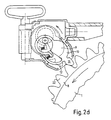
- the drive lever 10 is an example in FIGS. 3a to c shown again in detail.
- the outer contour of the Drive lever 10 is on a large area Side formed as a narrow frame 23. Before the Receiving opening 13, the frame 23 is interrupted and points Locating pin 24 for a compression spring 25 (only in Fig. 3a shown). This way the front area of the Drive lever 10 on this side resilient. This allows the drive lever 10 or the same Drive lever 9 with bias in the housing of Use lever gear 7. This prevents occurring manufacturing tolerances the lever 9, 10 a game that, if necessary, leads to the tip 11, 12 of a drive lever 9, 10 with a tooth of the ring gear 8 collided or hooked. Because of the asymmetrical Frame formation is achieved that the lever on a Can support the guide surface without giving in. This is preferably the side that has the essential forces for the Continues movement of the gear.
- the tips 11, 12 the drive lever 9, 10 directed downwards downward, so that liquid by immersing the ring gear 8 conveyed to the lever tips 11, 12 in a liquid bath will run back down to the ring gear 8.
- the device is disassembled for cleaning work for the layperson in a simple way, since with the acceptance of the Cover (not shown) just the stack of plates 1, 2 are in the tub (not shown).
- the drive shown for a plate stack 1, 2 can itself outside of an invention Use a humidifier.
- the system shown can be easily applied to any rotating object apply, in which a drive system according to the invention Offers advantages. This can be especially true with chemical Production facilities, where rolls, Drums, heat exchangers or the like within one Have to turn the liquid bath and thus that too Problem is that the drive is not or only with point the possibly aggressive liquid in contact may come.
- the drive principle according to the invention can also be used advantageously when a very large Ratio between the drive shaft and the rotating Object to be realized.
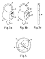
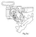
- 5a and b is a variant of an inventive Drive shown, instead of two drive levers three drive levers 26, 27, 28 are used. In correspondingly, drive pins are on one Worm gear 29 not eccentric by 180 ° but by 120 ° added.
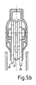
- Fig. 5b Clarification of the position of the drive lever 26, 27, 28 in Longitudinal section is shown, an even improved Achieve synchronism.
Abstract
Description
Die Erfindung betrifft einen Antrieb für einen rotierenden
Gegenstand nach dem Oberbegriff des Anspruchs 1.The invention relates to a drive for a rotating
Subject according to the preamble of
Ein solcher Antrieb ist bereits durch die europäische Offenlegungsschrift EP 083 8610 A2 bekanntgeworden. Das Kernstück dieses Antriebs ist mindestens ein schwenkbar gelagerter Hebel, der mit einem Zahnrad zusammenwirkt, das drehfest mit dem rotierenden Gegenstand verbundenen ist. Hierzu ist eine Vorrichtung zur Lagerung und Führung des Hebels für eine in das Zahnrad eingreifende und mitnehmende Vorwärtsbewegung des Hebels vorhanden.Such a drive is already through the European one Published publication EP 083 8610 A2. The The centerpiece of this drive is at least one swiveling mounted lever that cooperates with a gear that is non-rotatably connected to the rotating object. For this purpose, a device for storing and guiding the Lever for an engaging and entraining in the gear Forward movement of the lever is present.
Dieser Antrieb hat den Vorteil, daß er im Wesentlichen unempfindlich gegenüber Verunreinigungen ist, die durch eine Flüssigkeit auftreten, in welcher Walzen, Wellen oder dergleichen in einem Luftbefeuchtungs- und Reinigungsgerät, einem Duftverdunster oder dergleichen rotiert. Denn selbst wenn das Zahnrad hierbei durch die Rotationsbewegung in der Flüssigkeit von dieser benetzt wird, besteht der einzige Berührungspunkt mit den weiteren Getriebekomponenten in dem Teil des Hebels, der in das Zahnrad eingreift. Dieser Teil des Hebels ist jedoch in der Regel einfach zu reinigen.This drive has the advantage that it is essentially is insensitive to contamination caused by a Liquid occur in which rollers, shafts or the like in an air humidifying and cleaning device, a fragrance evaporator or the like rotates. Because itself if the gear is rotated in the Liquid is wetted by this is the only one Point of contact with the other gear components in the Part of the lever that engages the gear. this part the lever is usually easy to clean.
Ein Nachteil dieses Mechanismus besteht jedoch darin, daß insbesondere durch Auftreten von Fertigungstoleranzen der Antriebsteile ein gleichmäßiger geräuscharmer Lauf des rotierenden Gegenstandes mitunter beeinträchtigt ist, da insbesondere der im Eingriff stehende Hebel mit dem Zahnrad verhaken kann.A disadvantage of this mechanism, however, is that in particular by the occurrence of manufacturing tolerances Drive parts a smooth, quiet running of the rotating object is sometimes impaired because especially the engaged lever with the gear can get caught.
Der Erfindung liegt die Aufgabe zugrunde einen Antrieb zu schaffen, der einen verbesserten Gleichlauf aufweist und insbesondere unempfindlicher gegenüber Fertigungstoleranzen ist.The invention is based on the object of a drive create, which has an improved synchronization and in particular less sensitive to manufacturing tolerances is.
Diese Aufgabe wird durch die Merkmale des Anspruchs 1 gelöst.This object is solved by the features of
In den Unteransprüchen sind vorteilhafte und zweckmäßige Weiterbildungen des erfindungsgemäßen Antriebs angegeben.In the subclaims are advantageous and expedient Developments of the drive according to the invention specified.
Die Erfindung geht von einem Antrieb für einen rotierenden Gegenstand für eine Walze, Welle, Platte oder dergleichen, insbesondere für einen Duftverdunster, einen Luftbefeuchter oder ein Luftreinigungsgerät oder dergleichen aus, das die folgenden Merkmale aufweist:The invention is based on a drive for a rotating one Object for a roller, shaft, plate or the like, especially for a fragrance evaporator, a humidifier or an air purifier or the like made of has the following characteristics:
Einen beweglich gelagerten Hebel, ein Zahnrad, das drehfest mit dem rotierenden Gegenstand verbunden ist sowie ein Hebelgetriebe für eine in das Zahnrad eingreifende und mitnehmende Bewegung des Hebels zur Drehung des Zahnrades, wobei der Hebel zum Eingriff in die Zähne des Zahnrads eine Spitze aufweist. Der Kerngedanke der Erfindung liegt nun darin, daß die Spitze in Form eines Zahnes ausgebildet ist, wobei die Form dieses Zahnes und die der Zähne des Zahnrades sowie das Hebelgetriebe derart aufeinander abgestimmt sind, daß die Zahnflanken des Zahnes am wenigstens einen Hebel und des jeweils im Eingriff stehenden Zahnes am Zahnrad bei der mitnehmenden Bewegung aufeinander abwälzen. Durch diese Maßnahme wird erreicht, daß der Antrieb auch bei Auftreten von Fertigungstoleranzen das Zahnrad und den rotierenden Gegenstand in eine gleichmäßige Bewegung versetzt, wobei ein Verhaken von Hebelspitze und Zahnrad vermieden werden kann. Denn durch die erfindungsgemäße Ausgestaltung werden im Wesentlichen die Gesetzmäßigkeiten einer herkömmlichen Verzahnung zwischen zwei Zahnrädern erfüllt. Hierdurch wird außerdem der Verschleiß der sich berührenden Zahnflanken im Vergleich zur Lösung aus dem Stand der Technik deutlich verbessert, da die sonst vorhandene Gleitbewegung zwischen den Flanken stark herabgesetzt ist, und im Wesentlichen durch eine Abrollbewegung ersetzt wird. Dies macht sich insbesondere bei der Lebensdauer des Antriebs und beim Betriebsgeräusch positiv bemerkbar.A movably mounted lever, a gear that rotates is connected to the rotating object and a Lever gear for a meshing and entraining movement of the lever to rotate the gear, the lever for engaging the teeth of the gear a Has tip. The main idea of the invention is now in that the tip is in the form of a tooth, the shape of this tooth and that of the teeth of the gear and the lever gear are matched to one another in such a way that the tooth flanks of the tooth on at least one lever and of the currently engaged tooth on the gear at the Transfer driving movement on each other. Through this Measure is achieved that the drive also occurs of manufacturing tolerances the gear and the rotating Item in steady motion, being a Jamming of the lever tip and gear can be avoided. Because by the inventive design in Essentially the laws of a conventional one Gearing between two gears fulfilled. This will also the wear of the tooth flanks in contact Comparison to the solution from the prior art clearly improved because the otherwise existing sliding movement between the flanks is greatly reduced, and essentially by a rolling motion is replaced. This is clear especially in the life of the drive and Operating noise noticeably noticeable.
Um den Gleichlauf des Antriebs noch weiter zu verbessern, wird überdies vorgeschlagen, daß die Form des Zahnes am Hebel und die der Zähne des Zahnrades sowie das Hebelgetriebe derart aufeinander abgestimmt sind, daß die Zahnflanken des Zahnes am wenigstens einen Hebel und des jeweils im Eingriff stehenden Zahnes am Zahnrad bei der mitnehmenden Bewegung einen Berührungspunkt aufweisen, in dem die Flanken ohne radiales Gleiten aufeinander abrollen (Wälzpunkt).To further improve the synchronization of the drive, it is also proposed that the shape of the tooth on the lever and that of the teeth of the gear and the lever gear are coordinated so that the tooth flanks of the Tooth on at least one lever and each in engagement stationary tooth on the gearwheel during the entraining movement have a point of contact in which the flanks without Roll radial sliding on each other (pitch point).
Vorzugsweise ist die Form des Zahnes am Hebel und die der Zähne am Zahnrad nach den Regeln der Verzahnung als Evolventen-, Zykloiden-, Kreisbogen- oder als Triebstockverzahnung, bei welcher der Zahn am Hebel z.B. die Gestalt eines Zapfens besitzt, ausgebildet. Auf diese Weise läßt sich ein im Wesentlichen konstantes Übersetzungsverhältnis zwischen Hebelgetriebe und Zahnrad realisieren. Preferably, the shape of the tooth on the lever and that of Teeth on the gear according to the rules of gearing as Involute, cycloid, circular or as Triebstock toothing, in which the tooth on the lever e.g. the Has the shape of a pin, trained. In this way can be an essentially constant Gear ratio between lever gear and gear realize.
In einer besonders vorteilhaften Ausgestaltung der Erfindung beinhaltet das Hebelgetriebe zur Schubführung des Hebels Führungsflächen für den Hebel. Dadurch kann der Hebel geführt beispielsweise eine Vorwärtsbewegung, eine Rückwärtsbewegung sowie eine Schwenkbewegung durchführen. In diesem Zusammenhang ist es vorteilhaft, wenn das Hebelgetriebe einen Exzenterantrieb für den Hebel umfaßt. Durch eine entsprechend aufeinander abgestimmte geometrische Anordnung der Gelenkpunkte des Hebels und der Führungsflächen am Hebelgetriebegehäuse kann für den zyklischen Eingriff der zahnförmigen Spitze des wenigstens einen Hebels eine gewünschte Koppelkurve erreicht werden. Anstatt des dadurch realisierten Funktionsprinzips des Schubkurbelgetriebes kann in einer anderen Ausführungsform auch das Funktionsprinzip der Kurbelschleife angewandt werden, bei welchem sich die Längsführung im Hebel befindet, in die beispielsweise ein im Hebelgetriebegehäuse festgelegter Zapfen eingreift.In a particularly advantageous embodiment of the invention includes the lever mechanism for pushing the lever Guide surfaces for the lever. This allows the lever to be guided for example a forward movement, a backward movement as well as perform a swivel movement. In this Context, it is advantageous if the lever mechanism one Eccentric drive for the lever includes. By a corresponding coordinated geometric arrangement of the Pivot points of the lever and the guide surfaces on Lever gearbox can be used for the cyclical engagement tooth-shaped tip of the at least one lever desired coupling curve can be achieved. Instead of that realized functional principle of the thrust crank gear can in another embodiment, the principle of operation the crank loop, in which the Longitudinal guide is located in the lever, for example in the Lever gear housing engages fixed pin.
Zur Realisierung eines einfachen Exzenterantriebs wird im weiteren vorgeschlagen, daß dieser eine Antriebswelle für den Hebel aufweist, die exzentrisch auf einem Zahnrad angeordnet ist. Das Zahnrad kann kontinuierlich angetrieben werden, vorzugsweise mit Hilfe einer Schnecke. Hierdurch sind zum einen extreme Übersetzungen möglich, was insbesondere bei der Verwendung in einem erfindungsgemäßen Duftverdunster oder Luftwäscher, wo nur ein Motor zum direkten Antrieb des Ventilators und Antrieb eines oder zweier Plattenstapel eingesetzt wird, notwendig ist. Zum anderen stellt ein Schneckengetriebe ein sogenanntes selbsthemmendes Getriebe dar, wodurch der wenigstens eine Hebel gegen eine unerwünschte Bewegung blockiert ist.To implement a simple eccentric drive, further suggested that this be a drive shaft for the Has lever, which is arranged eccentrically on a gear is. The gear can be driven continuously preferably with the help of a snail. This means that extreme translations possible, which is particularly the case with Use in a fragrance evaporator according to the invention or Air washer where only one motor drives the Fan and drive one or two stacks of plates is used is necessary. On the other hand, hires Worm gear a so-called self-locking gear represents, whereby the at least one lever against one unwanted movement is blocked.
In einer bevorzugten Ausführungsform wird die Antriebswelle direkt exzentrisch auf einem Zahnrad angebracht, welches von einer Schnecke angetrieben wird. In a preferred embodiment, the drive shaft mounted directly eccentrically on a gearwheel, which from a worm is driven.
Vorzugsweise wird die Schnecke über eine elastische Kupplung mit der Antriebswelle eines Motors verbunden. Hierdurch braucht die Antriebswelle nicht vollständig exakt in Flucht mit der Schneckenwelle zu stehen. Größere Toleranzen bei der Fertigung eines erfindungsgemäßen Antriebs sind hierbei möglich, was unter anderem eine Kostenersparnis mit sich bringt.The worm is preferably connected via an elastic coupling connected to the drive shaft of a motor. hereby the drive shaft does not need to be completely in line to stand with the worm shaft. Larger tolerances in the Manufacture of a drive according to the invention are here possible, which among other things a cost saving brings.
In einer besonders vorteilhaften Ausgestaltung der Erfindung sind zwei, drei oder mehr Hebel vorgesehen, die abwechselnd in das Zahnrad eingreifen. Dadurch befindet sich ständig mindestens ein Hebel im Eingriff mit dem Zahn- bzw. Zapfenkranz des rotierenden Gegenstandes, so daß dieser gleichmäßig angetrieben wird. Des Weiteren wird insbesondere für den Fall gewährleistet, daß die Hebel durch ein Schneckengetriebe gegen eine unerwünschte Bewegung verriegelt sind, daß auch der rotierende Gegenstand durch wenigstens einen im Eingriff befindlichen Hebel gegen jede unerwünschte weitere Bewegung, beispielsweise gegen ein Zurückdrehen gesichert ist. Die Rotation des rotierenden Gegenstandes ist somit ständig mechanisch fest durch den Hebelantrieb kontrolliert.In a particularly advantageous embodiment of the invention two, three or more levers are provided, which alternate engage the gear. As a result, is constantly at least one lever in engagement with the tooth or Cone of the rotating object, so that this is driven evenly. Furthermore, in particular in the event that the lever by a Worm gear locked against unwanted movement are that the rotating object by at least an engaged lever against any unwanted further movement, for example against turning back is secured. The rotation of the rotating object is thus always mechanically fixed by the lever drive controlled.
Im weiteren ist es besonders bevorzugt, wenn der wenigstens eine Hebel zwischen den Führungsflächen des Hebelgetriebes elastisch gelagert ist. Dadurch wird der Hebel im Hebelgetriebe vorgespannt und weist auch bei Fertigungstoleranzen kein Spiel auf. Ein zu großes Spiel könnte dazu führen, daß im schlimmsten Fall der Zahn eines eingreifenden Hebels mit einem Zahn des Zahnrades kollidiert oder sich die Zähne verhaken.Furthermore, it is particularly preferred if the at least a lever between the guide surfaces of the lever gear is mounted elastically. This will pull the lever in Lever gear biased and also has Manufacturing tolerances no play. Too big a game could lead to the worst case that the tooth of a engaging lever collides with a tooth of the gear or your teeth get caught.
Besonders bevorzugt ist es dabei, wenn zur elastischen Lagerung des Hebels zwischen den Führungsflächen wenigstens ein Teil der von den Führungsflächen erfaßten Außenkontur des Hebels elastisch nachgiebig ist. In diesem Zusammenhang ist es vorteilhaft, wenn zur Realisierung einer elastisch nachgiebigen Außenkontur des Hebels, die Außenkontur als schmaler Rahmen ausgebildet ist. Insbesondere, wenn der Hebel aus Kunststoff hergestellt ist, weist dadurch dieser Konturbereich federnde Eigenschaften auf.It is particularly preferred if the elastic Storage of the lever between the guide surfaces at least part of the outer contour of the guide surfaces Lever is resilient. In this context it is it is advantageous if to realize an elastic compliant outer contour of the lever, the outer contour as narrow frame is formed. Especially when the lever is made of plastic, this has Contour area resilient properties.
Um die Federeigenschaften noch zu verbessern, ist es darüber hinaus bevorzugt, wenn der Rahmen unterbrochen ist, wobei in die Unterbrechungsstelle ein Federelement eingesetzt ist.To improve the spring properties even more, it is above preferred also when the frame is interrupted, wherein in the interruption point a spring element is inserted.
Um eine effektive Kraftübertragung des wenigstens einen Hebels auf das Zahnrad zu gewährleisten, wird schließlich vorgeschlagen, daß der Bereich der Außenkante des Hebels nicht elastisch nachgiebig ist, der sich zur Aufnahme der wesentlichen Kraft für eine Weiterbewegung des Zahnrades an einer Führungsfläche des Hebelgetriebes abstützt.To ensure effective power transmission of the at least one Ensuring lever on the gear will eventually suggested that the area of the outer edge of the lever is not resilient, which is to accommodate the essential force for further movement of the gear a guide surface of the lever gear supports.
Mehrere Ausführungsbeispiele der Erfindung sind in den Zeichnungen dargestellt und in der nachfolgenden Beschreibung unter Angabe weiterer Vorteile und Einzelheiten näher erläutert. Es zeigen
- Fig. 1
- eine Seitenansicht von zwei nebeneinander angeordneten Plattenstapel eines Luftbefeuchtungsgerätes mit jeweils daran angeordneten erfindungsgemäßen Antrieben in einer schematischen Seitenansicht,
- Fig. 2a-e
- einen Ausschnitt eines erfindungsgemäßen Antriebs gemäß Fig. 1 im schematischen Querschnitt für verschiedene Hebelpositionen,
- Fig. 3a-c
- einen erfindungsgemäßen Hebel in zwei Draufsichten mit und ohne Federelement sowie einer Seitenansicht,
- Fig. 4
- ein Schneckenrad mit exzentrisch angeordneter Antriebswelle für einen Hebel gemäß Fig. 3a bis c in einer schematischen Draufsicht,
- Fig. 5a
- einen Ausschnitt eines erfindungsgemäßen Antriebs entsprechend der Figuren 2a bis e jedoch mit drei Antriebshebeln für eine Position und
- Fig. 5b
- einen erfindungsgemäßen Antrieb gemäß Fig. 5a im Längsschnitt.
- Fig. 1
- 2 shows a side view of two stacked plates of an air humidification device, each with drives according to the invention arranged thereon, in a schematic side view,
- 2a-e
- 1 shows a section of a drive according to the invention according to FIG. 1 in a schematic cross section for different lever positions,
- 3a-c
- a lever according to the invention in two top views with and without spring element and a side view,
- Fig. 4
- a worm wheel with an eccentrically arranged drive shaft for a lever according to FIGS. 3a to c in a schematic plan view,
- Fig. 5a
- a section of a drive according to the invention according to Figures 2a to e but with three drive levers for one position and
- Fig. 5b
- an inventive drive according to FIG. 5a in longitudinal section.
In Fig. 1 sind zwei parallel gelagerte Plattenstapel 1, 2
eines Luftbefeuchtungsgerätes mit daran angeordneten
erfindungsgemäßen Antrieben 3 in einer schematischen
Seitenansicht dargestellt. Die Plattenstapel 1, 2 bestehen z.
B. aus lammellenförmig hintereinander angeordneten
kreisförmigen Scheiben. Die Plattenstapel 1, 2 sind im
Luftwäscher normalerweise an einer Wanne gelagert (nicht
dargestellt), in der sich in der Regel Wasser, gegebenenfalls
mit einem Zusatzstoff befindet, in welches die Plattenstapel
bei einer Drehung um Achsen 4, 5 eintauchen. Ebenfalls nicht
dargestellt ist ein Gehäusedeckel an dem z. B. ein Ventilator
mit Antriebsmotor angeordnet ist, der über eine elastische
Kupplung 6 mit beiden erfindungsgemäßen Antrieben 3 in
Verbindung steht. In Fig. 1 are two parallel
In den Fig. 2a der e ein der erfindungsgemäßer Antrieb 3
ausschnittsweise vergrößert und im Schnittbild für
verschiedene Hebelpositionen dargestellt. Diese Figuren
zeigen ein Hebelgetriebe 7, das mit einem Zahnkranz 8
zusammenwirkt, der an der Stirnseite des Plattenstapels 1
angeordnet ist. Bei dem Hebelgetriebe 7 handelt es sich um
eine Anordnung mit zwei Antriebshebeln 9, 10. Die
Antriebshebel 9, 10 besitzen jeweils eine zahnförmig
ausgestaltete Spitze 11, 12 sowie eine Aufnahmeöffnung 13, 14
(siehe auch Fig. 3a und b) für jeweils zwei Antriebszapfen
15, 16. Die Antriebszapfen 15, 16 sind an den beiden
Stirnflächen eines Schneckenrades 17 exzentrisch um 180°
versetzt angebracht und bilden somit einen exzentrischen
Lagersitz für die darauf über die Aufnahmeöffnungen 13, 14
aufgesteckten Antriebshebel 9, 10. Das Schneckenrad 17
besitzt eine Drehachse 18, die im Gehäuse des Hebelgetriebes
7 gelagert ist und steht mit einer Schnecke 19 in Eingriff.
Die Schnecke 19 ist über die elastische Kupplung 6 mit z.B.
einem nicht gezeigten Antriebsmotor verbunden. Bei einer
Drehung der Schnecke 19 und einer damit bewirkten Drehung des
Schneckenrades 17 z.B. in Pfeilrichtung werden über den
exzentrischen Lagersitz 13, 14, 15, 16 der Antriebshebel 9,
10 diese im Gehäuse des Hebelgetriebes 7 vor und zurück
bewegt bzw. geschwenkt. Dabei liegt die Außenkontur der
Antriebshebel 9, 10 an Führungsflächen 20, 21 des Gehäuses
des Hebelgetriebes 7 an.2a of the drive 3 according to the invention
Enlarged in parts and in the sectional view for
different lever positions are shown. These figures
show a lever gear 7 with a ring gear 8th
interacts, which on the end face of the
In Fig. 2a ist der vordere Antriebshebel 10 (in
durchgezogenen Linien dargestellt) im Eingriff mit der
Verzahnung des Zahnkranzes 8, während der zweite dahinter
angeordnete Antriebshebel 9 (in gestrichelten Linien
dargestellt) völlig aus der Verzahnung des Zahnkranzes 8
zurückgenommen ist. Die gewünschte Bewegung der zahnförmigen
Spitzen 11, 12 der Antriebshebel 9, 10 ergibt sich im
Wesentlichen aus den geometrischen Abständen der exzentrisch
angeordneten Antriebszapfen 15, 16 sowie der Form und dem
Abstand der Führungsflächen 20, 21. Die Bahnkurve der
zahnförmigen Spitzen 11, 12 stellt sich als Koppelkurve des
somit realisierten Schubkurbelantriebs dar.2a, the front drive lever 10 (in
shown by solid lines) in engagement with the
Teeth of the ring gear 8, while the second behind it
arranged drive lever 9 (in dashed lines
shown) completely from the toothing of the ring gear 8
withdrawn. The desired movement of the tooth-shaped
Die Bewegung der Antriebshebel 9, 10 zur Erzielung einer
Drehbewegung des am Plattenstapel 1 angeordneten Zahnkranzes
8 in Pfeilrichtung ist in unterschiedlichen Winkelpositionen
des Schneckenrades 17 in den Figuren 2a bis e abgebildet.
Dabei entspricht jede Figur einem Zustand der Hebelposition
für eine Drehung des Schneckenrades 17 um 45°. D.h. Fig. 2e
stellt eine Drehung um 180° dar, sofern Fig. 2a mit 0°
festgelegt wird.The movement of the
Die Form von Zähnen 22 des Zahnkranzes 8 sowie der
zahnförmigen Spitze 11, 12 ist so ausgebildet, daß die
ineinander greifenden Zähne beispielhaft eine
Zykloidenverzahnung realisieren. Außerdem ist die Bewegung
der Antriebshebel 9, 10 durch die exzentrische Lagerung sowie
die Führungsflächen am Gehäuse des Hebelgetriebes so
abgestimmt, daß die Zahnflanken aufeinander abwälzen.The shape of
In den Figuren 3a bis c ist beispielhaft der Antriebshebel 10
nochmals im einzelnen dargestellt. Die Außenkontur des
Antriebshebels 10 ist über einen großen Bereich auf einer
Seite als schmaler Rahmen 23 ausgebildet. Vor der
Aufnahmeöffnung 13 ist der Rahmen 23 unterbrochen und weist
Aufnahmezapfen 24 für eine Druckfeder 25 (nur in Fig. 3a
dargestellt) auf. Auf diese Weise ist der vordere Bereich des
Antriebshebels 10 auf dieser Seite elastisch nachgiebig. Dies
ermöglicht, den Antriebshebel 10 oder dem gleich gestalteten
Antriebshebel 9 mit Vorspannung in das Gehäuse des
Hebelgetriebes 7 einzusetzen. Damit wird verhindert, daß bei
auftretenden Fertigungstoleranzen die Hebel 9, 10 ein Spiel
aufweisen, daß gegebenenfalls dazu führt, daß die Spitze 11,
12 eines Antriebshebels 9, 10 mit einem Zahn des Zahnkranzes
8 kollidiert oder verhakt. Durch die unsymmetrische
Rahmenbildung wird erreicht, daß sich der Hebel an einer
Führungsfläche ohne nachzugeben abstützen kann. Dies ist
vorzugsweise die Seite, die die wesentlichen Kräfte für die
Weiterbewegung des Zahnrades aufnimmt.The
In Fig. 4 ist das Schneckenrad 17 mit den an beiden
Stirnseiten exzentrisch um 180° versetzt angeordneten
Antriebszapfen 15, 16 nochmals als Einzelheit dargestellt.
Wie bereits oben erwähnt erfolgt die Lagerung des
Schneckenrads 17 über Lagerachsen 18, die aus den exzentrisch
angeordneten Antriebswellen 15, 16 herausragen.In Fig. 4, the
Wie insbesondere aus Fig. 1 ersichtlich, sind die Spitzen 11,
12 der Antriebshebel 9, 10 nach unten abwärts gerichtet, so
daß Flüssigkeit, die durch das Eintauchen des Zahnkranzes 8
in ein Flüssigkeitsbad zu den Hebelspitzen 11, 12 gefördert
wird, wieder hinunter zum Zahnkranz 8 abläuft. Die einzigen
Stellen, die also mit der Flüssigkeit des Bades in Verbindung
kommen können, sind lediglich die zahnförmigen Spitzen 11, 12
der Antriebshebel 9, 10. Es besteht somit keine Gefahr, daß
die restlichen Komponenten des Antriebs in irgendeiner Phase
des Betriebs des Geräts mit der Badflüssigkeit in Berührung
kommen. Eine Zerlegung des Geräts für Reinigungsarbeiten ist
für den Laien in einfacher Weise möglich, da mit Abnahme des
Deckels (nicht dargestellt) sich nur noch die Plattenstapel
1, 2 in der Wanne (nicht dargestellt) befinden.As can be seen in particular from FIG. 1, the
Der dargestellte Antrieb für einen Plattenstapel 1, 2 läßt
sich auch außerhalb eines erfindungsgemäßen
Luftbefeuchtungsgeräts einsetzen. Das dargestellte System
läßt sich ohne weiteres auf jeden rotierenden Gegenstand
anwenden, bei dem ein erfindungsgemäßes Antriebssystem
Vorteile bietet. Dies kann insbesondere bei chemischen
Produktionsanlagen der Fall sein, wo ebenfalls häufig Walzen,
Trommeln, Wärmetauscher oder dergleichen innerhalb eines
Flüssigkeitsbades drehen müssen und somit sich ebenfalls das
Problem stellt, daß der Antrieb nicht oder nur punkutell mit
der gegebenenfalls aggressiven Flüssigkeit in Berührung
kommen darf. Auch kann das erfindungsgemäße Antriebsprinzip
vorteilhaft angewendet werden, wenn eine sehr große
Übersetzung zwischen der Antriebswelle und dem rotierenden
Gegenstand zu realisieren ist.The drive shown for a
In Fig. 5a und b ist eine Variante eines erfindungsgemäßen
Antriebs dargestellt, bei dem anstatt zweier Antriebshebel
drei Antriebshebel 26, 27, 28 verwendet werden. In
entsprechender Weise sind Antriebszapfen auf einem
Schneckenrad 29 nicht um 180° sondern um 120° exzentrisch
versetzt. Durch diese Ausführungsform, die in Fig. 5b zur
Verdeutlichung der Lage der Antriebshebel 26, 27, 28 im
Längsschnitt dargestellt ist, läßt sich ein noch verbesserter
Gleichlauf erzielen. 5a and b is a variant of an inventive
Drive shown, instead of two drive levers
three
- 11
- Plattenstapelplate stack
- 22
- Plattenstapelplate stack
- 33
- Antriebdrive
- 44
- Achseaxis
- 55
- Achseaxis
- 66
- elastische Kuppelelastic dome
- 77
- Hebelgetriebelever mechanism
- 88th
- Zahnkranzsprocket
- 99
- Antriebszapfendrive journal
- 1010
- Antriebszapfendrive journal
- 1111
- zahnförmige Spitzetooth-shaped tip
- 1212
- zahnförmige Spitzetooth-shaped tip
- 1313
- Aufnahmeöffnungreceiving opening
- 1414
- Aufnahmeöffnungreceiving opening
- 1515
- Antriebszapfendrive journal
- 1616
- Antriebszapfendrive journal
- 1717
- Schneckenradworm
- 1818
- Achseaxis
- 1919
- Schneckeslug
- 2020
- Führungsflächeguide surface
- 2121
- Führungsflächeguide surface
- 2222
- Zahntooth
- 2323
- Rahmenframe
- 2424
- Zapfenspigot
- 2525
- Druckfedercompression spring
- 2626
- Antriebshebeldrive lever
- 2727
- Antriebshebeldrive lever
- 2828
- Antriebshebeldrive lever
- 2929
- Schneckenradworm
Claims (14)
- Drive mechanism for a rotating object, such as a roller, shaft, plate or the like, in particular for a fragrance vaporiser, an air humidifier or an air purifier or the like, with at least one movably mounted lever, a gear wheel (8) non-rotatably connected to the rotating object, and with a lever mechanism (7) for a movement of the lever engaging and entraining the gear wheel to rotate the gear wheel, the lever having a tip (11, 12) to engage in the teeth of the gear wheel, characterised in that the tip (11, 12) is designed in the form of a tooth, the form of this tooth and that of the teeth of the gear wheel (8) and the lever mechanism (7) being coordinated with each other in such a way that the tooth flanks of the tooth (11, 12) on the at least one lever (9, 10) and of the respectively engaged tooth (22) on the gear wheel roll off each other during the entraining movement.
- Drive mechanism according to claim 1, characterised in that the form of the tooth (11, 12) on at least one lever (9, 10) and that of the teeth (22) of the gear wheel (8) and the lever mechanism (7) are coordinated with one another in such a way that the tooth flanks of the tooth on at least one lever (9, 10) and of the respectively engaged tooth (21) on the gear wheel (8) during the entraining movement have a contact point in which the tooth flanks roll off each other substantially without radial sliding.
- Driving mechanism according to either of claims 2 or 3, characterised in that the form of the tooth on the lever (9, 10) and of the teeth (22) of the gear wheel (8) is designed according to the rules of toothing of an involute, cycloidal, round-flank, or pin wheel toothing.
- Drive mechanism according to any one of the preceding claims, characterised in that the lever mechanism (7) contains guide faces (20, 21) for the thrust guidance of the lever (9, 10).
- Drive mechanism according to claim 4, characterised in that the lever mechanism (7) comprises an eccentric drive for the lever (9, 10).
- Drive mechanism according to claim 5, characterised in that the eccentric drive comprises a drive shaft (15, 16) for the lever, which drive shaft (15, 16) is arranged eccentrically on a gear wheel.
- Drive mechanism according to claim 6, characterised in that the gear wheel is a worm wheel (17), in which a worm (19) engages.
- Drive mechanism according to claim 7, characterised in that the worm (19) is connected to the drive shaft of a motor via a resilient coupling.
- Drive mechanism according to any one of the preceding claims, characterised in that there are two, three or more levers (9, 10; 26, 27, 28).
- Drive mechanism, in particular according to any one of the preceding claims 4 to 9, characterised in that the lever (9, 10) is resiliently mounted between the guide faces (20, 21) of the lever mechanism (7).
- Drive mechanism according to claim 10, characterised in that at least part of the external contour of the lever grasped by the guide faces is resiliently flexible for resilient mounting of the lever (9, 10) between the guide faces (20, 21).
- Drive mechanism according to claim 11, characterised in that the external contour is designed as a narrow frame (23) to produce a resiliently flexible external contour of the lever (9, 10).
- Drive mechanism according to claim 12, characterised in that the frame (23) is interrupted, a spring element (25) being inserted into the interruption point.
- Drive mechanism according to any one of claims 10 to 13, characterised in that the region of the external contour of the lever which is supported on a guide face (20) to receive the substantial force for further movement of the gear wheel, is not resiliently flexible.
Applications Claiming Priority (3)
| Application Number | Priority Date | Filing Date | Title |
|---|---|---|---|
| US09/222,726 US6318203B1 (en) | 1998-12-29 | 1998-12-29 | Drive for rotating object such as a roller, shaft, plate or the like |
| US222726 | 1998-12-29 | ||
| PCT/IB1999/002063 WO2000039485A1 (en) | 1998-12-29 | 1999-12-29 | Drive mechanism for a rotating object such as a roller, shaft, disk or such like |
Publications (2)
| Publication Number | Publication Date |
|---|---|
| EP1141583A1 EP1141583A1 (en) | 2001-10-10 |
| EP1141583B1 true EP1141583B1 (en) | 2003-07-30 |
Family
ID=22833425
Family Applications (1)
| Application Number | Title | Priority Date | Filing Date |
|---|---|---|---|
| EP99959636A Expired - Lifetime EP1141583B1 (en) | 1998-12-29 | 1999-12-29 | Drive mechanism for a rotating object such as a roller, shaft, disk or such like |
Country Status (10)
| Country | Link |
|---|---|
| US (1) | US6318203B1 (en) |
| EP (1) | EP1141583B1 (en) |
| JP (1) | JP4540852B2 (en) |
| KR (1) | KR100646717B1 (en) |
| CN (1) | CN1099534C (en) |
| AT (1) | ATE246321T1 (en) |
| CA (1) | CA2347672C (en) |
| DE (2) | DE19958078A1 (en) |
| NO (1) | NO320077B1 (en) |
| WO (1) | WO2000039485A1 (en) |
Cited By (1)
| Publication number | Priority date | Publication date | Assignee | Title |
|---|---|---|---|---|
| EP1647322A2 (en) | 2004-10-15 | 2006-04-19 | Edgar Emele Kunststofftechnik Präzisionsformen GmbH & Co. KG | Scrubber for cleaning or humidifying air |
Families Citing this family (6)
| Publication number | Priority date | Publication date | Assignee | Title |
|---|---|---|---|---|
| US9662747B2 (en) | 2006-09-13 | 2017-05-30 | Hypertherm, Inc. | Composite consumables for a plasma arc torch |
| US9560732B2 (en) | 2006-09-13 | 2017-01-31 | Hypertherm, Inc. | High access consumables for a plasma arc cutting system |
| US10194516B2 (en) | 2006-09-13 | 2019-01-29 | Hypertherm, Inc. | High access consumables for a plasma arc cutting system |
| US10098217B2 (en) | 2012-07-19 | 2018-10-09 | Hypertherm, Inc. | Composite consumables for a plasma arc torch |
| KR20160115305A (en) | 2015-03-26 | 2016-10-06 | 진정현 | An Apparatus Collecting Oil for Vehicle |
| KR20200095099A (en) | 2019-01-31 | 2020-08-10 | 길은미 | An apparatus collecting oil for vehicle |
Family Cites Families (11)
| Publication number | Priority date | Publication date | Assignee | Title |
|---|---|---|---|---|
| FR989820A (en) * | 1949-04-30 | 1951-09-13 | Gear reduction mechanism | |
| DE2011245A1 (en) * | 1970-03-10 | 1971-09-23 | Zahnradfabrik Friedrichshafen Ag, 7990 Friedrichshafen | Involute helical toothing for spur gears with external and internal toothing, and tools for finishing |
| US3738185A (en) * | 1971-04-26 | 1973-06-12 | Scott & Fetzer Co | Sequential timer |
| US3834680A (en) * | 1972-06-12 | 1974-09-10 | W Walker | Air conditioning apparatus for a vehicle cab |
| US4261930A (en) * | 1976-06-14 | 1981-04-14 | Byco Sales, Ltd. | Evaporative cooling system |
| DE3608367A1 (en) * | 1986-03-13 | 1987-09-17 | Ako Werke Gmbh & Co | DRIVE DEVICE OF A PROGRAM SWITCHGEAR |
| JP2515645Y2 (en) * | 1989-11-21 | 1996-10-30 | アスモ 株式会社 | Motor with reduction gear |
| EP0783656B1 (en) * | 1994-10-17 | 1999-01-20 | Venta Vertriebs Ag | Fragrance evaporator, in particular for toilets |
| DE4441105A1 (en) | 1994-10-17 | 1996-04-18 | Venta Vertriebs Ag | Fragrance evaporator, especially for toilets |
| JP3091383B2 (en) * | 1995-02-17 | 2000-09-25 | 株式会社東海理化電機製作所 | Gear mechanism and webbing take-up device |
| US5802921A (en) * | 1996-08-13 | 1998-09-08 | Rouverol; William S. | Maximum power density gearing |
-
1998
- 1998-12-29 US US09/222,726 patent/US6318203B1/en not_active Expired - Lifetime
-
1999
- 1999-12-02 DE DE19958078A patent/DE19958078A1/en not_active Withdrawn
- 1999-12-29 KR KR1020017008255A patent/KR100646717B1/en active IP Right Grant
- 1999-12-29 DE DE59906459T patent/DE59906459D1/en not_active Expired - Lifetime
- 1999-12-29 AT AT99959636T patent/ATE246321T1/en not_active IP Right Cessation
- 1999-12-29 CA CA002347672A patent/CA2347672C/en not_active Expired - Fee Related
- 1999-12-29 CN CN99815162A patent/CN1099534C/en not_active Expired - Lifetime
- 1999-12-29 JP JP2000591349A patent/JP4540852B2/en not_active Expired - Lifetime
- 1999-12-29 EP EP99959636A patent/EP1141583B1/en not_active Expired - Lifetime
- 1999-12-29 WO PCT/IB1999/002063 patent/WO2000039485A1/en active IP Right Grant
-
2001
- 2001-03-07 NO NO20011145A patent/NO320077B1/en unknown
Cited By (1)
| Publication number | Priority date | Publication date | Assignee | Title |
|---|---|---|---|---|
| EP1647322A2 (en) | 2004-10-15 | 2006-04-19 | Edgar Emele Kunststofftechnik Präzisionsformen GmbH & Co. KG | Scrubber for cleaning or humidifying air |
Also Published As
| Publication number | Publication date |
|---|---|
| CN1099534C (en) | 2003-01-22 |
| DE19958078A1 (en) | 2000-07-06 |
| CA2347672C (en) | 2008-08-19 |
| CA2347672A1 (en) | 2000-07-06 |
| KR100646717B1 (en) | 2006-11-17 |
| CN1332830A (en) | 2002-01-23 |
| JP2002533636A (en) | 2002-10-08 |
| NO20011145D0 (en) | 2001-03-07 |
| JP4540852B2 (en) | 2010-09-08 |
| US6318203B1 (en) | 2001-11-20 |
| KR20010099994A (en) | 2001-11-09 |
| NO320077B1 (en) | 2005-10-17 |
| WO2000039485A1 (en) | 2000-07-06 |
| DE59906459D1 (en) | 2003-09-04 |
| ATE246321T1 (en) | 2003-08-15 |
| NO20011145L (en) | 2001-08-29 |
| EP1141583A1 (en) | 2001-10-10 |
Similar Documents
| Publication | Publication Date | Title |
|---|---|---|
| EP0981696B1 (en) | Eccentric toothed gear | |
| DE112007002103B4 (en) | Rolling element screw | |
| DE10133230A1 (en) | Wave transmission unit | |
| EP2933415B1 (en) | Door drive | |
| EP1626202A1 (en) | Reduction gearing and drive mechanism comprising the reduction gearing | |
| DE102019125310A1 (en) | Planetary gear | |
| EP1141583B1 (en) | Drive mechanism for a rotating object such as a roller, shaft, disk or such like | |
| DE3330204C2 (en) | Spur gear for driving a roll shell | |
| EP0004325A2 (en) | Improvements in and relating to locking devices for windows, doors and the like | |
| EP0075667A1 (en) | Positioner with a planetary reduction gear | |
| DE19914555A1 (en) | Multi-purpose planetary gear drive for an electric motor minimizes slip, friction, noise emissions and manufacturing costs | |
| DE3129648C2 (en) | Safety device against unintentional rolling of a roller shutter | |
| DE4215374C2 (en) | Motorized actuator | |
| DE3919613C2 (en) | ||
| DE19914556A1 (en) | Multi-purpose planetary gear drive for electric motor has fixed ring gear, rotating ring gear, flexible gear wheel, two planetary wheels and sun wheel powered input shaft | |
| DE69821561T2 (en) | Cable winch with offset drive | |
| WO2016198416A1 (en) | Microscope with friction drives | |
| EP0668973B1 (en) | Epicyclic roller gear with two rings having an inner profile and a rolling element capable of rolling on the inner side of the rings | |
| EP0838610B1 (en) | Drive for rotating device like a roll, shaft or similar | |
| DE10247439B4 (en) | Transmission for windscreen wiper device and windscreen wiper device, which is provided with such a transmission | |
| DE10030607A1 (en) | Gearbox for converting rotational movement into translation movement has linear gearing with two gearwheels on common shaft driven at different speeds with one secured to common shaft | |
| WO1999047781A1 (en) | Drive device for a hinged side window of a vehicle | |
| EP1573233A1 (en) | Gearing | |
| DE3106464C2 (en) | Eccentric gear for transferring a rotary movement in a step-up or step-down ratio of 1: 2 or 2: 1 | |
| EP1171728B1 (en) | Drive unit for a gearbox, especially for adjusting devices of motor vehicles |
Legal Events
| Date | Code | Title | Description |
|---|---|---|---|
| PUAI | Public reference made under article 153(3) epc to a published international application that has entered the european phase |
Free format text: ORIGINAL CODE: 0009012 |
|
| 17P | Request for examination filed |
Effective date: 20010222 |
|
| AK | Designated contracting states |
Kind code of ref document: A1 Designated state(s): AT BE CH CY DE DK ES FI FR GB GR IE IT LI LU MC NL PT SE |
|
| GRAG | Despatch of communication of intention to grant |
Free format text: ORIGINAL CODE: EPIDOS AGRA |
|
| 17Q | First examination report despatched |
Effective date: 20020102 |
|
| GRAG | Despatch of communication of intention to grant |
Free format text: ORIGINAL CODE: EPIDOS AGRA |
|
| GRAH | Despatch of communication of intention to grant a patent |
Free format text: ORIGINAL CODE: EPIDOS IGRA |
|
| GRAH | Despatch of communication of intention to grant a patent |
Free format text: ORIGINAL CODE: EPIDOS IGRA |
|
| GRAA | (expected) grant |
Free format text: ORIGINAL CODE: 0009210 |
|
| AK | Designated contracting states |
Designated state(s): AT CH DE LI NL SE |
|
| REG | Reference to a national code |
Ref country code: CH Ref legal event code: EP |
|
| REG | Reference to a national code |
Ref country code: IE Ref legal event code: FG4D Free format text: GERMAN |
|
| REF | Corresponds to: |
Ref document number: 59906459 Country of ref document: DE Date of ref document: 20030904 Kind code of ref document: P |
|
| REG | Reference to a national code |
Ref country code: CH Ref legal event code: NV Representative=s name: KATZAROV S.A. |
|
| REG | Reference to a national code |
Ref country code: SE Ref legal event code: TRGR |
|
| REG | Reference to a national code |
Ref country code: IE Ref legal event code: FD4D |
|
| PLBE | No opposition filed within time limit |
Free format text: ORIGINAL CODE: 0009261 |
|
| STAA | Information on the status of an ep patent application or granted ep patent |
Free format text: STATUS: NO OPPOSITION FILED WITHIN TIME LIMIT |
|
| 26N | No opposition filed |
Effective date: 20040504 |
|
| PGFP | Annual fee paid to national office [announced via postgrant information from national office to epo] |
Ref country code: SE Payment date: 20061213 Year of fee payment: 8 |
|
| PGFP | Annual fee paid to national office [announced via postgrant information from national office to epo] |
Ref country code: NL Payment date: 20071213 Year of fee payment: 9 |
|
| PGFP | Annual fee paid to national office [announced via postgrant information from national office to epo] |
Ref country code: AT Payment date: 20071213 Year of fee payment: 9 |
|
| EUG | Se: european patent has lapsed | ||
| PG25 | Lapsed in a contracting state [announced via postgrant information from national office to epo] |
Ref country code: SE Free format text: LAPSE BECAUSE OF NON-PAYMENT OF DUE FEES Effective date: 20071230 |
|
| PG25 | Lapsed in a contracting state [announced via postgrant information from national office to epo] |
Ref country code: AT Free format text: LAPSE BECAUSE OF NON-PAYMENT OF DUE FEES Effective date: 20081229 |
|
| NLV4 | Nl: lapsed or anulled due to non-payment of the annual fee |
Effective date: 20090701 |
|
| REG | Reference to a national code |
Ref country code: CH Ref legal event code: PUE Owner name: VENTA-LUFTWAESCHER GMBH Free format text: VENTA AIRWASHER LLC.#1701 CARMEN DRIVE#ELK GROVE VILLAGE, IL 60007 (US) $ VENTA-LUFTWAESCHER GMBH#HEINRICH-HERTZ-STRASSE 3#88250 WEINGARTEN (DE) -TRANSFER TO- VENTA-LUFTWAESCHER GMBH#HEINRICH-HERTZ-STRASSE 3#88250 WEINGARTEN (DE) |
|
| PG25 | Lapsed in a contracting state [announced via postgrant information from national office to epo] |
Ref country code: NL Free format text: LAPSE BECAUSE OF NON-PAYMENT OF DUE FEES Effective date: 20090701 |
|
| REG | Reference to a national code |
Ref country code: CH Ref legal event code: PCAR Free format text: NEW ADDRESS: EIGERSTRASSE 2 POSTFACH, 3000 BERN 14 (CH) |
|
| PGFP | Annual fee paid to national office [announced via postgrant information from national office to epo] |
Ref country code: CH Payment date: 20181218 Year of fee payment: 20 |
|
| PGFP | Annual fee paid to national office [announced via postgrant information from national office to epo] |
Ref country code: DE Payment date: 20190121 Year of fee payment: 20 |
|
| REG | Reference to a national code |
Ref country code: DE Ref legal event code: R071 Ref document number: 59906459 Country of ref document: DE |
|
| REG | Reference to a national code |
Ref country code: CH Ref legal event code: PL |