EP1138947A2 - Verdrängerzellenpumpe - Google Patents
Verdrängerzellenpumpe Download PDFInfo
- Publication number
- EP1138947A2 EP1138947A2 EP01102011A EP01102011A EP1138947A2 EP 1138947 A2 EP1138947 A2 EP 1138947A2 EP 01102011 A EP01102011 A EP 01102011A EP 01102011 A EP01102011 A EP 01102011A EP 1138947 A2 EP1138947 A2 EP 1138947A2
- Authority
- EP
- European Patent Office
- Prior art keywords
- suction
- housing
- pump
- cell pump
- end plate
- Prior art date
- Legal status (The legal status is an assumption and is not a legal conclusion. Google has not performed a legal analysis and makes no representation as to the accuracy of the status listed.)
- Withdrawn
Links
- 210000003734 kidney Anatomy 0.000 claims description 25
- 238000006073 displacement reaction Methods 0.000 claims description 17
- 239000012530 fluid Substances 0.000 claims description 11
- 230000001105 regulatory effect Effects 0.000 abstract description 3
- 239000007921 spray Substances 0.000 description 3
- 230000000149 penetrating effect Effects 0.000 description 2
- 230000010349 pulsation Effects 0.000 description 2
- 230000005540 biological transmission Effects 0.000 description 1
- 230000015572 biosynthetic process Effects 0.000 description 1
- 230000006835 compression Effects 0.000 description 1
- 238000007906 compression Methods 0.000 description 1
- 238000005553 drilling Methods 0.000 description 1
- 239000000446 fuel Substances 0.000 description 1
- 238000012423 maintenance Methods 0.000 description 1
- 239000000463 material Substances 0.000 description 1
- 238000005086 pumping Methods 0.000 description 1
Images


Classifications
-
- F—MECHANICAL ENGINEERING; LIGHTING; HEATING; WEAPONS; BLASTING
- F01—MACHINES OR ENGINES IN GENERAL; ENGINE PLANTS IN GENERAL; STEAM ENGINES
- F01C—ROTARY-PISTON OR OSCILLATING-PISTON MACHINES OR ENGINES
- F01C21/00—Component parts, details or accessories not provided for in groups F01C1/00 - F01C20/00
- F01C21/08—Rotary pistons
- F01C21/0809—Construction of vanes or vane holders
- F01C21/0818—Vane tracking; control therefor
- F01C21/0854—Vane tracking; control therefor by fluid means
- F01C21/0863—Vane tracking; control therefor by fluid means the fluid being the working fluid
-
- F—MECHANICAL ENGINEERING; LIGHTING; HEATING; WEAPONS; BLASTING
- F01—MACHINES OR ENGINES IN GENERAL; ENGINE PLANTS IN GENERAL; STEAM ENGINES
- F01C—ROTARY-PISTON OR OSCILLATING-PISTON MACHINES OR ENGINES
- F01C21/00—Component parts, details or accessories not provided for in groups F01C1/00 - F01C20/00
- F01C21/10—Outer members for co-operation with rotary pistons; Casings
-
- F—MECHANICAL ENGINEERING; LIGHTING; HEATING; WEAPONS; BLASTING
- F04—POSITIVE - DISPLACEMENT MACHINES FOR LIQUIDS; PUMPS FOR LIQUIDS OR ELASTIC FLUIDS
- F04C—ROTARY-PISTON, OR OSCILLATING-PISTON, POSITIVE-DISPLACEMENT MACHINES FOR LIQUIDS; ROTARY-PISTON, OR OSCILLATING-PISTON, POSITIVE-DISPLACEMENT PUMPS
- F04C2/00—Rotary-piston machines or pumps
- F04C2/30—Rotary-piston machines or pumps having the characteristics covered by two or more groups F04C2/02, F04C2/08, F04C2/22, F04C2/24 or having the characteristics covered by one of these groups together with some other type of movement between co-operating members
- F04C2/34—Rotary-piston machines or pumps having the characteristics covered by two or more groups F04C2/02, F04C2/08, F04C2/22, F04C2/24 or having the characteristics covered by one of these groups together with some other type of movement between co-operating members having the movement defined in groups F04C2/08 or F04C2/22 and relative reciprocation between the co-operating members
- F04C2/344—Rotary-piston machines or pumps having the characteristics covered by two or more groups F04C2/02, F04C2/08, F04C2/22, F04C2/24 or having the characteristics covered by one of these groups together with some other type of movement between co-operating members having the movement defined in groups F04C2/08 or F04C2/22 and relative reciprocation between the co-operating members with vanes reciprocating with respect to the inner member
- F04C2/3446—Rotary-piston machines or pumps having the characteristics covered by two or more groups F04C2/02, F04C2/08, F04C2/22, F04C2/24 or having the characteristics covered by one of these groups together with some other type of movement between co-operating members having the movement defined in groups F04C2/08 or F04C2/22 and relative reciprocation between the co-operating members with vanes reciprocating with respect to the inner member the inner and outer member being in contact along more than one line or surface
- F04C2/3447—Rotary-piston machines or pumps having the characteristics covered by two or more groups F04C2/02, F04C2/08, F04C2/22, F04C2/24 or having the characteristics covered by one of these groups together with some other type of movement between co-operating members having the movement defined in groups F04C2/08 or F04C2/22 and relative reciprocation between the co-operating members with vanes reciprocating with respect to the inner member the inner and outer member being in contact along more than one line or surface the vanes having the form of rollers, slippers or the like
Definitions
- the present invention relates to a positive displacement pump for conveying a pressure fluid from a reservoir to a consumer, especially to an assistant driver a motor vehicle, according to the preamble of claim 1.
- the power steering which used to be only for the upper car class was common, is now the normal standard in Europe in the automotive industry. On the one hand, it improves steering comfort in parking situations and safety at high speeds.
- electrical or electro-hydraulic Power steering outweighs the purely hydraulic Solution because it has the advantage of high dynamics, one high security, great reliability, one low maintenance, light weight and lower Costs.
- the steering valve which is both direct mechanical steering power transmission as well as hydraulic
- the steering aid pump is guaranteed sequential control the main part of the hydraulic power steering.
- the power steering pump is usually a positive displacement pump, the as a vane pump, roller cell pump or sliding shoe pump can be formed.
- Such Displacement cell pump usually has a housing which is penetrated by a drive shaft and in the one Suction channel, an outlet channel, a flow control valve and a Current limiting valve is arranged.
- a lid is placed in which a housing-side control plate and a cover-side end plate are provided.
- a rotor set that has a cam ring and one with the drive shaft connected rotor having a Variety of slidably mounted in the radial direction Sliders is provided, which when operating the pump on the Slide along the inside wall of the cam ring.
- a roller cell pump for pumping fuel in a motor vehicle is in. German utility model 87 09 476 explained in more detail.
- This well-known roller cell pump has one through a suction plate, the wall of the Bore an intermediate ring and a pressure plate limited Pump chamber in which a disc-shaped rotor with several of these taken in a radial groove Rolls rotates, with a kidney-shaped in the suction plate Suction opening and a pressure opening in the pressure plate are and wherein the rotor is eccentric to the bore of the Intermediate ring is mounted, so that through the rotor surface further limited pump chamber, in the direction of the Seen rotor axis of rotation, which has the shape of a sickle.
- At least one of the chamber walls curved around the axis of rotation has a recess open to the pump chamber, the seen in the direction of rotation of the rotor, at least approximately extends over the entire length of the suction opening.
- a 44 38 696 from the applicant describes a vane pump, with a flow control valve, on the control piston on the one hand the delivery pressure and on the other hand the Outlet pressure and a spring force acts.
- the control piston works as a pressure compensator, with the differential pressure at increasing pump speed as a parameter for the regulated Flow rate serves ..
- the flow regulated at the control piston is via a spray channel into a distributor section initiated, the over curved suction arms with suction zones communicates.
- the distribution section and the Suction arms nestle against the drive shaft, which as Current divider works.
- the spray channel also opens in the middle of the distributor section, so that on the one hand the hosed oil and on the other hand the additional suction oil brought in evenly via a suction channel divides both suction zones. There is only one spray channel in the center of the distributor section, the oil can evenly on the suction zones. to distribute.
- Such positive displacement pumps have a housing and a cover that is suitable for both vane pumps and roller cell pumps or sliding shoe pumps can also be used are.
- the end plates are designed differently, the cam rings, the rotor sets and the control plates.
- roller cell pumps have a number of points Vane pump and a sliding shoe pump.
- the roller cell pump requires both an outer and one inner suction and pressure area, the rollers in the Suction area not by the operating pressure of the pressure fluid to the stroke curve, but only because of the relatively low Centrifugal forces are pressed against this.
- the object of the present invention is a positive displacement pump for conveying a pressure fluid, in particular for power steering of a motor vehicle in such a way to design it as both a vane pump as well as a roller cell pump or a sliding shoe pump by replacing only a few parts can, so that a pump series is created that is as possible has many identical components.
- the invention primarily provides for the housing to design for the positive displacement pump such that it is suitable for a vane pump as well as for a Roller cell pump and a sliding shoe pump are suitable in that the suction kidneys are designed such that a lifting of the slide from the cam ring even at low Speeds of the rotor is prevented.
- the Suction kidney in the housing has a bulge that a Filling the rear roller area in case of use made possible by rollers as sliders; is advantageous
- a web is arranged in the suction kidney in the housing, which the Pressurized fluid cascades into the rear roller area.
- suction kidney in the housing in two essentially S-shaped mirror-symmetrical to the drive shaft axially penetrating imaginary plane arranged suction areas divided, so that the rear roller area preferably with the pressure fluid is filled .
- each suction kidney from two adjacent suction areas consists of holes or through a connecting channel are interconnected .
- the housing according to the invention for a positive displacement pump is inexpensive to produce, due to the diverse. Possible uses with low storage costs are associated with a low investment, because just the housing can be used for all types of positive displacement pumps is.
- Positive displacement pumps be they vane pumps, Roller cell pumps or sliding shoe pumps are known to the person skilled in the art well known, so in the following only those for the Understanding of the invention necessary components with reference numerals are provided and described, the same Parts in all figures have the same reference numerals are.
- a vane pump as they essentially that according to the above-mentioned DE A 44 38 696 1 is a drive shaft, 2 is a housing, with 3 a mountable on the housing and with it screwable cover, with 4 a control plate and with 5 called an end plate. Between these two plates and a rotor set is arranged inside the cover 3, consisting of one connected to the drive shaft 1 Rotor 7 and a cam ring 6, between which in the radial slidingly mounted slide, in this Case wing 8, are arranged.
- Fig. 2 shows a top view of this in radial section Vane pump without cover, 9 with a housing-side Suction kidney is called.
- suction connection for the connection of a storage container as well as a pressure connection for the consumer, in this Case of an auxiliary power steering system for a motor vehicle.
- a flow control valve for control of the pressure fluid supplied to the pressure connection
- pressure channels are the working chambers for the wings with the flow control valve and connect the pressure relief valve in the housing 10 provided, but not for reasons of simplification shown.
- Fig. 5 shows a radial section through a as a shoe pump trained positive displacement pump, the housing side Suction kidney also with the bulge 11 and the Web 12 is provided.
- the shoes are 13 designated.
- housing 2 is also suitable for the in 1 and 2 vane pump shown; with the same Housing 2 and the same cover 3 are, depending on the structure, control plate, Replace face plate and rotor set.
- FIG. 6 Another embodiment of an invention designed housing 2, which is both for a vane pump as well as for a roller cell pump and for a shoe pump is suitable, but especially the disadvantages related to roles of conventional pumps avoids, is shown in Fig. 6 in radial section.
- the suction kidney in the housing 2 is essentially in two S-shaped mirror-symmetrical to the drive shaft 1 axially penetrating imaginary plane A arranged Suction areas 14, 15 divided, so that here too the rear roller area of the rollers 10 (not shown) are preferred is filled with the pressure fluid.
- Fig. 7 shows a partial section through the housing 2 with the S-shaped suction areas 14, 15 arranged therein.
- This configuration of the suction kidney also causes the Roll on the inner wall of the cam ring 6 even at low Speeds of, for example, less than 500 rpm are present and never take off. Also the pressure pulsation is on the level of a good vane pump reduced.
- Embodiment can also according to FIGS. 8 and 9, the end plate 5 in such a way that from it ensures a good filling of the inner roller area becomes.
- the end plate 5 has several suction kidneys on, each of two adjacent suction areas 16, 17 and 19, 20 exist, each by Holes 18 and 21 are interconnected. Through the This achieves better filling of the inner roller area on the one hand from the housing and on the other hand from the Lifting out of the rollers is certain to be a front end prevented and. a good curve wall system ensures.
- an end plate 5 are the side by side Suction areas 22, 23 of each suction kidney not through 8 and 9, but through a channel 24th linked together, creating the same purpose of good Filling the rear roller area, as in FIG. 8 and 9 is achieved and at the same time the advantage is achieved will that the expensive drilling through a cheap in Die-cast connection channel 24 can be replaced.
- At 25 is the inner front system and at 26 that outer front system indicated and with 7 the inner wall of the curve ring.
Landscapes
- Engineering & Computer Science (AREA)
- Mechanical Engineering (AREA)
- General Engineering & Computer Science (AREA)
- Rotary Pumps (AREA)
- Details And Applications Of Rotary Liquid Pumps (AREA)
Abstract
Description
Es zeigen:
- Fig. 1
- einen Axialschnitt durch eine herkömmliche Flügelzellenpumpe,
- Fig. 2
- einen Radialschnitt durch diese Flügelzellenpumpe,
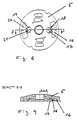
- Fig. 3
- einen Axialschnitt durch eine erfindungsgemäße Rollenzellenpumpe,
- Fig. 4
- einen Radialschnitt durch diese Rollenzellenpumpe,
- Fig. 5
- einen Radialschnitt durch eine Gleitschuhpumpe,
- Fig. 6
- einen Radialschnitt durch ein weiteres Ausführungsbeispiel,
- Fig. 7
- einen Teilschnitt durch das Gehäuse von Fig. 6,
- Fig. 8
- eine Draufsicht auf eine Stirnplatte,
- Fig. 9
- einen Schnitt durch diese Stirnplatte,
- Fig. 10
- eine Draufsicht auf ein anderes Ausführungsbeispiel einer Stirnplatte und
- Fig. 11
- einen Querschnitt durch diese Stirnplatte.
- 1
- Welle
- 2
- Gehäuse
- 3
- Deckel
- 4
- Steuerplatte
- 5
- Stirnplatte
- 6
- Kurvenring
- 7
- Rotor
- 8
- Schieber
- 9
- Saugniere
- 10
- Rolle
- 11
- Ausbuchtung
- 12
- Steg
- 13
- Gleitschuh
- 14
- Saugbereich
- 15
- Saugbereich
- 16
- Saugbereich
- 17
- Saugbereich
- 18
- Bohrungen
- 19
- Saugbereich
- 20
- Saugbereich
- 21
- Bohrungen
- 22
- Saugbereich
- 23
- Saugbereich
- 24
- Verbindungskanal
- 25
- Anlage
- 26
- Anlage
Claims (6)
- Verdrängerzellenpumpe zum Fördern eines Druckfluids aus einem Vorratsbehälter zu einem Verbraucher, insbesondere zu einer Hilfskraftlenkung eines Kraftfahrzeuges, bestehend aus:.dadurch gekennzeichnet, dass die Saugnieren derart ausgestaltet sind, dass ein Abheben der Schieber vom Kurvenring auch bei geringen Drehzahlen des Rotors verhindert wird.einem Gehäuse, das von einer Antriebswelle durchsetzt ist und in dem ein Saugkanal, ein Auslaßkanal, ein Stromregelventil und ein Strombegrenzungsventil angeordnet sind,einem Deckel, in dem eine gehäuseseitige Steuerplatte und eine deckelseitige Stirnplatte vorgesehen sind sowie ein Rotorsatz, der einen Kurvenring und einen mit der Antriebswelle verbundenen Rotor aufweist, der mit einer Vielzahl in Radialrichtung verschiebbar gelagerten Schiebern in Form von Flügeln, Rollen oder Gleitschuhen versehen ist, die bei Betrieb der Pumpe an der Innenwand des Kurvenringes entlang gleiten,wobei Gehäuse (2) und Stirnplatte (5) mit Saugnieren versehen sind, die mit dem Saugkanal in Verbindung stehen,
- Verdrängerzellenpumpe nach Anspruch 1, dadurch gekennzeichnet, dass die Saugniere (9) im Gehäuse (2) eine Ausbuchtung (11) aufweist, die eine Befüllung des Hinterrollenbereiches im Fall der Verwendung von Rollen (10) als Schieber ermöglicht.
- Verdrängerzellenpumpe nach Anspruch 2, dadurch gekennzeichnet, dass in der Ausbuchtung (11) in der Saugniere (9) im Gehäuse (2) ein Steg (12) angeordnet ist, der das Druckfluid kaskadenförmig in den Hinterrollenbereich lenkt.
- Verdrängerzellenpumpe nach Anspruch 1, dadurch gekennzeichnet, dass die Saugniere im Gehäuse (1) in zwei im wesentlichen S-förmige spiegelsymmetrisch zu einer die Antriebswelle (1) axial durchsetzenden gedachten Ebene (A) angeordnete Saugbereiche (14, 15) unterteilt ist, sodass der Hinterrollenbereich bevorzugt mit Druckfluid befüllt wird.
- Verdrängerzellenpumpe nach einem oder mehreren der vorhergehenden Ansprüche, dadurch gekennzeichnet, dass mehrere Saugnieren in der Stirnplatte (5) vorgesehen sind, wobei jede Saugniere aus zwei nebeneinander liegenden Saugbereichen (16, 17; 19, 2.0) besteht, die durch Bohrungen (18 bzw. 21) miteinander verbunden sind.
- Verdrängerzellenpumpe nach einem oder mehreren der vorhergehenden Ansprüche, dadurch gekennzeichnet, dass mehrere Saugnieren in der Stirnplatte (5) vorgesehen sind, wobei jede Saugniere aus zwei nebeneinander liegenden Saugbereichen (22, 23) besteht, die durch Verbindungskanäle (24) miteinander verbunden sind.
Applications Claiming Priority (2)
| Application Number | Priority Date | Filing Date | Title |
|---|---|---|---|
| DE2000115020 DE10015020A1 (de) | 2000-03-25 | 2000-03-25 | Verdrängerzellenpumpe |
| DE10015020 | 2000-03-25 |
Publications (2)
| Publication Number | Publication Date |
|---|---|
| EP1138947A2 true EP1138947A2 (de) | 2001-10-04 |
| EP1138947A3 EP1138947A3 (de) | 2002-10-30 |
Family
ID=7636452
Family Applications (1)
| Application Number | Title | Priority Date | Filing Date |
|---|---|---|---|
| EP01102011A Withdrawn EP1138947A3 (de) | 2000-03-25 | 2001-01-30 | Verdrängerzellenpumpe |
Country Status (2)
| Country | Link |
|---|---|
| EP (1) | EP1138947A3 (de) |
| DE (1) | DE10015020A1 (de) |
Cited By (2)
| Publication number | Priority date | Publication date | Assignee | Title |
|---|---|---|---|---|
| DE10233582B4 (de) * | 2002-07-24 | 2011-03-24 | Zf Lenksysteme Gmbh | Flügelzellenpumpe zur Förderung eines Fluids |
| DE102022200612A1 (de) | 2022-01-20 | 2023-07-20 | Zf Friedrichshafen Ag | Hydraulikgehäuse |
Citations (3)
| Publication number | Priority date | Publication date | Assignee | Title |
|---|---|---|---|---|
| DE2915809A1 (de) | 1978-05-01 | 1979-11-08 | Ford Werke Ag | Verdraengungspumpe, insbesondere fuer servoeinrichtungen in kraftfahrzeugen |
| DE8709476U1 (de) | 1987-07-09 | 1988-11-10 | Robert Bosch Gmbh, 7000 Stuttgart | Vorrichtung zum Fördern von Kraftstoff aus einem Vorratstank zur Brennkraftmaschine eines Kraftfahrzeuges |
| DE4438696A1 (de) | 1994-10-29 | 1996-05-02 | Zahnradfabrik Friedrichshafen | Flügelzellenpumpe |
Family Cites Families (9)
| Publication number | Priority date | Publication date | Assignee | Title |
|---|---|---|---|---|
| US3081706A (en) * | 1960-05-09 | 1963-03-19 | Thompson Ramo Wooldridge Inc | Slipper sealing means for a dual acting pump |
| US3200752A (en) * | 1963-05-16 | 1965-08-17 | Thompson Ramo Wooldridge Inc | Stack-up slipper pump with integral flow control valve |
| US3412685A (en) * | 1966-09-16 | 1968-11-26 | Eaton Yale & Towne | Pump |
| US3549288A (en) * | 1969-03-05 | 1970-12-22 | Ford Motor Co | Positive displacement slipper pump with flangeless drive shaft |
| US3865520A (en) * | 1971-09-08 | 1975-02-11 | Ingersoll Rand Co | Rotary motor with fluid pressure biased vane |
| GB1356906A (en) * | 1971-10-08 | 1974-06-19 | Ford Motor Co | Rotary positive displacement pump |
| US4072450A (en) * | 1976-01-12 | 1978-02-07 | Trw Inc. | Pump assembly |
| DE2655992A1 (de) * | 1976-12-10 | 1978-06-15 | Porsche Ag | Rollenzellenpumpe, insbesondere zur kraftstoffoerderung fuer brennkraftmaschinen |
| EP0851123B1 (de) * | 1996-12-23 | 2003-07-09 | LuK Fahrzeug-Hydraulik GmbH & Co. KG | Flügelzellenmaschine, insbesondere Flügelzellenpumpe |
-
2000
- 2000-03-25 DE DE2000115020 patent/DE10015020A1/de not_active Withdrawn
-
2001
- 2001-01-30 EP EP01102011A patent/EP1138947A3/de not_active Withdrawn
Patent Citations (3)
| Publication number | Priority date | Publication date | Assignee | Title |
|---|---|---|---|---|
| DE2915809A1 (de) | 1978-05-01 | 1979-11-08 | Ford Werke Ag | Verdraengungspumpe, insbesondere fuer servoeinrichtungen in kraftfahrzeugen |
| DE8709476U1 (de) | 1987-07-09 | 1988-11-10 | Robert Bosch Gmbh, 7000 Stuttgart | Vorrichtung zum Fördern von Kraftstoff aus einem Vorratstank zur Brennkraftmaschine eines Kraftfahrzeuges |
| DE4438696A1 (de) | 1994-10-29 | 1996-05-02 | Zahnradfabrik Friedrichshafen | Flügelzellenpumpe |
Cited By (2)
| Publication number | Priority date | Publication date | Assignee | Title |
|---|---|---|---|---|
| DE10233582B4 (de) * | 2002-07-24 | 2011-03-24 | Zf Lenksysteme Gmbh | Flügelzellenpumpe zur Förderung eines Fluids |
| DE102022200612A1 (de) | 2022-01-20 | 2023-07-20 | Zf Friedrichshafen Ag | Hydraulikgehäuse |
Also Published As
| Publication number | Publication date |
|---|---|
| DE10015020A1 (de) | 2001-09-27 |
| EP1138947A3 (de) | 2002-10-30 |
Similar Documents
| Publication | Publication Date | Title |
|---|---|---|
| DE4138313C2 (de) | Radialkolbenpumpe | |
| DE4200305C2 (de) | Regelbare Flügelzellenpumpe in kompakter Bauweise | |
| DE3307582C2 (de) | Ventilanordnung zur Steuerung eines aus Pumpe und Motor bestehenden hydrostatischen Antriebs oder Getriebes | |
| DE69303388T2 (de) | Anlage zur Energieumwandlung eines Fluidums mit veränderlicher Verdrängung | |
| DE2552256A1 (de) | Pumpe oder hydromotor | |
| DE3018711A1 (de) | Axialkolbenpumpe mit pumpeneinlaufkranz | |
| DE4030295C2 (de) | Pumpeneinheit mit Steuerventil | |
| DE10259894A1 (de) | Pumpe | |
| DE3803187A1 (de) | Rotationskolbenkompressor mit variabler foerderleistung | |
| DE3209640A1 (de) | Hydraulikpumpe | |
| DE102004021216B4 (de) | Hochdruck-Innenzahnradmaschine mit mehrfacher hydrostatischer Lagerung pro Hohlrad | |
| DE69009254T2 (de) | Hydraulische Kupplung. | |
| DE4143466C2 (de) | Steuerscheibe für Flügelzellenpumpe | |
| DE3102506A1 (de) | "kolbenpumpe mit geregelter foerderleistung" | |
| DE2504562C3 (de) | Hydrostatische Axialkolbenpumpe | |
| DE1812251C3 (de) | Flügelzellenpumpe | |
| DE19804374B4 (de) | Axialkolbenmaschine mit Mitteldrucköffnung | |
| DE4008522C2 (de) | ||
| DE4135904A1 (de) | Kolbenpumpe, insbesondere radialkolbenpumpe | |
| DE19539136B4 (de) | Flügelzellenverdichter | |
| EP1138947A2 (de) | Verdrängerzellenpumpe | |
| DE4109149C2 (de) | Steuerscheibe für Flügelzellenpumpe | |
| DE4438696A1 (de) | Flügelzellenpumpe | |
| DE3726800A1 (de) | Fluegelzellenmaschine | |
| EP1025363B1 (de) | Verdrängerpumpe |
Legal Events
| Date | Code | Title | Description |
|---|---|---|---|
| PUAI | Public reference made under article 153(3) epc to a published international application that has entered the european phase |
Free format text: ORIGINAL CODE: 0009012 |
|
| AK | Designated contracting states |
Kind code of ref document: A2 Designated state(s): AT BE CH CY DE DK ES FI FR GB GR IE IT LI LU MC NL PT SE TR |
|
| AX | Request for extension of the european patent |
Free format text: AL;LT;LV;MK;RO;SI |
|
| PUAL | Search report despatched |
Free format text: ORIGINAL CODE: 0009013 |
|
| AK | Designated contracting states |
Kind code of ref document: A3 Designated state(s): AT BE CH CY DE DK ES FI FR GB GR IE IT LI LU MC NL PT SE TR |
|
| AX | Request for extension of the european patent |
Free format text: AL;LT;LV;MK;RO;SI |
|
| AKX | Designation fees paid | ||
| REG | Reference to a national code |
Ref country code: DE Ref legal event code: 8566 |
|
| STAA | Information on the status of an ep patent application or granted ep patent |
Free format text: STATUS: THE APPLICATION IS DEEMED TO BE WITHDRAWN |
|
| 18D | Application deemed to be withdrawn |
Effective date: 20030503 |