EP1138912A1 - Online Optimierung eines Einspritzsystems mit piezolektrischen Elementen - Google Patents
Online Optimierung eines Einspritzsystems mit piezolektrischen Elementen Download PDFInfo
- Publication number
- EP1138912A1 EP1138912A1 EP00106993A EP00106993A EP1138912A1 EP 1138912 A1 EP1138912 A1 EP 1138912A1 EP 00106993 A EP00106993 A EP 00106993A EP 00106993 A EP00106993 A EP 00106993A EP 1138912 A1 EP1138912 A1 EP 1138912A1
- Authority
- EP
- European Patent Office
- Prior art keywords
- piezoelectric element
- voltage
- activation
- charging
- value
- Prior art date
- Legal status (The legal status is an assumption and is not a legal conclusion. Google has not performed a legal analysis and makes no representation as to the accuracy of the status listed.)
- Ceased
Links
- 238000002347 injection Methods 0.000 title claims abstract description 66
- 239000007924 injection Substances 0.000 title claims abstract description 66
- 238000005457 optimization Methods 0.000 title claims abstract description 28
- 239000000446 fuel Substances 0.000 claims abstract description 89
- 230000004913 activation Effects 0.000 claims abstract description 72
- 238000012937 correction Methods 0.000 claims abstract description 44
- 238000007599 discharging Methods 0.000 claims description 63
- 238000000034 method Methods 0.000 claims description 56
- 230000007613 environmental effect Effects 0.000 claims description 3
- 238000002485 combustion reaction Methods 0.000 abstract description 13
- 230000006870 function Effects 0.000 description 13
- 239000003990 capacitor Substances 0.000 description 9
- 230000007423 decrease Effects 0.000 description 8
- 238000006073 displacement reaction Methods 0.000 description 8
- 230000008859 change Effects 0.000 description 7
- 238000005259 measurement Methods 0.000 description 5
- 238000010586 diagram Methods 0.000 description 4
- 230000032683 aging Effects 0.000 description 3
- 230000008602 contraction Effects 0.000 description 3
- 230000001419 dependent effect Effects 0.000 description 3
- 230000003993 interaction Effects 0.000 description 3
- 230000008569 process Effects 0.000 description 3
- 230000009471 action Effects 0.000 description 2
- 230000003679 aging effect Effects 0.000 description 2
- 230000006399 behavior Effects 0.000 description 2
- 239000000470 constituent Substances 0.000 description 2
- 230000000694 effects Effects 0.000 description 2
- 230000003071 parasitic effect Effects 0.000 description 2
- 230000004044 response Effects 0.000 description 2
- 238000012546 transfer Methods 0.000 description 2
- 238000013459 approach Methods 0.000 description 1
- 230000005540 biological transmission Effects 0.000 description 1
- 230000015556 catabolic process Effects 0.000 description 1
- 230000008878 coupling Effects 0.000 description 1
- 238000010168 coupling process Methods 0.000 description 1
- 238000005859 coupling reaction Methods 0.000 description 1
- 230000003247 decreasing effect Effects 0.000 description 1
- 238000011161 development Methods 0.000 description 1
- 230000018109 developmental process Effects 0.000 description 1
- 239000012530 fluid Substances 0.000 description 1
- 239000000203 mixture Substances 0.000 description 1
- 238000000926 separation method Methods 0.000 description 1
- 230000011664 signaling Effects 0.000 description 1
Images


Classifications
-
- F—MECHANICAL ENGINEERING; LIGHTING; HEATING; WEAPONS; BLASTING
- F02—COMBUSTION ENGINES; HOT-GAS OR COMBUSTION-PRODUCT ENGINE PLANTS
- F02D—CONTROLLING COMBUSTION ENGINES
- F02D41/00—Electrical control of supply of combustible mixture or its constituents
- F02D41/20—Output circuits, e.g. for controlling currents in command coils
- F02D41/2096—Output circuits, e.g. for controlling currents in command coils for controlling piezoelectric injectors
-
- F—MECHANICAL ENGINEERING; LIGHTING; HEATING; WEAPONS; BLASTING
- F02—COMBUSTION ENGINES; HOT-GAS OR COMBUSTION-PRODUCT ENGINE PLANTS
- F02D—CONTROLLING COMBUSTION ENGINES
- F02D41/00—Electrical control of supply of combustible mixture or its constituents
- F02D41/24—Electrical control of supply of combustible mixture or its constituents characterised by the use of digital means
- F02D41/2406—Electrical control of supply of combustible mixture or its constituents characterised by the use of digital means using essentially read only memories
- F02D41/2425—Particular ways of programming the data
- F02D41/2429—Methods of calibrating or learning
- F02D41/2438—Active learning methods
-
- F—MECHANICAL ENGINEERING; LIGHTING; HEATING; WEAPONS; BLASTING
- F02—COMBUSTION ENGINES; HOT-GAS OR COMBUSTION-PRODUCT ENGINE PLANTS
- F02D—CONTROLLING COMBUSTION ENGINES
- F02D41/00—Electrical control of supply of combustible mixture or its constituents
- F02D41/24—Electrical control of supply of combustible mixture or its constituents characterised by the use of digital means
- F02D41/2406—Electrical control of supply of combustible mixture or its constituents characterised by the use of digital means using essentially read only memories
- F02D41/2425—Particular ways of programming the data
- F02D41/2429—Methods of calibrating or learning
- F02D41/2451—Methods of calibrating or learning characterised by what is learned or calibrated
- F02D41/2464—Characteristics of actuators
- F02D41/2467—Characteristics of actuators for injectors
-
- F—MECHANICAL ENGINEERING; LIGHTING; HEATING; WEAPONS; BLASTING
- F02—COMBUSTION ENGINES; HOT-GAS OR COMBUSTION-PRODUCT ENGINE PLANTS
- F02D—CONTROLLING COMBUSTION ENGINES
- F02D41/00—Electrical control of supply of combustible mixture or its constituents
- F02D41/008—Controlling each cylinder individually
Definitions
- the present invention relates to an apparatus as defined in the preamble of claim 1, and a method as defined in the preamble of claim 7, i.e. a method and an apparatus for charging a piezoelectric element.
- piezoelectric elements being considered in more detail are, in particular but not exclusively, piezoelectric elements used as actuators. Piezoelectric elements can be used for such purposes because, as is known, they possess the property of contracting or expanding as a function of a voltage applied thereto or occurring therein.
- piezoelectric elements as actuators proves to be advantageous, inter alia, in fuel injection nozzles for internal combustion engines.
- Piezoelectric elements are capacitative elements which, as already partially alluded to above, contract and expand in accordance with the particular charge state or the voltage occurring therein or applied thereto.
- expansion and contraction of piezoelectric elements is used to control valves that manipulate the linear strokes of injection needles.
- German patent applications DE 197 42 073 A1 and DE 197 29 844 A1 which are described below and are incorporated herein by reference in their entirety, disclose piezoelectric elements with double acting, double seat valves for controlling injection needles in a fuel injection system.
- a fuel injection nozzle for example, implemented as a double acting, double seat valve to control the linear stroke of a needle for fuel injection into a cylinder of an internal combustion engine
- the amount of fuel injected into a corresponding cylinder is a function of the time the valve is open, and in the case of the use of a piezoelectric element, the activation voltage applied to the piezoelectric element. If the valve plug of the control valve is located in one of the two seats of the double seat valve, the nozzle needle remains or becomes closed. If the valve plug is in an intermediate position between the seats, then the nozzle needle remains or becomes open.
- a goal is to achieve a desired fuel injection volume with high accuracy, especially at small injection volumes, for example during pre-injection.
- the piezoelectric element is to be expanded or contracted by the effect of an activation voltage applied to the piezoelectric element, so that a corresponding controlled valve plug is positioned midway between the two seats of the double acting control valve to position the corresponding injection needle for maximum fuel flow during a set time period. It has proven to be difficult to determine and apply an activation voltage suitable for all injection elements and the whole lifetime of the injection system with sufficient precision such that, for example, a corresponding valve plug is accurately positioned for maximum fuel flow.
- an activation voltage level for a piezoelectric element is set with sufficient precision to, for example, accurately position a valve plug for maximum fuel flow.
- the particular piezoelectric element can be one of several piezoelectric elements used as actuators in a system such as, for example, a fuel injection system.
- the amount of expansion or contraction of piezoelectric elements is influenced by operating characteristics of each particular piezoelectric element, and can vary from sample-to-sample and/or with the ages of the piezoelectric elements.
- the amount of displacement of a particular actuator implemented as a piezoelectric element, in response to application of a particular voltage can vary as a function of, for example, the operating characteristics of the particular piezoelectric element, and/or the age of the actuator.
- the result is that actuators behave differently when charged to the same voltage, and their operation can vary over time.
- the activation voltage level for a piezoelectric element is influenced by operating characteristics, and changes in the operating characteristics with age, of the particular piezoelectric element. In terms of fuel injection and injection profile, this generally infers a deviation from optimum system operation. Furthermore, sample-to-sample deviation and aging effects of the hydraulic components themselves influence the behavior of the whole injection system, too. Prior to the present invention, these effects could be overcome only by designing injection equipment so robustly that variations due to particular operating characteristics and age of actuators have little or no repercussions in system operation.
- control valves can be controlled with sufficient accuracy independently of sample-to-sample variations of operating characteristics of the actuators, or changes in operating characteristics with age.
- the activation voltage applied to a piezoelectric element at any particular time will be appropriate relative to the operating characteristics of the particular piezoelectric element at the time of application of the voltage. In this manner, a desired injection volume can be achieved with sufficient accuracy even if the injection volume is small or the injection profile complex.
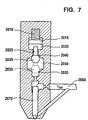
- Fig. 7 is a schematic representation of a fuel injection system using a piezoelectric element 2010 as an actuator.
- the piezoelectric element 2010 is electrically energized to expand and contract in response to a given activation voltage.
- the piezoelectric element 2010 is coupled to a piston 2015.
- the piezoelectric element 2010 causes the piston 2015 to protrude into a hydraulic adapter 2020 which contains a hydraulic fluid, for example fuel.
- a double acting control valve 2025 is hydraulically pushed away from hydraulic adapter 2020 and the valve plug 2035 is extended away from a first closed position 2040.
- double acting control valve 2025 and hollow bore 2050 is often referred to as double acting, double seat valve for the reason that when piezoelectric element 2010 is in an unexcited state, the double acting control valve 2025 rests in its first closed position 2040. On the other hand, when the piezoelectric element 2010 is fully extended, it rests in its second closed position 2030.
- the later position of valve plug 2035 is schematically represented with ghost lines in Fig. 7.
- the fuel injection system comprises an injection needle 2070 allowing for injection of fuel from a pressurized fuel supply line 2060 into the cylinder (not shown).
- the double acting control valve 2025 rests respectively in its first closed position 2040 or in its second closed position 2030. In either case, the hydraulic rail pressure maintains injection needle 2070 at a closed position. Thus, the fuel mixture does not enter into the cylinder (not shown).
- the piezoelectric element 2010 is excited such that double acting control valve 2025 is in the so-called mid-position with respect to the hollow bore 2050, then there is a pressure drop in the pressurized fuel supply line 2060. This pressure drop results in a pressure differential in the pressurized fuel supply line 2060 between the top and the bottom of the injection needle 2070 so that the injection needle 2070 is lifted allowing for fuel injection into the cylinder (not shown).
- Fig. 1 shows a graph depicting the relationship between activation voltage U and injected fuel volume Q during a preselected fixed time period, for an exemplary fuel injection system using piezoelectric elements acting upon double seat control valves.
- the y-axis represents volume of fuel injected into a cylinder chamber during the preselected fixed period of time.
- the x-axis represents the activation voltage applied to or stored in the corresponding piezoelectric element, used to displace a valve plug of the double acting control valve.
- the activation voltage is zero, and the valve plug is seated in a first closed position to prevent the flow of fuel during the preselected fixed period of time.
- the represented values of the activation voltage cause the displacement of the valve plug away from the first seat and towards the second closed position, in a manner that results in a greater volume of injected fuel for the fixed time period, as the activation voltage approaches U opt , up to the value for volume indicted on the y-axis by Q e,max .
- the point Q e,max corresponding to the greatest volume for the injected fuel during the fixed period of time, represents the value of the activation voltage for application to or charging of the piezoelectric element, that results in an optimal displacement of the valve plug between the first and second valve seats.
- the volume of fuel injected during the fixed period of time decrease until it reaches zero. This represents displacement of the valve plug from the optimal point and toward the second seat of the double acting control valve until the valve plug is seated against the second closed position.
- the graph of Fig. 1 illustrates that a maximum volume of fuel injection occurs when the activation voltage causes the piezoelectric element to displace the valve plug to the optimal point.
- the present invention teaches that the value for U opt at any given time for a particular piezoelectric element is influenced by the operating characteristics of the particular piezoelectric element at that time. That is, the amount of displacement caused by the piezoelectric element for a certain activation voltage varies as a function of the operating characteristics of the particular piezoelectric element. Accordingly, in order to achieve a maximum volume of fuel injection, Q e,max , during a given fixed period of time, the activation voltage applied to or occurring in the piezoelectric element should be set to a value relevant to current operating characteristics of the particular piezoelectric element, to achieve U opt .
- Fig. 2 shows a double graph representing a schematic profile of an exemplary control valve stroke, to illustrate the double acting control valve operation discussed above.
- the x-axis represents time
- the y-axis represents displacement of the valve plug (valve lift).
- the x-axis once again represents time
- the y-axis represents a nozzle needle lift to provide fuel flow, resulting from the valve lift of the upper graph.
- the upper and lower graphs are aligned with one another to coincide in time, as represented by the respective x-axises.
- the piezoelectric element is charged resulting in an expansion of the piezoelectric element, as will be described in greater detail, and causing the corresponding valve plug to move from the first seat to the second seat for a pre-injection stroke, as shown in the upper graph of Fig. 2.
- the lower graph of Fig. 2 shows a small injection of fuel that occurs as the valve plug moves between the two seats of the double acting control valve, opening and closing the valve as the plug moves between the seats.
- the charging of the piezoelectric element can be done in two steps: the first one is to charge it to a certain voltage and cause the valve to open, and the second one is to charge it further and cause the control valve to close again at the second closed position. Between steps, in general, there can be a certain time delay.
- a discharging operation is then performed, as will be explained in greater detail below, to reduce the charge within the piezoelectric element so that it contracts, as will also be described in greater detail, causing the valve plug to move away from the second closed position, and hold at a midway point between the two seats.
- the activation voltage within the piezoelectric element is to reach a value that equals U opt to correspond to an optimal point of the valve lift, and thereby obtain a maximum fuel flow, Q e,max , during the period of time allocated to a main injection.
- the upper and lower graphs of Fig. 2 show the holding of the valve lift at a midway point, resulting in a main fuel injection.
- the piezoelectric element is discharged to an activation voltage of zero, resulting in further contraction of the piezoelectric element, to cause the valve plug to move away from the optimal position, towards the first seat, closing the valve and stopping fuel flow, as shown in the upper and lower graphs of Fig. 2.
- the valve plug will once again be in a position to repeat another pre-injection, main injection cycle, as just described above, for example.
- any other injection cycle can be performed.
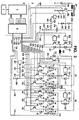
- Fig. 3 provides a block diagram of an exemplary embodiment of an arrangement in which the present invention may be implemented.
- Fig. 3 there is a detailed area A and a non-detailed area B, the separation of which is indicated by a dashed line c.
- the detailed area A comprises a circuit for charging and discharging piezoelectric elements 10, 20, 30, 40, 50 and 60.
- these piezoelectric elements 10, 20, 30, 40, 50 and 60 are actuators in fuel injection nozzles (in particular in so-called common rail injectors) of an internal combustion engine.
- Piezoelectric elements can be used for such purposes because, as is known, and as discussed above, they possess the property of contracting or expanding as a function of a voltage applied thereto or occurring therein.
- the reason to take six piezoelectric elements 10, 20, 30, 40, 50 and 60 in the embodiment described is to independently control six cylinders within a combustion engine; hence, any other number of piezoelectric elements might match any other purpose.
- the non-detailed area B comprises a control unit D and a activation IC E by both of which the elements within the detailed area A are controlled, as well as a measuring system F for measuring system operating characteristics such as, for example, fuel pressure and rotational speed (rpm) of the internal combustion engine for input to and use by the control unit D, according to the present invention, as will be described in detail below.
- the control unit D and activation IC E are programmed to control activation voltages for piezoelectric elements as a function of operating characteristics of the each particular piezoelectric element.
- the circuit within the detailed area A comprises six piezoelectric elements 10, 20, 30, 40, 50 and 60.
- the piezoelectric elements 10, 20, 30, 40, 50 and 60 are distributed into a first group G1 and a second group G2, each comprising three piezoelectric elements (i.e. piezoelectric elements 10, 20 and 30 in the first group G1 resp. 40, 50 and 60 in the second group G2).
- Groups G1 and G2 are constituents of circuit parts connected in parallel with one another.
- Group selector switches 310, 320 can be used to establish which of the groups G1, G2 of piezoelectric elements 10, 20 and 30 resp. 40, 50 and 60 will be discharged in each case by a common charging and discharging apparatus (however, the group selector switches 310, 320 are meaningless for charging procedures, as is explained in further detail below).
- the group selector switches 310, 320 are arranged between a coil 240 and the respective groups G1 and G2 (the coil-side terminals thereof) and are implemented as transistors.
- Side drivers 311, 321 are implemented which transform control signals received from the activation IC E into voltages which are eligible for closing and opening the switches as required.
- Diodes 315 and 325 are provided in parallel with the group selector switches 310, 320. If the group selector switches 310, 320 are implemented as MOSFETs or IGBTs, for example, these group selector diodes 315 and 325 can be constituted by the parasitic diodes themselves. The diodes 315, 325 bypass the group selector switches 310, 320 during charging procedures. Hence, the functionality of the group selector switches 310, 320 is reduced to select a group G1, G2 of piezoelectric elements 10, 20 and 30, resp. 40, 50 and 60 for a discharging procedure only.
- each piezo branch comprises a series circuit made up of a first parallel circuit comprising a piezoelectric element 10, 20, 30, 40, 50 resp. 60 and a resistor 13, 23, 33, 43, 53 resp. 63 (referred to as branch resistors) and a second parallel circuit made up of a selector switch implemented as a transistor 11, 21, 31, 41, 51 resp. 61 (referred to as branch selector switches) and a diode 12, 22, 32, 42, 52 resp. 62 (referred to as branch diodes).
- the branch resistors 13, 23, 33, 43, 53 resp. 63 cause each corresponding piezoelectric element 10, 20, 30, 40, 50 resp. 60 during and after a charging procedure to continuously discharge themselves, since they connect both terminals of each capacitive piezoelectric element 10, 20, 30, 40, 50, resp. 60 one to another.
- the branch resistors 13, 23, 33, 43, 53 resp. 63 are sufficiently large to make this procedure slow compared to the controlled charging and discharging procedures as described below.
- the branch selector switch/branch diode pairs in the individual piezo branches 110, 120, 130, 140, 150 resp. 160 i.e. selector switch 11 and diode 12 in piezo branch 110, selector switch 21 and diode 22 in piezo branch 120, and so on, can be implemented using electronic switches (i.e. transistors) with parasitic diodes, for example MOSFETs or IGBTs (as stated above for the group selector switch/diode pairs 310 and 315 resp. 320 and 325).
- the branch selector switches 11, 21, 31, 41, 51 resp. 61 can be used to establish which of the piezoelectric elements 10, 20, 30, 40, 50 or 60 will be charged in each case by a common charging and discharging apparatus: in each case, the piezoelectric elements 10, 20, 30, 40, 50 or 60 that are charged are all those whose branch selector switches 11, 21, 31, 41, 51 or 61 are closed during the charging procedure which is described below. Usually, at any time only one of the branch selector switches is closed.
- the branch diodes 12, 22, 32, 42, 52 and 62 serve for bypassing the branch selector switches 11, 21, 31, 41, 51 resp. 61 during discharging procedures.
- any individual piezoelectric element can be selected, whereas for discharging procedures either the first group G1 or the second group G2 of piezoelectric elements 10, 20 and 30 resp. 40, 50 and 60 or both have to be selected.
- the branch selector piezo terminals 15, 25, 35, 45, 55 resp. 65 may be connected to ground either through the branch selector switches 11, 21, 31, 41, 51 resp. 61 or through the corresponding diodes 12, 22, 32, 42, 52 resp. 62 and in both cases additionally through resistor 300.
- resistor 300 The purpose of resistor 300 is to measure the currents that flow during charging and discharging of the piezoelectric elements 10, 20, 30, 40, 50 and 60 between the branch selector piezo terminals 15, 25, 35, 45, 55 resp. 65 and the ground. A knowledge of these currents allows a controlled charging and discharging of the piezoelectric elements 10, 20, 30, 40, 50 and 60. In particular, by closing and opening charging switch 220 and discharging switch 230 in a manner dependent on the magnitude of the currents, it is possible to set the charging current and discharging current to predefined average values and/or to keep them from exceeding or falling below predefined maximum and/or minimum values as is explained in further detail below.
- the measurement itself further requires a voltage source 621 which supplies a voltage of 5 V DC, for example, and a voltage divider implemented as two resistors 622 and 623.
- a voltage source 621 which supplies a voltage of 5 V DC, for example
- a voltage divider implemented as two resistors 622 and 623.
- each piezoelectric element 10, 20, 30, 40, 50 and 60 i.e. the group selector piezo terminal 14, 24, 34, 44, 54 resp. 64
- the other terminal of each piezoelectric element 10, 20, 30, 40, 50 and 60 may be connected to the plus pole of a voltage source via the group selector switch 310 resp. 320 or via the group selector diode 315 resp. 325 as well as via a coil 240 and a parallel circuit made up of a charging switch 220 and a charging diode 221, and alternatively or additionally connected to ground via the group selector switch 310 resp. 320 or via diode 315 resp. 325 as well as via the coil 240 and a parallel circuit made up of a discharging switch 230 or a discharging diode 231.
- Charging switch 220 and discharging switch 230 are implemented as transistors, for example, which are controlled via side drivers 222 and 232, respectively.
- the voltage source comprises an element having capacitive properties which, in the example being considered, is the (buffer) capacitor 210.
- Capacitor 210 is charged by a battery 200 (for example a motor vehicle battery) and a DC voltage converter 201 downstream therefrom.
- DC voltage converter 201 converts the battery voltage (for example, 12 V) into substantially any other DC voltage (for example 250 V), and charges capacitor 210 to that voltage.
- DC voltage converter 201 is controlled by means of transistor switch 202 and resistor 203 which is utilized for current measurements taken from a measuring point 630.
- a further current measurement at a measuring point 650 is allowed by activation IC E as well as by resistors 651, 652 and 653 and a 5 V DC voltage, for example, source 654; moreover, a voltage measurement at a measuring point 640 is allowed by activation IC E as well as by voltage dividing resistors 641 and 642.
- a resistor 330 (referred to as total discharging resistor), a stop switch implemented as a transistor 331 (referred to as stop switch), and a diode 332 (referred to as total discharging diode) serve to discharge the piezoelectric elements 10, 20, 30, 40, 50 and 60 (if they happen to be not discharged by the "normal" discharging operation as described further below).
- Stop switch 331 is preferably closed after “normal” discharging procedures (cycled discharging via discharge switch 230). It thereby connects piezoelectric elements 10, 20, 30, 40, 50 and 60 to ground through resistors 330 and 300, and thus removes any residual charges that might remain in piezoelectric elements 10, 20, 30, 40, 50 and 60.
- the total discharging diode 332 prevents negative voltages from occurring at the piezoelectric elements 10, 20, 30, 40, 50 and 60, which might in some circumstances be damaged thereby.
- Charging and discharging of all the piezoelectric elements 10, 20, 30, 40, 50 and 60 or any particular one is accomplished by way of a single charging and discharging apparatus (common to all the groups and their piezoelectric elements).
- the common charging and discharging apparatus comprises battery 200, DC voltage converter 201, capacitor 210, charging switch 220 and discharging switch 230, charging diode 221 and discharging diode 231 and coil 240.
- each piezoelectric element works the same way and is explained in the following while referring to the first piezoelectric element 10 only.
- FIGS. 4A through 4D illustrate the charging of piezoelectric element 10
- FIGS. 4C and 4D the discharging of piezoelectric element 10.
- the selection of one or more particular piezoelectric elements 10, 20, 30, 40, 50 or 60 to be charged or discharged, the charging procedure as described in the following as well as the discharging procedure are driven by activation IC E and control unit D by means of opening or closing one or more of the above introduced switches 11, 21, 31, 41, 51, 61; 310, 320; 220, 230 and 331.
- activation IC E and control unit D The interactions between the elements within the detailed area A on the one hand and activation IC E and control unit D on the other hand are described in detail further below.
- any particular piezoelectric element 10, 20, 30, 40, 50 or 60 which is to be charged has to be selected.
- the branch selector switch 11 of the first branch 110 is closed, whereas all other branch selector switches 21, 31, 41, 51 and 61 remain opened.
- the charging procedure requires a positive potential difference between capacitor 210 and the group selector piezo terminal 14 of the first piezoelectric element 10.
- charging switch 220 and discharging switch 230 are open no charging or discharging of piezoelectric element 10 occurs: In this state, the circuit shown in Fig. 3 is in a steady-state condition, i.e. piezoelectric element 10 retains its charge state in substantially unchanged fashion, and no currents flow.
- charging switch 220 In order to charge the first piezoelectric element 10, charging switch 220 is closed. Theoretically, the first piezoelectric element 10 could become charged just by doing so. However, this would produce large currents which might damage the elements involved. Therefore, the occurring currents are measured at measuring point 620 and switch 220 is opened again as soon as the detected currents exceed a certain limit. Hence, in order to achieve any desired charge on the first piezoelectric element 10, charging switch 220 is repeatedly closed and opened whereas discharging switch 230 remains open.
- a closed circuit comprising a series circuit made up of piezoelectric element 10, capacitor 210, and coil 240 is formed, in which a current i LE (t) flows as indicated by arrows in Fig. 4A.
- a current i LE (t) flows as indicated by arrows in Fig. 4A.
- a closed circuit comprising a series circuit made up of piezoelectric element 10, charging diode 221, and coil 240 is formed, in which a current i LA (t) flows as indicated by arrows in Fig. 4B.
- the result of this current flow is that energy stored in coil 240 flows into piezoelectric element 10.
- the voltage occurring in the latter, and its external dimensions increase.
- charging switch 220 is once again closed and opened again, so that the processes described above are repeated.
- the energy stored in piezoelectric element 10 increases (the energy already stored in the piezoelectric element 10 and the newly delivered energy are added together), and the voltage occurring at the piezoelectric element 10, and its external dimensions, accordingly increase.
- charging switch 220 has closed and opened a predefined number of times, and/or once piezoelectric element 10 has reached the desired charge state, charging of the piezoelectric element is terminated by leaving charging switch 220 open.
- the piezoelectric elements 10, 20, 30, 40, 50 and 60 are discharged in groups (G1 and/or G2) as follows:
- the group selector switch(es) 310 and/or 320 of the group or groups G1 and/or G2 the piezoelectric elements of which are to be discharged are closed (the branch selector switches 11, 21, 31, 41, 51, 61 do not affect the selection of piezoelectric elements 10, 20, 30, 40, 50, 60 for the discharging procedure, since in this case they are bypassed by the branch diodes 12, 22, 32, 42, 52 and 62).
- the first group selector switch 310 is closed.
- a closed circuit comprising a series circuit made up of piezoelectric element 10 and coil 240 is formed, in which a current i EE (t) flows as indicated by arrows in Figure 4C.
- a current i EE (t) flows as indicated by arrows in Figure 4C.
- the result of this current flow is that the energy (a portion thereof) stored in the piezoelectric element is transported into coil 240.
- the voltage occurring at the piezoelectric element 10 decrease.
- a closed circuit comprising a series circuit made up of piezoelectric element 10, capacitor 210, discharging diode 231, and coil 240 is formed, in which a current i EA (t) flows as indicated by arrows in Figure 4D.
- a current i EA (t) flows as indicated by arrows in Figure 4D.
- discharging switch 230 is once again closed and opened again, so that the processes described above are repeated.
- the energy stored in piezoelectric element 10 decreases further, and the voltage occurring at the piezoelectric element, and its external dimensions, also accordingly decrease.
- discharging switch 230 Once discharging switch 230 has closed and opened a predefined number of times, and/or once the piezoelectric element has reached the desired discharge state, discharging of the piezoelectric element 10 is terminated by leaving discharging switch 230 open.
- activation IC E and control unit D on the one hand and the elements within the detailed area A on the other hand is performed by control signals sent from activation IC E to elements within the detailed area A via branch selector control lines 410, 420, 430, 440, 450, 460, group selector control lines 510, 520, stop switch control line 530, charging switch control line 540 and discharging switch control line 550 and control line 560.
- sensor signals obtained on measuring points 600, 610, 620, 630, 640, 650 within the detailed area A which are transmitted to activation IC E via sensor lines 700, 710, 720, 730, 740, 750.
- the control lines are used to apply or not to apply voltages to the transistor bases in order to select piezoelectric elements 10, 20, 30, 40, 50 or 60, to perform charging or discharging procedures of single or several piezoelectric elements 10, 20, 30, 40, 50, 60 by means of opening and closing the corresponding switches as described above.
- the sensor signals are particularly used to determine the resulting voltage of the piezoelectric elements 10, 20 and 30, resp. 40, 50 and 60 from measuring points 600 resp. 610 and the charging and discharging currents from measuring point 620.
- the control unit D and the activation IC E are used to combine both kinds of signals in order to perform an interaction of both as will be described in detail now while referring to FIGs. 3 and 5.
- control unit D and the activation IC E are connected to each other by means of a parallel bus 840 and additionally by means of a serial bus 850.
- the parallel bus 840 is particularly used for fast transmission of control signals from control unit D to the activation IC E, whereas the serial bus 850 is used for slower data transfer.
- the activation IC E comprises: a logic circuit 800, RAM memory 810, digital to analog converter system 820 and comparator system 830. Furthermore, it is indicated that the fast parallel bus 840 (used for control signals) is connected to the logic circuit 800 of the activation IC E, whereas the slower serial bus 850 is connected to the RAM memory 810.
- the logic circuit 800 is connected to the RAM memory 810, to the comparator system 830 and to the signal lines 410, 420, 430, 440, 450 and 460; 510 and 520; 530; 540, 550 and 560.
- the RAM memory 810 is connected to the logic circuit 800 as well as to the digital to analog converter system 820.
- the digital to analog converter system 820 is further connected to the comparator system 830.
- the comparator system 830 is further connected to the sensor lines 700 and 710; 720; 730, 740 and 750 and -as already mentioned- to the logic circuit 800.
- a particular piezoelectric element 10, 20, 30, 40, 50 or 60 is determined which is to be charged to a certain target voltage.
- the target voltage can be, for example, the value for U opt used in a main injection, as described above with respect to Fig. 1.
- a code corresponding to the particular piezoelectric element 10, 20, 30, 40, 50 or 60 which is to be selected and the address of the desired voltage within the RAM memory 810 is transmitted to the logic circuit 800 via the parallel bus 840.
- a strobe signal is sent to the logic circuit 800 via the parallel bus 840 which gives the start signal for the charging procedure.
- the start signal firstly causes the logic circuit 800 to pick up the digital value of the target voltage from the RAM memory 810 and to put it on the digital to analog converter system 820 whereby at one analog exit of the converters 820 the desired voltage occurs. Moreover, said analog exit (not shown) is connected to the comparator system 830.
- the logic circuit 800 selects either measuring point 600 (for any of the piezoelectric elements 10, 20 or 30 of the first group G1) or measuring point 610 (for any of the piezoelectric elements 40, 50 or 60 of the second group G2) to the comparator system 830. Resulting thereof, the target voltage and the present voltage at the selected piezoelectric element 10, 20, 30, 40, 50 or 60 are compared by the comparator system 830. The results of the comparison, i.e. the differences between the target voltage and the present voltage, are transmitted to the logic circuit 800. Thereby, the logic circuit 800 can stop the procedure as soon as the target voltage and the present voltage are equal to one another.
- the logic circuit 800 applies a control signal to the branch selector switch 11, 21, 31, 41, 51 or 61 which corresponds to any selected piezoelectric element 10, 20, 30, 40, 50 or 60 so that the switch becomes closed (all branch selector switches 11, 21, 31, 41, 51 and 61 are considered to be in an open state before the onset of the charging procedure within the example described). Then, the logic circuit 800 applies a control signal to the charging switch 220 so that the switch becomes closed. Furthermore, the logic circuit 800 starts (or continues) measuring any currents occurring on measuring point 620. Hereto, the measured currents are compared to any predefined maximum value by the comparator system 830. As soon as the predefined maximum value is achieved by the detected currents, the logic circuit 800 causes the charging switch 220 to open again.
- the logic circuit 800 causes the charging switch 220 to close again and the procedure starts once again.
- the closing and opening of the charging switch 220 is repeated as long as the detected voltage at measuring point 600 or 610 is below the target voltage. As soon as the target voltage is achieved, the logic circuit stops the continuation of the procedure.
- the discharging procedure takes place in a corresponding way: Now the selection of the piezoelectric element 10, 20, 30, 40, 50 or 60 is obtained by means of the group selector switches 310 resp. 320, the discharging switch 230 instead of the charging switch 220 is opened and closed and a predefined minimum target voltage is to be achieved.
- the timing of the charging and discharging operations and the holding of voltage levels in the piezoelectric elements 10, 20, 30, 40, 50 or 60, as for example, the time of a main injection, can be determined and accomplished according to the parameters of a valve stroke, according to a valve stroke, as shown, for example, in Fig. 2.
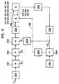
- Fig. 6 shows a configuration for controlling a combustion engine 2505.
- This configuration comprises a basic voltage calculation unit 2500 which calculates a basic voltage to be applied to the piezoelectric elements 10, 20, 30, 40, 50, and 60, of the circuit included in the detailed area A of Fig. 6; the detailed area A is also shown in Fig. 3.
- the basic voltage calculation unit 2500 calculates a basic voltage dependent on the pressure P rail in the fuel supply line of the fuel injection system.
- the basic voltage is corrected via a first correction block 2501 using a temperature correction value K T .
- the output from the first correction block 2501 is a corrected basic voltage.
- This corrected basic voltage is preferably corrected by a second or subsequent correction block 2502 using an aging correction value K A .
- the first and second correction blocks 2501 and 2502 are preferably multipliers, i.e., the basic voltage is multiplied by the temperature correction value K T and the output enters the second or subsequent correction block 2502 and is multiplied by the aging correction value K A .
- the output of the second or subsequent correction block 2502 is preferably further corrected via a third or subsequent correction block 2503 using an online correction value K O .
- the third or subsequent correction block 2503 is preferably implemented as an adder, i.e., the online correction value K O is preferably added to the output of the second or subsequent correction block 2502.
- the output of the third or subsequent correction block 2503 is preferably fed through a voltage and voltage gradient controller 2504.
- the basic voltage calculation unit 2500, the correction blocks 2501, 2502, and 2503, and the voltage and voltage controller are software modules implemented in control unit D in Fig. 3.
- the voltage and voltage gradient controller 2504 is connected to activation IC E via serial bus 850.
- the activation IC E and the detailed area A are connected to each by sensor lines 700, 710, 720, 730, 740, and 750 and signal lines 410, 420, 430, 440, 450, 460, and 510, 520, 530, 540, 550, and 560.
- the fuel injection into the combustion engine 2505 is controlled via the piezoelectric elements 10, 20, 30, 40, 50, and 60, of the circuit within the detailed area A shown in Fig. 3.
- the rotational speed of the combustion engine 2505 is measured and fed into a fuel correction unit 2506.
- the fuel correction unit 2506 comprises a frequency analyzer which evaluates the frequency of the rotational speed.
- the fuel correction unit 2506 calculates a fuel correction value ⁇ Q E upon this frequency analysis for each individual cylinder of the combustion engine 2505.
- the configuration shown in Fig. 6 also comprises a fuel volume calculation unit 2507 calculating a desired fuel volume Q E .
- the desired fuel volume is added to the fuel volume correction value ⁇ Q E via an adder 2508.
- the sum of the desired fuel volume Q E and the fuel volume correction value ⁇ Q E is fed into a fuel metering unit 2509.
- the fuel metering unit calculates the time a voltage has to be applied to the piezoelectric elements 10, 20, 30, 40, 50 and 60, to inject fuel into the combustion engine 2505.
- the fuel correction unit 2506, the adder 2508, the fuel volume calculation unit 2507 and the fuel metering unit are implemented in the control unit D. Time signals to signaling when a voltage has to be applied to the piezoelectric elements 10, 20 ,30, 40, 50 and 60, to inject fuel into the combustion engine 2505 are transferred to activation IC E via parallel bus 840.
- the online correction value K O is calculated by an online optimization unit 2510.
- the online optimization unit 2510 calculates the online correction value K O based upon the fuel correction value ⁇ Q E calculated by the fuel correction unit 2506.
- the volume of injected fuel is a function of both the time the valve is opened as calculated by the metering unit 2509, and the activation voltage applied to the piezoelectric element during the time period.
- An objective in operating the fuel injection system is to achieve an activation voltage value of U opt shown in Fig. 1 for the period of main injection.
- Another objective is to optimize the activation voltage when charging the piezoelectric element so as to move the control valve from the first seat to the midway position.
- the voltage gradient has to be optimized, since voltage gradients also have a relationship to fuel volume similar to the relationship between voltage and fuel volume.
- the values stored in the RAM memory 810 include the voltages that are used in charging and/or discharging procedures as well as parameters influencing the voltage gradient.
- the U opt values can change as a function of operating characteristics of the fuel injection system, such as, for example, fuel pressure. That is, the amount of displacement caused by the piezoelectric element for a certain activation voltage varies as a function of the fuel pressure. Accordingly, in order to achieve a maximum volume of fuel injection, Q e,max during a given fixed period of time, the activation voltage applied to or occurring in the piezoelectric element should be set to a value relevant to a current fuel pressure, to achieve U opt .
- the U opt can especially change from sample to sample of the injection system as a function of operating characteristics of the injector system such as, for example, the injector and the piezo element and their age.
- an online optimization unit 2510 comprises, for example, a software module in the control unit D having an input coupled to the output of the fuel correction unit 2506 to receive a ⁇ Q Ei value for each cylinder.
- the online optimization unit 2510 is based upon the recognition that the ⁇ Q Ei value for each cylinder can be influenced by operating characteristics of the particular piezoelectric element corresponding to the cylinder or changes over time of the operating characteristics for that actuator.
- the online optimization unit 2510 selects an incremental change in the voltage U applied to the corresponding actuator as an optimization step, and inputs the selection to the third correction block 2503.
- the online optimization unit 2510 continues to monitor the value of ⁇ Q Ei after U is changed.
- the online optimization unit 2510 will then select an additional incremental change in the voltage U in the same direction, and so on, if the value of ⁇ Q Ei continues to decrease. This procedure continues until the value of ⁇ Q Ei is minimized. If the value of ⁇ Q Ei increases after an incremental change, then the change direction was incorrect, and the optimization step is discarded. The online optimization unit 2510 can then begin incremental changes in the opposite direction, for example, a subtraction value to be summed with the current value of U.
- the optimization unit 2510 adjusts the value for U opt for each particular piezoelectric element 10, 20, 30, 40, 50 or 60, to accommodate differences in the operating characteristics between the piezoelectric elements 10, 20, 30, 40, 50 or 60, changes in the operating characteristics for any particular piezoelectric element with age, as well as differences in the behaviors of the hydraulic injection elements.
- the optimization unit 2510 can be enabled or disabled, for example by an activation enabling unit (not shown in Fig. 6). Depending on some environmental data, for example the engine speed r.p.m., the rail pressure, the temperature and so on, the activation enabling unit can enable or disable the optimization unit 2510.
- the optimization can be performed in predefined time intervals, too.
- the result of the optimization can be a correction value being constant for all operating points.
- the optimization process can be performed for several cylinders at the same time.
- optimization makes certain that the aging and operating characteristics of each particular piezoelectric element is compensated for in a determination of an activation voltage level.
- the method is not limited to double-switching valves but can be performed for any kind of injection system with piezoelectric elements used as actuators.
Priority Applications (3)
| Application Number | Priority Date | Filing Date | Title |
|---|---|---|---|
| EP00106993A EP1138912A1 (de) | 2000-04-01 | 2000-04-01 | Online Optimierung eines Einspritzsystems mit piezolektrischen Elementen |
| US09/824,081 US6691682B2 (en) | 2000-04-01 | 2001-04-02 | Online optimization of injection systems having piezoelectric elements |
| JP2001103958A JP2001349238A (ja) | 2000-04-01 | 2001-04-02 | 圧電素子を有する燃料噴射システムおよび圧電素子を有する燃料噴射システムを操作する方法 |
Applications Claiming Priority (1)
| Application Number | Priority Date | Filing Date | Title |
|---|---|---|---|
| EP00106993A EP1138912A1 (de) | 2000-04-01 | 2000-04-01 | Online Optimierung eines Einspritzsystems mit piezolektrischen Elementen |
Publications (1)
| Publication Number | Publication Date |
|---|---|
| EP1138912A1 true EP1138912A1 (de) | 2001-10-04 |
Family
ID=8168333
Family Applications (1)
| Application Number | Title | Priority Date | Filing Date |
|---|---|---|---|
| EP00106993A Ceased EP1138912A1 (de) | 2000-04-01 | 2000-04-01 | Online Optimierung eines Einspritzsystems mit piezolektrischen Elementen |
Country Status (3)
| Country | Link |
|---|---|
| US (1) | US6691682B2 (de) |
| EP (1) | EP1138912A1 (de) |
| JP (1) | JP2001349238A (de) |
Cited By (3)
| Publication number | Priority date | Publication date | Assignee | Title |
|---|---|---|---|---|
| WO2007122058A1 (de) * | 2006-04-24 | 2007-11-01 | Robert Bosch Gmbh | Verfahren zum betrieb einer einspritzanlage |
| DE102007033469A1 (de) * | 2007-07-18 | 2009-01-22 | Continental Automotive Gmbh | Verfahren und Vorrichtung zur Formung eines elektrischen Steuersignals für einen Einspritzimpuls |
| CN113156871A (zh) * | 2021-05-17 | 2021-07-23 | 中国科学院长春光学精密机械与物理研究所 | 数字化控制装置及其控制方法、控制系统、存储介质 |
Families Citing this family (11)
| Publication number | Priority date | Publication date | Assignee | Title |
|---|---|---|---|---|
| DE19903555C2 (de) * | 1999-01-29 | 2001-05-31 | Daimler Chrysler Ag | Vorrichtung zur Steuerung eines Piezoelement-Einspritzventils |
| ATE446590T1 (de) * | 2000-04-01 | 2009-11-15 | Bosch Gmbh Robert | Verfahren und vorrichtung zur regelung von spannungen und spannungsgradienten zum antrieb eines piezoelektrischen elements |
| DE10129375B4 (de) * | 2001-06-20 | 2005-10-06 | Mtu Friedrichshafen Gmbh | Injektor mit Piezo-Aktuator |
| DE10143501C1 (de) * | 2001-09-05 | 2003-05-28 | Siemens Ag | Verfahren zum Ansteuern eines piezobetriebenen Kraftstoff-Einspritzventils |
| JP4161635B2 (ja) * | 2002-08-19 | 2008-10-08 | 株式会社デンソー | 燃料噴射制御装置 |
| DE10355411B3 (de) * | 2003-11-27 | 2005-07-14 | Siemens Ag | Einspritzanlage und Einspritzverfahren für eine Brennkraftmaschine |
| JP4148127B2 (ja) * | 2003-12-12 | 2008-09-10 | 株式会社デンソー | 燃料噴射装置 |
| DE102006060311A1 (de) * | 2006-12-20 | 2008-06-26 | Robert Bosch Gmbh | Verfahren zum Betrieb eines Einspritzventils |
| DE102012214565B4 (de) * | 2012-08-16 | 2015-04-02 | Continental Automotive Gmbh | Verfahren und Vorrichtung zum Betreiben eines Einspritzventils |
| DE102013220613B4 (de) * | 2013-10-11 | 2024-03-14 | Vitesco Technologies GmbH | Verfahren und Computerprogramm zum Ansteuern eines Kraftstoffinjektors |
| CN116678462A (zh) * | 2022-02-22 | 2023-09-01 | 中国航发商用航空发动机有限责任公司 | 航空发动机燃油控制系统及其燃油计量装置 |
Citations (9)
| Publication number | Priority date | Publication date | Assignee | Title |
|---|---|---|---|---|
| JPH01187345A (ja) * | 1988-01-20 | 1989-07-26 | Toyota Motor Corp | 燃料噴射制御用圧電素子の駆動制御装置 |
| EP0379182B1 (de) | 1989-01-18 | 1994-04-13 | Toyota Jidosha Kabushiki Kaisha | Einrichtung zur Ansteuerung eines piezoelektrischen Elements für das Schliessen und Öffnen eines Ventilglieds |
| EP0371469B1 (de) | 1988-11-30 | 1995-02-08 | Toyota Jidosha Kabushiki Kaisha | Apparat zum Antreiben eines piezoelektrischen Elements zum Öffnen oder zum Schliessen eines Ventilteils |
| DE19652807A1 (de) * | 1996-12-18 | 1998-06-25 | Siemens Ag | Verfahren und Vorrichtung zum Ansteuern eines kapazitiven Stellgliedes |
| JPH10288119A (ja) * | 1997-04-18 | 1998-10-27 | Nissan Motor Co Ltd | 燃料噴射弁の駆動装置 |
| DE19729844A1 (de) | 1997-07-11 | 1999-01-14 | Bosch Gmbh Robert | Kraftstoffeinspritzvorrichtung |
| DE19742073A1 (de) | 1997-09-24 | 1999-03-25 | Bosch Gmbh Robert | Kraftstoffeinspritzvorrichtung für Brennkraftmaschinen |
| EP0939411A2 (de) * | 1994-10-13 | 1999-09-01 | LUCAS INDUSTRIES public limited company | Treiberschaltung |
| EP0971115A2 (de) * | 1998-07-08 | 2000-01-12 | Isuzu Motors Limited | Kraftstoffeinspritzsystem mit Verteilerleitung |
Family Cites Families (15)
| Publication number | Priority date | Publication date | Assignee | Title |
|---|---|---|---|---|
| DE3011595A1 (de) | 1980-03-26 | 1981-10-01 | Robert Bosch Gmbh, 7000 Stuttgart | Korrektureinrichtung fuer ein kraftstoffmesssystem bei einer brennkraftmaschine |
| US4841936A (en) | 1985-06-27 | 1989-06-27 | Toyota Jidosha Kabushiki Kaisha | Fuel injection control device of an internal combustion engine |
| US4749897A (en) | 1986-03-12 | 1988-06-07 | Nippondenso Co., Ltd. | Driving device for piezoelectric element |
| JPH07101021B2 (ja) | 1986-11-07 | 1995-11-01 | 日本電装株式会社 | シングルドライブ・多重ノズル式電子制御式圧電式燃料噴射装置 |
| JPS63143361A (ja) | 1986-12-04 | 1988-06-15 | Aisan Ind Co Ltd | インジエクタ用バルブの制御方法 |
| JP2568603B2 (ja) | 1988-01-11 | 1997-01-08 | 日産自動車株式会社 | 燃料噴射装置 |
| US4899714A (en) | 1988-10-12 | 1990-02-13 | Ford Motor Company | Air/gas forced fuel injection system |
| US5315976A (en) | 1990-03-17 | 1994-05-31 | Robert Bosch Gmbh | Error-corrected closed-loop control system |
| JPH05296093A (ja) | 1992-04-15 | 1993-11-09 | Zexel Corp | 内燃機関用燃料噴射装置の電子ガバナ |
| JP2833935B2 (ja) | 1992-07-10 | 1998-12-09 | 三菱電機株式会社 | 内燃機関制御装置 |
| US5361014A (en) | 1993-11-10 | 1994-11-01 | Caterpillar Inc. | Apparatus for driving a piezoelectric actuator |
| JPH10213041A (ja) | 1997-01-31 | 1998-08-11 | Yamaha Motor Co Ltd | 内燃機関用液体噴射装置 |
| US6032652A (en) | 1997-11-27 | 2000-03-07 | Denso Corporation | Fuel injection system having variable fuel atomization control |
| JP3405163B2 (ja) | 1997-12-17 | 2003-05-12 | トヨタ自動車株式会社 | 内燃機関の燃料噴射量制御装置 |
| US6253736B1 (en) | 1999-08-10 | 2001-07-03 | Cummins Engine Company, Inc. | Fuel injector nozzle assembly with feedback control |
-
2000
- 2000-04-01 EP EP00106993A patent/EP1138912A1/de not_active Ceased
-
2001
- 2001-04-02 JP JP2001103958A patent/JP2001349238A/ja active Pending
- 2001-04-02 US US09/824,081 patent/US6691682B2/en not_active Expired - Fee Related
Patent Citations (9)
| Publication number | Priority date | Publication date | Assignee | Title |
|---|---|---|---|---|
| JPH01187345A (ja) * | 1988-01-20 | 1989-07-26 | Toyota Motor Corp | 燃料噴射制御用圧電素子の駆動制御装置 |
| EP0371469B1 (de) | 1988-11-30 | 1995-02-08 | Toyota Jidosha Kabushiki Kaisha | Apparat zum Antreiben eines piezoelektrischen Elements zum Öffnen oder zum Schliessen eines Ventilteils |
| EP0379182B1 (de) | 1989-01-18 | 1994-04-13 | Toyota Jidosha Kabushiki Kaisha | Einrichtung zur Ansteuerung eines piezoelektrischen Elements für das Schliessen und Öffnen eines Ventilglieds |
| EP0939411A2 (de) * | 1994-10-13 | 1999-09-01 | LUCAS INDUSTRIES public limited company | Treiberschaltung |
| DE19652807A1 (de) * | 1996-12-18 | 1998-06-25 | Siemens Ag | Verfahren und Vorrichtung zum Ansteuern eines kapazitiven Stellgliedes |
| JPH10288119A (ja) * | 1997-04-18 | 1998-10-27 | Nissan Motor Co Ltd | 燃料噴射弁の駆動装置 |
| DE19729844A1 (de) | 1997-07-11 | 1999-01-14 | Bosch Gmbh Robert | Kraftstoffeinspritzvorrichtung |
| DE19742073A1 (de) | 1997-09-24 | 1999-03-25 | Bosch Gmbh Robert | Kraftstoffeinspritzvorrichtung für Brennkraftmaschinen |
| EP0971115A2 (de) * | 1998-07-08 | 2000-01-12 | Isuzu Motors Limited | Kraftstoffeinspritzsystem mit Verteilerleitung |
Non-Patent Citations (2)
| Title |
|---|
| PATENT ABSTRACTS OF JAPAN vol. 013, no. 477 (M - 885) 27 October 1989 (1989-10-27) * |
| PATENT ABSTRACTS OF JAPAN vol. 1999, no. 01 29 January 1999 (1999-01-29) * |
Cited By (5)
| Publication number | Priority date | Publication date | Assignee | Title |
|---|---|---|---|---|
| WO2007122058A1 (de) * | 2006-04-24 | 2007-11-01 | Robert Bosch Gmbh | Verfahren zum betrieb einer einspritzanlage |
| DE102007033469A1 (de) * | 2007-07-18 | 2009-01-22 | Continental Automotive Gmbh | Verfahren und Vorrichtung zur Formung eines elektrischen Steuersignals für einen Einspritzimpuls |
| US8365704B2 (en) | 2007-07-18 | 2013-02-05 | Continental Automotive Gmbh | Method and device for forming an electric control signal for an injection impulse |
| DE102007033469B4 (de) * | 2007-07-18 | 2017-06-14 | Continental Automotive Gmbh | Verfahren und Vorrichtung zur Formung eines elektrischen Steuersignals für einen Einspritzimpuls |
| CN113156871A (zh) * | 2021-05-17 | 2021-07-23 | 中国科学院长春光学精密机械与物理研究所 | 数字化控制装置及其控制方法、控制系统、存储介质 |
Also Published As
| Publication number | Publication date |
|---|---|
| US6691682B2 (en) | 2004-02-17 |
| JP2001349238A (ja) | 2001-12-21 |
| US20020017280A1 (en) | 2002-02-14 |
Similar Documents
| Publication | Publication Date | Title |
|---|---|---|
| EP1138915B1 (de) | Verfahren und Vorrichtung zur Bestimmung der Ladungsquantität während des Auf- und Entladens von piezoelektrischen Elementen | |
| EP1138907B1 (de) | Kraftstoffeinspritzsystem | |
| US6691682B2 (en) | Online optimization of injection systems having piezoelectric elements | |
| EP1138917A1 (de) | Brennstoffeinspritzanlage | |
| US6680620B2 (en) | Method for timed measurements of the voltage across a device in the charging circuit of a piezoelectric element | |
| EP1139442B1 (de) | Vorrichtung und Verfahren zur Erkennung eines Kurzschlusses zur Batteriespannung während der Ansteuerung piezoelektrischer Elemente | |
| EP1138905B1 (de) | Apparat und Methode für das Ermitteln einer Verringerung der Kapazität während des Antriebes von piezoelektrischen Elementen | |
| EP1138909B1 (de) | Verfahren und Vorrichtung zur Steuerung eines Brennstoffeinspritzverfahrens | |
| EP1138914B1 (de) | Bestimmung der Temperatur eines piezoelektrischen Elements unter Verwendung eines Energiebilanzmodells des piezoelektrischen Elements | |
| US6509672B2 (en) | Method and apparatus for charging a piezoelectric element | |
| EP1138910B1 (de) | Steuerung der Polarization der piezoelektrischen Elemente vor jeder ersten Einspritzung zur Erreichung von optimalen Startbedingungen | |
| EP1139446B1 (de) | Verfahren und Vorrichtung zur Regulierung von Systemparametern | |
| EP1143133B1 (de) | Ausgleich der Spieltoleranzen in verschieden Losen wegen der Schwankungen der Schichtdicke oder der Zahl der Schichten in mehrschichtigen piezoelektrischen Elementen | |
| EP1138908B1 (de) | Steuerung einer Einspritzanlage mit piezoelektrischen Elementen | |
| EP1138935B1 (de) | Bestimmung der Temperatur eines piezoelektrischen Elements und Verwendung derselben zur Korrektur der Steuerspannung | |
| EP1138911B1 (de) | Methode und Apparat für die Aufladung eines piezoelektrischen Elements | |
| EP1138906B1 (de) | Optimierung von Einspritzsystemen, die piezoelektrische Elemente verwenden , durch Kompensation der Temperaturabhängigkeit | |
| EP1138913A1 (de) | Methode und Apparat für die Aufladung eines piezoelektrischen Elements basierend auf gemessenen Ladungs- bzw. Entladungszeiten | |
| EP1139441A1 (de) | Verfahren und Vorrichtung zum Steuern von Bretriebswerten, insbesondere für Brennstoffeinspritzanlagen | |
| EP1139449A1 (de) | Brennstoffeinspritzanlage |
Legal Events
| Date | Code | Title | Description |
|---|---|---|---|
| PUAI | Public reference made under article 153(3) epc to a published international application that has entered the european phase |
Free format text: ORIGINAL CODE: 0009012 |
|
| AK | Designated contracting states |
Kind code of ref document: A1 Designated state(s): DE FR GB Kind code of ref document: A1 Designated state(s): AT BE CH CY DE DK ES FI FR GB GR IE IT LI LU MC NL PT SE |
|
| AX | Request for extension of the european patent |
Free format text: AL;LT;LV;MK;RO;SI |
|
| 17P | Request for examination filed |
Effective date: 20020404 |
|
| AKX | Designation fees paid |
Free format text: DE FR GB |
|
| 17Q | First examination report despatched |
Effective date: 20040209 |
|
| STAA | Information on the status of an ep patent application or granted ep patent |
Free format text: STATUS: THE APPLICATION HAS BEEN REFUSED |
|
| 18R | Application refused |
Effective date: 20040811 |