EP1138808A1 - Process for producing a planar body of an oxide single crystal - Google Patents
Process for producing a planar body of an oxide single crystal Download PDFInfo
- Publication number
- EP1138808A1 EP1138808A1 EP01302032A EP01302032A EP1138808A1 EP 1138808 A1 EP1138808 A1 EP 1138808A1 EP 01302032 A EP01302032 A EP 01302032A EP 01302032 A EP01302032 A EP 01302032A EP 1138808 A1 EP1138808 A1 EP 1138808A1
- Authority
- EP
- European Patent Office
- Prior art keywords
- planar body
- crystal
- planar
- single crystal
- seed crystal
- Prior art date
- Legal status (The legal status is an assumption and is not a legal conclusion. Google has not performed a legal analysis and makes no representation as to the accuracy of the status listed.)
- Withdrawn
Links
Images
Classifications
-
- C—CHEMISTRY; METALLURGY
- C30—CRYSTAL GROWTH
- C30B—SINGLE-CRYSTAL GROWTH; UNIDIRECTIONAL SOLIDIFICATION OF EUTECTIC MATERIAL OR UNIDIRECTIONAL DEMIXING OF EUTECTOID MATERIAL; REFINING BY ZONE-MELTING OF MATERIAL; PRODUCTION OF A HOMOGENEOUS POLYCRYSTALLINE MATERIAL WITH DEFINED STRUCTURE; SINGLE CRYSTALS OR HOMOGENEOUS POLYCRYSTALLINE MATERIAL WITH DEFINED STRUCTURE; AFTER-TREATMENT OF SINGLE CRYSTALS OR A HOMOGENEOUS POLYCRYSTALLINE MATERIAL WITH DEFINED STRUCTURE; APPARATUS THEREFOR
- C30B15/00—Single-crystal growth by pulling from a melt, e.g. Czochralski method
- C30B15/08—Downward pulling
-
- C—CHEMISTRY; METALLURGY
- C30—CRYSTAL GROWTH
- C30B—SINGLE-CRYSTAL GROWTH; UNIDIRECTIONAL SOLIDIFICATION OF EUTECTIC MATERIAL OR UNIDIRECTIONAL DEMIXING OF EUTECTOID MATERIAL; REFINING BY ZONE-MELTING OF MATERIAL; PRODUCTION OF A HOMOGENEOUS POLYCRYSTALLINE MATERIAL WITH DEFINED STRUCTURE; SINGLE CRYSTALS OR HOMOGENEOUS POLYCRYSTALLINE MATERIAL WITH DEFINED STRUCTURE; AFTER-TREATMENT OF SINGLE CRYSTALS OR A HOMOGENEOUS POLYCRYSTALLINE MATERIAL WITH DEFINED STRUCTURE; APPARATUS THEREFOR
- C30B15/00—Single-crystal growth by pulling from a melt, e.g. Czochralski method
-
- C—CHEMISTRY; METALLURGY
- C30—CRYSTAL GROWTH
- C30B—SINGLE-CRYSTAL GROWTH; UNIDIRECTIONAL SOLIDIFICATION OF EUTECTIC MATERIAL OR UNIDIRECTIONAL DEMIXING OF EUTECTOID MATERIAL; REFINING BY ZONE-MELTING OF MATERIAL; PRODUCTION OF A HOMOGENEOUS POLYCRYSTALLINE MATERIAL WITH DEFINED STRUCTURE; SINGLE CRYSTALS OR HOMOGENEOUS POLYCRYSTALLINE MATERIAL WITH DEFINED STRUCTURE; AFTER-TREATMENT OF SINGLE CRYSTALS OR A HOMOGENEOUS POLYCRYSTALLINE MATERIAL WITH DEFINED STRUCTURE; APPARATUS THEREFOR
- C30B29/00—Single crystals or homogeneous polycrystalline material with defined structure characterised by the material or by their shape
- C30B29/10—Inorganic compounds or compositions
- C30B29/16—Oxides
- C30B29/22—Complex oxides
- C30B29/30—Niobates; Vanadates; Tantalates
Definitions
- the invention relates to a process for producing a planar body of an oxide single crystal.
- a single crystal of lithium potassium niobate and a single crystal of lithium potassium niobate-lithium potassium tantalate solid solution have been noted especially as single crystals for blue light second harmonic generation (SHG) device for a semiconductor laser.
- the device can emit even the ultraviolet lights having the wavelengths of 390 nm or so, thus the crystals can be suitable for wide applications such as optical disk memory, medicine and photochemical fields, and various optical measurements by using such short-wavelength lights. Since the above single crystals have a large electro-optic effect, they can be also applied to optical memory devices using their photorefractive effect.
- a laser beam having a short wavelength of, for example, about 400 nm needs to propagate in the single crystal at as a high power density as possible.
- the photo deterioration has to be controlled to the minimum at the same time. In this way, since controlling the photo deterioration is essential, the single crystal has to possess a good crystallinity for this purpose.
- lithium niobate and lithium potassium niobate can be substituted between cations, thus solid solution in which the cations are solid-solved is produced. Therefore, controlling the composition of the melt needs to grow a single crystal of a specific composition.
- a double crucible method and a method of growing a crystal while feeding raw materials have been examined mainly for the CZ method and the TSSG method.
- Kitamura et al. tried to grow a lithium niobate single crystal of a stoichiometric composition by combining an automatic powder feeder to a double crucible CZ method (J. Crystal Growth, 116 (1992), p.327).
- NGK Insulators, Ltd. suggested a micro pulling-down method for growing the above single crystal with a constant compositional proportions, for example, in JP-A-8-319191.
- a raw material for example, comprising lithium potassium niobate is put into a platinum crucible and melted, and then the melt is pulled down gradually and continuously through a nozzle attached to the bottom of the crucible.
- the micro pulling-down method can grow a single crystal more rapidly than the CZ method or the TSSG method does.
- the compositions of the melt and the grown single crystal can be controlled by growing the single crystal continuously with feeding the raw materials for growing the single crystal to the raw material melting crucible.
- the inventors had examined various methods to grow planar bodies of oxide single crystals, which use the micro pulling-down method. As a result, the inventors found that cracks were likely to occur when a difference in lattice constant between the seed crystal and the planar body was large.
- the planar body having a good crystallinity may be continuously made by contacting a planar seed crystal to a melt, pulling down the melt from an opening of a crucible by lowering the seed crystal, forming a planar body following the seed crystal, and controlling difference in lattice constant between each of crystal axes of the seed crystal and corresponding crystal axes of the planar body at 0.1 % or less, respectively.
- the lattice constant of each crystal axis of the planar body can be adjusted by controlling the proportions of the respective components in the crucible. Taking lithium potassium niobate, for example, the lattice constant of each crystal axis in the grown planar body can be changed by slightly changing a relative ratio of niobium, lithium and potassium in the crucible.
- the differences between the lattice constants of the planar body and the respective ones of the planar seed crystal are further reduced as the width of the planar body become large.
- the width of the planar body is 30 - 50 mm, it is more preferable to control the differences between the corresponding lattice constants at 0.06% or less.
- the width of the planar body is 50mm or more, it is more preferable to control the differences of the lattice constants at 0.04% or less.
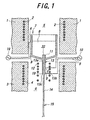
- FIG. 1 is a schematic sectional view of a manufacturing apparatus for growing a single crystal.
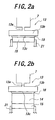
- FIGS. 2(a) and (b) represent steps of pulling down a planar body of the single crystal.
- a crucible 7 is placed in a furnace body.
- An upper furnace unit is arranged to surround the crucible 7 and an upper space 5 thereof, and has a heater 2 buried therein.
- a nozzle 13 extends downwardly from a bottom part of the crucible 7.
- the nozzle 13 comprises a connecting-tube portion 13a and a planar expanded portion 13b at the lower end of the connecting-tube portion 13a. In FIG.1, only a cross sectional view of the planar expanded portion 13b is shown.
- the connecting-tube portion 13a and the planar expanded portion 13b can be changed variously in shape. Both 13a and 13b can also be arbitrarily changed in combination.
- a slender opening 13c is formed at the lower end of the planar expanded portion 13b, and a vicinity of the opening 13c is a single crystal-growing portion 19.
- a lower furnace unit 3 is arranged to surround the nozzle 13 and a surrounding space 6 thereof, and has a heater 4 buried therein.
- the crucible 7 and the nozzle 13 are both formed from a corrosion-resistant conductive material.
- One electrode of a power source 10 is connected to a point A of the crucible 7 with an electric cable 9, and the other electrode of the power source 10 is connected to a lower bent B of the crucible 7.
- One electrode of an another power source 10 is connected to a point C of the connecting-tube portion 13a with an electric cable 9, and the other electrode of the power source 10 is connected to a lower end D of the planar expanded portion 13b.
- An after-heater 12 is located in the space 6 to surround the nozzle 13 with a distance.
- An intake tube 11 extends upwardly in the crucible 7 and an intake opening 22 is provided at the upper end of the intake tube 11. The intake opening 22 slightly protrudes from a bottom portion of a melt 8.
- the upper furnace unit 1, the lower furnace unit 3 and the after-heater 12 are allowed to heat for setting an appropriate temperature distribution in each of the space 5 and space 6. Then a raw material for the melt is supplied into the crucible 7 and the electricity is supplied to the crucible 7 and the nozzle 13 for heating. In this condition, the melt slightly protrudes from the opening 13c at the single crystal-growing portion 19.
- a planar seed crystal 15 is held with a holder 21 at both side faces and moved upwardly as shown in FIG. 2(a), and the upper surface of the seed crystal 15 is contacted with the melt protruding from the opening 13c. At that time, a uniform solid phase-liquid phase interface (meniscus) is formed between the upper end of the seed crystal 15 and the melt 18 pulled downwardly from the nozzle 13. Then, the seed crystal 15 is lowered as shown in FIG. 2(b). As a result, a planar body 14 is continuously formed on an upper side of the seed crystal 15 and pulled downwardly.
- the lattice constant is measured by an X-ray diffraction apparatus (MRD diffractometer, manufactured by Philips). If an unequivalent crystal axis exists in an oxide single crystal, differences in lattice constants between each crystal axis of the seed crystal and each corresponding axis of the planar body, respectively, have to be 0.1 % or less.
- An oxide single crystal is not particularly limited, but, for example, lithium potassium niobate (KLN), lithium potassium niobate-lithium potassium tantalate solid solution (KLTN : [K 3 Li 2-x (Ta y Nb 1-y ) 5+x O 15+2x ]), lithium niobate, lithium tantalate, lithium niobate-lithium tantalate solid solution, Ba 1-x Sr x Nb 2 O 6 , Mn-Zn ferrite, yttrium aluminum garnet substituted with Nd, Er and/or Yb, YAG, and YVO 4 substituted with Nd, Er, and/or Yb can be exemplified.
- a planar body of a lithium potassium niobate single crystal was produced according to the invention. Specifically, the temperature of the whole furnace was controlled by the upper furnace unit 1 and the lower furnace unit 3. The apparatus was configured to be able to control the temperature gradient near the single crystal-growing portion 19 by an electric supply to the nozzle 13 and the heat generation of the after-heater 12.
- a mechanism of pulling down the single crystal plate was equipped, in which a single crystal plate was pulled down with controlling the pulling-down rate uniformly within a range from 2 to 100 mm/hour in a vertical direction.
- a planar seed crystal 15 of lithium potassium niobate was used.
- a size of the seed crystal 15 was 30mm ⁇ lmm in cross-section and 5 mm in length.
- Lattice constants of the seed crystal 15 were 12.568 ⁇ in a-axis and 4.031 ⁇ in c-axis.
- the molar ratio of potassium, lithium and niobium was 30 : 18.2 : 51.8.
- a half width of an X-ray rocking curve was 60 seconds at 0 0 4 reflection of the seed crystal (measured by the MRD diffractometer, manufactured by Philips).
- Potassium carbonate, lithium carbonate and niobium pentoxide were prepared at a molar ratio of 30 : 26 : 44 to produce a raw material powder.
- the raw material was supplied into the platinum crucible 7, and the crucible 7 was set in place. With controlling the temperature of the space 5 in the upper furnace unit 1 within a range from 1100 to 1200°C, the raw material in the crucible 7 was melted.
- the temperature of the space 6 in the lower furnace unit 3 was controlled uniformly within a range from 500 to 1000°C. While a given electric power was supplied to each of the crucible 7, the nozzle 13 and the after-heater 12, a single crystal was grown. In this case, the temperature of the single crystal growing portion could be at 980 - 1150°C, and the temperature gradient of the single crystal growing portion could be controlled at 10 - 150°C/mm.
- the crucible 7 had an elliptical cross-sectional shape, wherein the major axis, the minor axis and the height was 50mm, 10mm and 10mm, respectively.
- the length of the connecting-tube portion was 5mm.
- a cross-sectional dimension of the planar expanded portion 13b was lmm ⁇ 50mm.
- a dimension of the opening 13c was 1mm long x 50mm wide. Under such conditions, the seed crystal 15 was pulled down at a rate of 10 mm/hour.
- Example 1 Similar results as Example 1 were obtained with a plate of lithium potassium niobate-lithium potassium tantalate solid solution single crystal.
- a planar body of lithium niobate was grown according to Example 1 except that a planar seed crystal 15 of lithium niobate was used. Dimensions of the seed crystal 15 were 50 mm ⁇ 1 mm in cross-section and 5mm in length.
- the seed crystal was cut out and obtained from a stoichiometric lithium niobate single crystal grown by the Czochralski method, wherein a direction of pulling down the seed crystal was set parallel to the X-axis, and a direction of a growing face was set parallel to the Z-axis.
- a lattice constant of the seed crystal was 5.148 ⁇ in a-axis and 13.857 ⁇ in c-axis.
- a molar ratio of lithium and niobium was 50 : 50, respectively.
- a half width of an X-ray rocking curve was 12 seconds at 0 0 12 reflection of the seed crystal.
- Lithium carbonate and niobium pentoxide were prepared at the molar ratio of 58 : 42 to produce a raw material powder.
- the raw material was fed into the platinum crucible 7, and the crucible 7 was arranged in a predetermined place. While a temperature of the space 5 in the upper furnace unit 1 was controlled within a range from 1200 to 1300°C, the raw material in the crucible 7 was melted. A temperature of the space 6 in the lower furnace unit 3 was controlled uniformly within a range from 500 to 1000°C. While a predetermined electric power was supplied to each of the crucible 7, the nozzle 13 and the after-heater 12, a single crystal was grown.
- the temperature of the single crystal-growing portion could be at 1200 - 1250°C, and the temperature gradient of the single crystal growing portion could be controlled at 10 - 150°C/mm.
- the seed crystal was lowered at a rate of 30 mm/hour.
- a volume of the crystallized lithium niobate was measured to convert it to a weight at each unit time internally, and the raw material of lithium niobate in equal weight to the converted one was supplied into the crucible.
- the lithium niobate powder supplied afterward in such manner was prepared to have a molar ratio of lithium and niobium at 50 : 50.
- a planar body having the width of 50 mm was formed without a shoulder portion. While the raw material powder of lithium niobate was fed, the crystal was continuously grown until a length of the planar body reached 50 mm. Then the planar body was cut off from the nozzle 13 and cooled.
- a composition of the obtained planar body (Z-plate) was measured by an inductively coupled plasma method, and a molar ratio of lithium and niobium was 50 : 50, which corresponded to the stoichiometry composition.
- a lattice constant of the planar body was measured to give an a-axis length of 5.148 ⁇ and the c-axis length of 13.858 ⁇ . Differences of lattice constants between the planar body and the seed crystal (lattice mismatch) were 0.01% or less in a-axis and 0.01% or less in c-axis. No cracks occurred at the joining portion between the seed crystal 15 and the planar body 14.
- a half width of an X-ray rocking curve was 12 seconds at the planar body.
- a planar body (X-plate) was grown according to Example 3 except that the seed crystal was worked so that a direction of pulling down the planar seed crystal might be parallel to the Z-axis, and that a direction of a growing face might be parallel to the X-axis.
- An a-axis length, a c-axis length and a half width of X-ray rocking curve at the seed crystal and the shoulder portion, were similar to those in Example 3. No cracks also occurred at the joining face between the shoulder portion and the seed crystal.
Landscapes
- Chemical & Material Sciences (AREA)
- Engineering & Computer Science (AREA)
- Crystallography & Structural Chemistry (AREA)
- Materials Engineering (AREA)
- Metallurgy (AREA)
- Organic Chemistry (AREA)
- Inorganic Chemistry (AREA)
- Crystals, And After-Treatments Of Crystals (AREA)
- Optical Modulation, Optical Deflection, Nonlinear Optics, Optical Demodulation, Optical Logic Elements (AREA)
Applications Claiming Priority (2)
| Application Number | Priority Date | Filing Date | Title |
|---|---|---|---|
| JP2000065123 | 2000-03-09 | ||
| JP2000065123A JP2001253792A (ja) | 2000-03-09 | 2000-03-09 | 酸化物単結晶の板状体の製造方法 |
Publications (1)
| Publication Number | Publication Date |
|---|---|
| EP1138808A1 true EP1138808A1 (en) | 2001-10-04 |
Family
ID=18584705
Family Applications (1)
| Application Number | Title | Priority Date | Filing Date |
|---|---|---|---|
| EP01302032A Withdrawn EP1138808A1 (en) | 2000-03-09 | 2001-03-06 | Process for producing a planar body of an oxide single crystal |
Country Status (3)
| Country | Link |
|---|---|
| US (1) | US6451110B2 (enExample) |
| EP (1) | EP1138808A1 (enExample) |
| JP (1) | JP2001253792A (enExample) |
Cited By (1)
| Publication number | Priority date | Publication date | Assignee | Title |
|---|---|---|---|---|
| EP1143041A1 (en) * | 2000-03-09 | 2001-10-10 | Ngk Insulators, Ltd. | Process for producing a planar body of an oxide single crystal |
Families Citing this family (3)
| Publication number | Priority date | Publication date | Assignee | Title |
|---|---|---|---|---|
| EP2221608B1 (de) * | 2009-02-18 | 2015-08-12 | F. Hoffmann-La Roche AG | Testverfahren zur Untersuchung einer Körperflüssigkeit |
| JP2021172575A (ja) * | 2020-04-30 | 2021-11-01 | Tdk株式会社 | 坩堝および結晶製造装置 |
| JP2022110664A (ja) * | 2021-01-19 | 2022-07-29 | Tdk株式会社 | 坩堝、結晶体および光学素子 |
Citations (4)
| Publication number | Priority date | Publication date | Assignee | Title |
|---|---|---|---|---|
| FR2321326A1 (fr) * | 1975-08-08 | 1977-03-18 | Ugine Kuhlmann | Procede de fabrication en continu de monocristaux preformes |
| EP0737884A2 (en) * | 1995-04-10 | 1996-10-16 | Ngk Insulators, Ltd. | Second harmonic generation element and a process for producing the same |
| JPH08319191A (ja) * | 1995-03-22 | 1996-12-03 | Ngk Insulators Ltd | 酸化物単結晶の製造方法および装置 |
| US5961720A (en) * | 1995-03-22 | 1999-10-05 | Ngk Insulators, Ltd. | Single crystal-growing apparatus |
Family Cites Families (4)
| Publication number | Priority date | Publication date | Assignee | Title |
|---|---|---|---|---|
| US3977071A (en) * | 1969-09-29 | 1976-08-31 | Texas Instruments Incorporated | High depth-to-width ratio etching process for monocrystalline germanium semiconductor materials |
| US4040868A (en) * | 1976-03-09 | 1977-08-09 | General Electric Company | Semiconductor device manufacture |
| US4128616A (en) * | 1977-08-11 | 1978-12-05 | Bell Telephone Laboratories, Incorporated | Micropositioners using a crystal having moveable domain walls |
| US4170490A (en) * | 1978-12-07 | 1979-10-09 | General Electric Company | Process for thermal gradient zone melting utilizing a beveled wafer edge |
-
2000
- 2000-03-09 JP JP2000065123A patent/JP2001253792A/ja active Pending
-
2001
- 2001-03-05 US US09/799,309 patent/US6451110B2/en not_active Expired - Fee Related
- 2001-03-06 EP EP01302032A patent/EP1138808A1/en not_active Withdrawn
Patent Citations (4)
| Publication number | Priority date | Publication date | Assignee | Title |
|---|---|---|---|---|
| FR2321326A1 (fr) * | 1975-08-08 | 1977-03-18 | Ugine Kuhlmann | Procede de fabrication en continu de monocristaux preformes |
| JPH08319191A (ja) * | 1995-03-22 | 1996-12-03 | Ngk Insulators Ltd | 酸化物単結晶の製造方法および装置 |
| US5961720A (en) * | 1995-03-22 | 1999-10-05 | Ngk Insulators, Ltd. | Single crystal-growing apparatus |
| EP0737884A2 (en) * | 1995-04-10 | 1996-10-16 | Ngk Insulators, Ltd. | Second harmonic generation element and a process for producing the same |
Non-Patent Citations (3)
| Title |
|---|
| CHANI V I ET AL: "SEGREGATION AND UNIFORMITY OF K3LI2(TA,NB)5O15 FIBER CRYSTALS GROWN BY MICRO-PULLING-DOWN METHOD", JOURNAL OF CRYSTAL GROWTH,NL,NORTH-HOLLAND PUBLISHING CO. AMSTERDAM, vol. 194, no. 3/04, December 1998 (1998-12-01), pages 374 - 378, XP000669101, ISSN: 0022-0248 * |
| PATENT ABSTRACTS OF JAPAN vol. 1997, no. 04 30 April 1997 (1997-04-30) * |
| RUDD ET AL.: "Growth of lithium tantalate...", SOLID STATE TECHNOLOGY., vol. 17, no. 1, January 1974 (1974-01-01), COWAN PUBL.CORP. WASHINGTON., US, pages 52 - 55, XP002171183, ISSN: 0038-111X * |
Cited By (1)
| Publication number | Priority date | Publication date | Assignee | Title |
|---|---|---|---|---|
| EP1143041A1 (en) * | 2000-03-09 | 2001-10-10 | Ngk Insulators, Ltd. | Process for producing a planar body of an oxide single crystal |
Also Published As
| Publication number | Publication date |
|---|---|
| US6451110B2 (en) | 2002-09-17 |
| US20010025599A1 (en) | 2001-10-04 |
| JP2001253792A (ja) | 2001-09-18 |
Similar Documents
| Publication | Publication Date | Title |
|---|---|---|
| Yoon et al. | Morphological aspects of potassium lithium niobate crystals with acicular habit grown by the micro-pulling-down method | |
| US6673330B1 (en) | Single crystal of lithium niobate or tantalate and its optical element, and process and apparatus for producing an oxide single crystal | |
| US6451110B2 (en) | Process for producing a planar body of an oxide single crystal | |
| Prokofiev et al. | Growth of single-crystal photorefractive fibers of Bi12SiO20 and Bi12TiO20 by the laser-heated pedestal growth method | |
| US6527851B2 (en) | Process for producing a planar body of an oxide single crystal | |
| Yoon | Crystal growth of the oxide fiber single crystal for optical applications | |
| Bonner et al. | Effects of changes in melt composition on crystal growth of barium sodium niobate | |
| EP1170403B1 (en) | Process and apparatus for producing a planar body of an oxide single crystal | |
| EP1132503B1 (en) | Process and apparatus for producing oxide single crystals | |
| Fukuda et al. | Crystal growth of oxide and fluoride materials for optical, piezoelectric and other applications | |
| JP4312341B2 (ja) | 酸化物単結晶の板状体の製造方法、これに使用する種結晶および種結晶の保持具 | |
| EP1160359B1 (en) | Process and appparatus for producing an oxide single crystal | |
| Lebbou et al. | Effect of gadolinium (Gd3+) addition on the monophased field and crystal growth of Ba2NaNb5O15 (BNN) | |
| Chani et al. | Growth of K3Li2Nb5O15 and KNbO3 ferroelectric fiber crystals by pulling-down technique | |
| JP3037829B2 (ja) | 単結晶育成方法および単結晶 | |
| JP2738641B2 (ja) | X軸方位ニオブ酸リチウム単結晶の製造方法 | |
| Imaeda et al. | K3Li2Nb5O15 fiber and plate crystals | |
| JP6401673B2 (ja) | 単結晶成長方法およびその装置 | |
| Rudolph | What do we want with fiber crystals? An introductory overview | |
| JP2001158692A (ja) | 波長変換素子 | |
| JPH10101487A (ja) | 光学用四ほう酸リチウム単結晶の育成方法 | |
| Adachi et al. | Growth and properties of tungsten-bronze ferroelectric potassium lithium niobate single crystals for optical applications | |
| JPH0545689A (ja) | 導波路型非線形光学デバイス | |
| Kumatoriya | Studies of Influence of Compositional Modification on Electrical and Optical Properties of Inorganic Materials | |
| JPH10259096A (ja) | 光学用四ほう酸リチウム単結晶の育成方法 |
Legal Events
| Date | Code | Title | Description |
|---|---|---|---|
| PUAI | Public reference made under article 153(3) epc to a published international application that has entered the european phase |
Free format text: ORIGINAL CODE: 0009012 |
|
| AK | Designated contracting states |
Kind code of ref document: A1 Designated state(s): AT BE CH CY DE DK ES FI FR GB GR IE IT LI LU MC NL PT SE TR Kind code of ref document: A1 Designated state(s): DE FR GB |
|
| AX | Request for extension of the european patent |
Free format text: AL;LT;LV;MK;RO;SI |
|
| 17P | Request for examination filed |
Effective date: 20020325 |
|
| AKX | Designation fees paid |
Free format text: DE FR GB |
|
| 17Q | First examination report despatched |
Effective date: 20060529 |
|
| STAA | Information on the status of an ep patent application or granted ep patent |
Free format text: STATUS: THE APPLICATION IS DEEMED TO BE WITHDRAWN |
|
| 18D | Application deemed to be withdrawn |
Effective date: 20080122 |