EP1138457A2 - Dispositif et procédé pour la fabrication d'un récipient de stockage ou transport ou une palette en matière plastique - Google Patents
Dispositif et procédé pour la fabrication d'un récipient de stockage ou transport ou une palette en matière plastique Download PDFInfo
- Publication number
- EP1138457A2 EP1138457A2 EP01107689A EP01107689A EP1138457A2 EP 1138457 A2 EP1138457 A2 EP 1138457A2 EP 01107689 A EP01107689 A EP 01107689A EP 01107689 A EP01107689 A EP 01107689A EP 1138457 A2 EP1138457 A2 EP 1138457A2
- Authority
- EP
- European Patent Office
- Prior art keywords
- gas
- tool part
- spray chamber
- slides
- plastic
- Prior art date
- Legal status (The legal status is an assumption and is not a legal conclusion. Google has not performed a legal analysis and makes no representation as to the accuracy of the status listed.)
- Withdrawn
Links
Images


Classifications
-
- B—PERFORMING OPERATIONS; TRANSPORTING
- B29—WORKING OF PLASTICS; WORKING OF SUBSTANCES IN A PLASTIC STATE IN GENERAL
- B29C—SHAPING OR JOINING OF PLASTICS; SHAPING OF MATERIAL IN A PLASTIC STATE, NOT OTHERWISE PROVIDED FOR; AFTER-TREATMENT OF THE SHAPED PRODUCTS, e.g. REPAIRING
- B29C45/00—Injection moulding, i.e. forcing the required volume of moulding material through a nozzle into a closed mould; Apparatus therefor
- B29C45/17—Component parts, details or accessories; Auxiliary operations
- B29C45/1703—Introducing an auxiliary fluid into the mould
- B29C45/1704—Introducing an auxiliary fluid into the mould the fluid being introduced into the interior of the injected material which is still in a molten state, e.g. for producing hollow articles
- B29C45/1705—Introducing an auxiliary fluid into the mould the fluid being introduced into the interior of the injected material which is still in a molten state, e.g. for producing hollow articles using movable mould parts
-
- B—PERFORMING OPERATIONS; TRANSPORTING
- B29—WORKING OF PLASTICS; WORKING OF SUBSTANCES IN A PLASTIC STATE IN GENERAL
- B29L—INDEXING SCHEME ASSOCIATED WITH SUBCLASS B29C, RELATING TO PARTICULAR ARTICLES
- B29L2031/00—Other particular articles
- B29L2031/712—Containers; Packaging elements or accessories, Packages
- B29L2031/7178—Pallets
Definitions
- the invention relates to a device for producing a bearing or Transport container or a pallet made of plastic with closed cavities in at least one bottom or side wall, according to the generic term of claim 1 and a method for producing a bearing or Transport container or a pallet made of plastic with closed Cavities in at least one bottom or side wall with this device.
- DE 94 21 487 U1 describes a method for producing a bearing or Transport container known, in which the spray chamber in an injection mold, in which the corresponding bottom or side wall is formed is completely filled with plasticized plastic material. Then, by blowing gas under pressure into the Spray cavity formed a cavity.
- the cavities extend across the total length or width of the bottom or side wall, with a single Cavity or several cavities arranged parallel to one another are provided are.
- the shape of the corresponding spray chamber section corresponds to the shape of the Bottom or side wall of the finished plastic container. Since the Spray room for the production of the plastic container completely with plastic material is filled, the plastic material must be when the gas is injected be compressed to form the cavities. This compression is only possible to a certain extent, so that the cavity walls a have increased thickness. As a result, the cost of materials and the Weight of the plastic container increased. In addition, a high pressure is Cavity formation required.
- DE 195 18 153 A1 describes a device for producing a bearing or Transport container with closed cavities in the bottom wall known, which comprises a first tool part and a second tool part, between which a spray chamber is formed in the closed state. On The slide extends into the spray chamber in an extended position and is in retracted into the first tool part. Gas needles one Pressurized gas device for blowing gas into the spray chamber for example at injection sites, each one a single chamber of the soil are assigned.
- DE 196 35 954 A1 describes a device for producing a Injection molded plastic part with a hollow thick part, in which in a tool part several sliders arranged side by side are provided. Neighbors Sliders are separated from each other by a secondary channel. In the Spray chamber open approximately in the middle of the lower end face of each slide Gas nozzles.
- the invention has for its object a structurally simple device as well as to provide a reliable process that enable with a storage or transport container or a pallet made of plastic high stability and low weight in a simple manner.
- the plastic material in the device according to the invention, by pulling in the slide an additional space is formed for the formation of the cavities, so that the Plastic material does not have to be compressed.
- the plastic material can attaches to the inner walls of the cavity with a relatively thin wall thickness invest. Since the compressed gas via the at least one gas needle in the to Slider adjacent gas distribution channel is inserted, it is possible to Form cavities with a relatively small number of gas needles, so that the device is structurally simple. Due to the gas channel a gas needle cannot be assigned to each cavity. It may be sufficient with a single gas needle pressurized gas into the gas distribution channel blow in. A gas breakdown from the gas distribution channel to the corresponding one Cavity can take place after pulling in the respective slide.
- the storage or transport container 10 shown in FIGS. 1 and 2 Plastic has two opposite transverse side walls 12, 14 and these perpendicular longitudinal side walls 16, 18 and a bottom wall 20. Adjacent to each long side wall 16, 18th a series of cavities 22 is provided within the bottom wall 20, the one seen from the bottom is essentially rectangular Have cross-section. Adjacent cavities 22 are each marked by a Crossbar 26 separated from each other. On the of the corresponding longitudinal edge 16, 18 facing away from the cavities 22 by a parallel to the longitudinal side wall 16, 18 between the two transverse side walls 12, 14 extending longitudinal web 24 limited. The boundary of the cavities 22 along of the longitudinal side edge 16 or 18 is by a longitudinal edge web 28th educated. The cavities 22 provided in the corner area are on the Transverse side walls 12, 14 delimited by a transverse edge web 30.
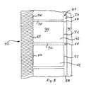
- the storage and transport container shown in Figs. 1 and 2 made of plastic 10 is produced with an injection mold 32, the area in which the cavities 22 of the storage and transport container 10 are formed in 3 to 8 is shown.
- the injection molding tool points in this area 32 a lower tool part 34, an upper tool part 36 and a lateral tool part 38, between which a spray chamber 40 is formed in which the bottom 20 and a longitudinal side wall 16, 18 through Injection molding.
- the injection mold 32 is in its initial position shown.
- the recess 41 is located in the area in which the row of cavities 22 of the Storage and transport container 10 are formed. At the positions of each The cavity 22 is a cuboid within the recess 41 Slider 42 perpendicular to surface 46 of lower tool part 34 slidably mounted.
- the upper surface 44 of the slider 42 is located in the starting position of the injection mold shown in FIGS. 3 and 8 32 flush with the upper surface 46 of the lower tool part 34 and in Distance to the upper tool part 36.
- All secondary channels 50 open into one common gas distribution channel 48 through the inner side walls 52 of the slide 42, the side wall 54 and the bottom 58 are formed becomes.
- the secondary channels 50 open into an edge channel 60, through the outer side wall 62 of the slider 42, the outer side wall 56 of the recess 41 and the bottom 58 is formed.
- Gas distribution channel 48 is at least one gas needle passage opening 64 arranged, which opens into the bottom 58 of the recess.
- a gas needle is then passed through the gas needle passage opening 64 68 inserted into the gas distribution channel 48 (Fig. 5).
- a gas with high pressure is injected into the gas needle 68 Gas distribution channel 48 introduced.
- the tip of the gas needle 68 is located in the plastic material at the level of the gap between the upper tool part 36 and the lower tool part 34.
- a cavity 72 is formed in the plastic material through the plastic material in the secondary channels 50, the edge channel 60 and in the gas distribution channel 48 as well as the plastic material that is attached to the Top 54 of the slide 42 creates. This is shown in Figure 7.
- the injection mold 32 opened and the finished storage or transport container 10 from the injection mold 32 taken out.
Landscapes
- Engineering & Computer Science (AREA)
- Manufacturing & Machinery (AREA)
- Mechanical Engineering (AREA)
- Injection Moulding Of Plastics Or The Like (AREA)
- Moulds For Moulding Plastics Or The Like (AREA)
- Pallets (AREA)
Applications Claiming Priority (2)
| Application Number | Priority Date | Filing Date | Title |
|---|---|---|---|
| DE10015313 | 2000-03-28 | ||
| DE2000115313 DE10015313B4 (de) | 2000-03-28 | 2000-03-28 | Vorrichtung und Verfahren zur Herstellung eines Lager- oder Transportbehälters oder einer Palette aus Kunststoff |
Publications (2)
| Publication Number | Publication Date |
|---|---|
| EP1138457A2 true EP1138457A2 (fr) | 2001-10-04 |
| EP1138457A3 EP1138457A3 (fr) | 2002-03-20 |
Family
ID=7636647
Family Applications (1)
| Application Number | Title | Priority Date | Filing Date |
|---|---|---|---|
| EP01107689A Withdrawn EP1138457A3 (fr) | 2000-03-28 | 2001-03-28 | Dispositif et procédé pour la fabrication d'un récipient de stockage ou transport ou une palette en matière plastique |
Country Status (2)
| Country | Link |
|---|---|
| EP (1) | EP1138457A3 (fr) |
| DE (1) | DE10015313B4 (fr) |
Family Cites Families (5)
| Publication number | Priority date | Publication date | Assignee | Title |
|---|---|---|---|---|
| DE4002503C1 (en) * | 1990-01-29 | 1991-05-29 | Schade Kg, 5970 Plettenberg, De | Hollow injection moulded plastic mouldings prodn. - comprising injecting plastic melt into mould and applying pressurised gas to melt, using variable cross=sectioned mould |
| DE4128883A1 (de) * | 1990-10-31 | 1993-03-04 | Delbrouck Franz Gmbh | Flachpalette |
| DE4406676A1 (de) * | 1994-03-01 | 1995-09-07 | Schoeller Plast Ag | Ladungsträger, insbesondere Behälter, Paletten und dergleichen |
| DE19518153B4 (de) * | 1995-05-17 | 2006-04-06 | Ninkaplast Gmbh | Verfahren zur Herstellung eines Schubkastens |
| DE19635954C2 (de) * | 1996-09-05 | 2003-06-18 | Schoeller Wavin Sys Serv Gmbh | Spritzgießform und Verfahren zur Herstellung eines Spritzgießteiles mit einer hohlen Dickstelle |
-
2000
- 2000-03-28 DE DE2000115313 patent/DE10015313B4/de not_active Expired - Fee Related
-
2001
- 2001-03-28 EP EP01107689A patent/EP1138457A3/fr not_active Withdrawn
Also Published As
| Publication number | Publication date |
|---|---|
| DE10015313B4 (de) | 2004-03-18 |
| EP1138457A3 (fr) | 2002-03-20 |
| DE10015313A1 (de) | 2001-10-18 |
Similar Documents
| Publication | Publication Date | Title |
|---|---|---|
| DE69219157T2 (de) | Spritzgiessen von kunststoffgegenständen die hohlförmige rippen aufweisen | |
| DE2802237C2 (de) | Spritzgießform zum Herstellen von aus mindestens zwei verschiedenen Kunststoffmassen bestehenden und mindestens zwei unterschiedliche Bereiche aufweisenden Spritzgußteilen | |
| EP0440020B1 (fr) | Procédé pour fabriquer des corps creux moulés par injection en matière plastique et dispositif pour la mise en oeuvre du procédé | |
| EP1575830A1 (fr) | Dispositif pour produire des paquets de cigarettes | |
| DE1778371B1 (de) | Vorrichtung zum herstellen von gegenstaenden aus faserigen zuschnitten die mit einem waermehaertbaren kunststoff ge traenkt sind und deren laenge sehr viel groesser ist als ihre breite | |
| DE10252648A1 (de) | Behältnis sowie Anlage und Verfahren zum Ausbilden dieses | |
| EP0667109B1 (fr) | Etui de protection pour cartes | |
| EP0738661B1 (fr) | Procèdè et dispositif pour la fabrication d'une pallette en matière plastique | |
| DE10015313B4 (de) | Vorrichtung und Verfahren zur Herstellung eines Lager- oder Transportbehälters oder einer Palette aus Kunststoff | |
| WO1990000647A1 (fr) | Procede de fabrication de traverses d'aiguillage en beton pour chemins de fer | |
| DE4128883A1 (de) | Flachpalette | |
| AT403676B (de) | Hohlform zur herstellung von hohlkörpern mit von handgriffen überspannten griffmulden aus thermoplastischem werkstoff | |
| DE19635954C2 (de) | Spritzgießform und Verfahren zur Herstellung eines Spritzgießteiles mit einer hohlen Dickstelle | |
| DE2512474A1 (de) | Fuehrungsvorrichtung und verfahren zu ihrer herstellung | |
| EP0853812B1 (fr) | Procede et dispositif destine au montage final d'un clavier d'ordinateur | |
| DE19518153A1 (de) | Schubkasten | |
| DE4330998A1 (de) | Transportkasten aus Kunststoff | |
| DE19537142C1 (de) | Spritzgießform für eine Vielzahl individueller Formteile, insbesondere Tastenkörper | |
| DE102013102325A1 (de) | Verfahren und Vorrichtung zur Herstellung großflächiger Hohlkörper | |
| DE19545030A1 (de) | Vorrichtung zum Herstellen von Bürsten und danach hergestellte Bürsten | |
| DE2130135B2 (de) | Im Spritzgießverfahren hergestellter Kunststoffkasten mit Innenzellen, insbesondere Batteriekasten | |
| EP1551606A1 (fr) | Dispositif pour produire des ebauches en beton presentant une surface rugueuse et ebauche en beton | |
| DE1529873C (de) | Spritzgießform zur Herstellung einer Fußbettsohle aus einem blahbaren Werkstoff | |
| EP1342546B1 (fr) | Moule d'injection avec un noyau de segments mobile | |
| DE19544306C1 (de) | Verfahren zur Herstellung von miteinander lösbar verbindbaren Kunststoffteilen sowie Verbundteil |
Legal Events
| Date | Code | Title | Description |
|---|---|---|---|
| PUAI | Public reference made under article 153(3) epc to a published international application that has entered the european phase |
Free format text: ORIGINAL CODE: 0009012 |
|
| AK | Designated contracting states |
Kind code of ref document: A2 Designated state(s): DE IT NL Kind code of ref document: A2 Designated state(s): AT BE CH CY DE DK ES FI FR GB GR IE IT LI LU MC NL PT SE TR |
|
| AX | Request for extension of the european patent |
Free format text: AL;LT;LV;MK;RO;SI |
|
| PUAL | Search report despatched |
Free format text: ORIGINAL CODE: 0009013 |
|
| AK | Designated contracting states |
Kind code of ref document: A3 Designated state(s): AT BE CH CY DE DK ES FI FR GB GR IE IT LI LU MC NL PT SE TR |
|
| AX | Request for extension of the european patent |
Free format text: AL;LT;LV;MK;RO;SI |
|
| 17P | Request for examination filed |
Effective date: 20020507 |
|
| 17Q | First examination report despatched |
Effective date: 20020917 |
|
| AKX | Designation fees paid |
Free format text: DE IT NL |
|
| GRAH | Despatch of communication of intention to grant a patent |
Free format text: ORIGINAL CODE: EPIDOS IGRA |
|
| STAA | Information on the status of an ep patent application or granted ep patent |
Free format text: STATUS: THE APPLICATION IS DEEMED TO BE WITHDRAWN |
|
| 18D | Application deemed to be withdrawn |
Effective date: 20030702 |