EP1135238B1 - Industrial robot according to the delta concept with a rotatable telescopic axle - Google Patents
Industrial robot according to the delta concept with a rotatable telescopic axle Download PDFInfo
- Publication number
- EP1135238B1 EP1135238B1 EP99963794A EP99963794A EP1135238B1 EP 1135238 B1 EP1135238 B1 EP 1135238B1 EP 99963794 A EP99963794 A EP 99963794A EP 99963794 A EP99963794 A EP 99963794A EP 1135238 B1 EP1135238 B1 EP 1135238B1
- Authority
- EP
- European Patent Office
- Prior art keywords
- axle
- industrial robot
- outer tube
- robot according
- inner axle
- Prior art date
- Legal status (The legal status is an assumption and is not a legal conclusion. Google has not performed a legal analysis and makes no representation as to the accuracy of the status listed.)
- Expired - Lifetime
Links
Images

Classifications
-
- F—MECHANICAL ENGINEERING; LIGHTING; HEATING; WEAPONS; BLASTING
- F16—ENGINEERING ELEMENTS AND UNITS; GENERAL MEASURES FOR PRODUCING AND MAINTAINING EFFECTIVE FUNCTIONING OF MACHINES OR INSTALLATIONS; THERMAL INSULATION IN GENERAL
- F16C—SHAFTS; FLEXIBLE SHAFTS; ELEMENTS OR CRANKSHAFT MECHANISMS; ROTARY BODIES OTHER THAN GEARING ELEMENTS; BEARINGS
- F16C3/00—Shafts; Axles; Cranks; Eccentrics
- F16C3/02—Shafts; Axles
- F16C3/03—Shafts; Axles telescopic
- F16C3/035—Shafts; Axles telescopic with built-in bearings
-
- B—PERFORMING OPERATIONS; TRANSPORTING
- B23—MACHINE TOOLS; METAL-WORKING NOT OTHERWISE PROVIDED FOR
- B23Q—DETAILS, COMPONENTS, OR ACCESSORIES FOR MACHINE TOOLS, e.g. ARRANGEMENTS FOR COPYING OR CONTROLLING; MACHINE TOOLS IN GENERAL CHARACTERISED BY THE CONSTRUCTION OF PARTICULAR DETAILS OR COMPONENTS; COMBINATIONS OR ASSOCIATIONS OF METAL-WORKING MACHINES, NOT DIRECTED TO A PARTICULAR RESULT
- B23Q1/00—Members which are comprised in the general build-up of a form of machine, particularly relatively large fixed members
- B23Q1/25—Movable or adjustable work or tool supports
- B23Q1/44—Movable or adjustable work or tool supports using particular mechanisms
- B23Q1/50—Movable or adjustable work or tool supports using particular mechanisms with rotating pairs only, the rotating pairs being the first two elements of the mechanism
- B23Q1/54—Movable or adjustable work or tool supports using particular mechanisms with rotating pairs only, the rotating pairs being the first two elements of the mechanism two rotating pairs only
- B23Q1/545—Movable or adjustable work or tool supports using particular mechanisms with rotating pairs only, the rotating pairs being the first two elements of the mechanism two rotating pairs only comprising spherical surfaces
- B23Q1/5462—Movable or adjustable work or tool supports using particular mechanisms with rotating pairs only, the rotating pairs being the first two elements of the mechanism two rotating pairs only comprising spherical surfaces with one supplementary sliding pair
-
- B—PERFORMING OPERATIONS; TRANSPORTING
- B25—HAND TOOLS; PORTABLE POWER-DRIVEN TOOLS; MANIPULATORS
- B25J—MANIPULATORS; CHAMBERS PROVIDED WITH MANIPULATION DEVICES
- B25J17/00—Joints
- B25J17/02—Wrist joints
- B25J17/0258—Two-dimensional joints
- B25J17/0266—Two-dimensional joints comprising more than two actuating or connecting rods
-
- B—PERFORMING OPERATIONS; TRANSPORTING
- B25—HAND TOOLS; PORTABLE POWER-DRIVEN TOOLS; MANIPULATORS
- B25J—MANIPULATORS; CHAMBERS PROVIDED WITH MANIPULATION DEVICES
- B25J18/00—Arms
- B25J18/02—Arms extensible
- B25J18/025—Arms extensible telescopic
-
- B—PERFORMING OPERATIONS; TRANSPORTING
- B25—HAND TOOLS; PORTABLE POWER-DRIVEN TOOLS; MANIPULATORS
- B25J—MANIPULATORS; CHAMBERS PROVIDED WITH MANIPULATION DEVICES
- B25J9/00—Programme-controlled manipulators
- B25J9/003—Programme-controlled manipulators having parallel kinematics
- B25J9/0045—Programme-controlled manipulators having parallel kinematics with kinematics chains having a rotary joint at the base
- B25J9/0051—Programme-controlled manipulators having parallel kinematics with kinematics chains having a rotary joint at the base with kinematics chains of the type rotary-universal-universal or rotary-spherical-spherical, e.g. Delta type manipulators
-
- F—MECHANICAL ENGINEERING; LIGHTING; HEATING; WEAPONS; BLASTING
- F16—ENGINEERING ELEMENTS AND UNITS; GENERAL MEASURES FOR PRODUCING AND MAINTAINING EFFECTIVE FUNCTIONING OF MACHINES OR INSTALLATIONS; THERMAL INSULATION IN GENERAL
- F16C—SHAFTS; FLEXIBLE SHAFTS; ELEMENTS OR CRANKSHAFT MECHANISMS; ROTARY BODIES OTHER THAN GEARING ELEMENTS; BEARINGS
- F16C2322/00—Apparatus used in shaping articles
- F16C2322/50—Hand tools, workshop equipment or manipulators
- F16C2322/59—Manipulators, e.g. robot arms
Definitions
- the present invention relates to an industrial robot according to the delta concept with an arm system, as defined in the preamble of claim 1.
- the present invention also relates to a method for manufacturing an industrial robot according to the delta concept with an arm system intended to rotate in space, as defined in the preamble of claim 10, as well as to the use of such robot.
- This type of robot can, for example, be placed in a frame construction above a conveyor belt, and have an arm system to which tools intended to rotate in space, i.e. rotate with three degrees of freedom in x, y and z directions, can be attached.
- the arm system commonly comprises a base section, a moveable plate and, between them, several jointed pull rods. It is primarily the pull rods that take up the load.
- a telescopic axle, also called a fourth axle, is arranged between the base section and the moveable plate.
- Its task is to act as a driving axle from a motor in the robot structure to a tool arranged on the moveable plate.
- the rotation should have minimal loose play and be able to be carried out in free space, i.e. the distance from the moveable plate to the base of the robot, the base section, is variable.
- the linear movement can have a speed up to 10 m/s.
- the number of "pick-ups" of objects can be 120 pieces per minute, which is equivalent to 2 per second.
- this delta robot is usually equipped with a system that visually identifies defective objects and only selects those that are perfect.
- the telescopic axle must respectively decrease or increase its length at the same time as it is to transfer relatively large moments with great precision, high speed/acceleration, irrespective of whether the object to be picked up is placed at random on the conveyor belt or whether its position is controlled.
- an outer tube is joined to an inner axle with an ordinary sliding joint, for example, in the form of splines or similar means, which leads to loose play in the transfer of moments and that is not able to handle moments greater than about 0.5 Nm at moderate speeds.
- the present invention aims to achieve a device for an industrial robot that is more effective and faster than conventional designs.
- the objective of the invention is, for a telescopic arm, allow a low friction moment-transferring movement that is free of loose play and that is parallel.
- One goal of the present invention is thus to be able to perform a rotational movement in space with minimal friction, without loose play and with maximum rigidity with an arm system for an industrial robot.
- the rotational movement should be able to be performed at high speeds and acceleration and with relatively large moments.
- claim 1 relates to an industrial robot according to the delta concept with an arm system intended to rotate in space and that comprises a base section, a moveable plate, several multi-jointed pull rods and a telescopic axle arranged between the base section and the moveable plate, where opposite ends of the pull rods and the telescopic axle are connected with the base section and the moveable plate respectively, and where the telescopic axle comprises an inner axle and an outer tube arranged on the inner axle and displaceable relatively to the inner axle in a longitudinal direction, where a torsional rigid bushing is arranged in a stationary manner on the outer tube in which the inner axle is mounted to be displaceable.
- a preferred embodiment includes a guiding device for a telescopic axle with the characteristics stated in claim 6.
- the inner axle usually has a free axle end that is not fixed.
- the inner axle moves parallel with the outer tube.
- a further disadvantage is that a loading, a breaking force, occurs on the said torosional rigid bushing in that the inner axle tilts around the bushing. This problem is solved according to the present invention with an industrial robot with the characteristics stated in claim 6.
- a telescopic axle is achieved that eliminates problems of wear and dissonance, at the same time as a very torsional rigid design with reduced friction and loose play is achieved. Due to the solution with the guiding device, the parts of the telescopic arm, the inner axle and the outer tube, move parallel in relation to one another. The inner axle is prevented from tilting and causing a breaking force on the bushing.
- the torosional rigid bushing can, for example, be joined to the inner axle.
- balls or similar means be arranged within the bushing, where the balls can be located in grooves in the inner axle.
- One or more balls can, in this case, be arranged in each respective groove.
- the bushing is preferably a moment ball-bushing.
- the bushing and guiding device respectively can be designed in material suitable for the purpose such as thin steel plate, aluminium or plastic. In order for the guiding device to able to handle the wear that occurs, it is appropriate to mould it from a polymer such as POM, PE or PA.
- the guiding device can be designed as a disc, several shoulders, an annular sleeve or similar. According to one embodiment, the guiding device is disc-shaped and provided with through cavities in the thickness direction of the disc to allow air to pass through.
- the present invention also comprises a method according to claim 10 for manufacturing an industrial robot according to the delta concept with an arm system intended to rotate in space, whereby in the arm system a base section and a moveable plate are arranged, several multi-jointed pull rods and a telescopic axle are arranged between the base section and the moveable plate, where opposite ends of the pull rods and the telescopic axle are connected with the base section and the moveable plate respectively, and where the telescopic axle comprises an inner axle and an outer tube arranged on the inner axle and displaceable relatively to the inner axle in a longitudinal direction wherein a torsional rigid bushing is arranged in a stationary manner on the outer tube in which the inner axle is mounted to be displaceable.
- the method additionally comprises firmly attaching a guiding device to the inner axle, whereby one part of the said guiding device is arranged to abut the inside of the outer tube.
- the present invention also includes use of the said industrial robot, according to claim 12.
- the described industrial robot that can also be termed manipulator with controlling apparatus, is according to the present invention intended to be able to handle loads of up to at least 1 kg.
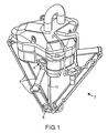
- Fig. 1 shows an industrial robot according to the delta concept.
- the industrial robot is designed with an arm system 2 intended to rotate in the space.
- a number of jointed pull rods 8 are arranged on a moveable plate 6 at their end sections.
- the jointed pull rods are arranged to a generally designated base section 4 of the robot at their opposite end sections.
- a tool is intended to be arranged on the moveable plate 6.
- a fourth axle in the form of a telescopic axle 10 is arranged between the base section and the moveable plate where the opposite ends of the telescopic axle 12, 14 (see Fig. 2) and the respective pull rods 8 are connected with the base section and the moveable plate respectively.
- the task of the telescopic axle is to act as a driving axle from a motor in the robot structure to a tool arranged on the moveable plate.
- the telescopic axle is arranged in a stationary manner on base section 4 and at its other end is able to move freely when it is arranged at moveable plate 6.
- the whole of the telescopic axle can move forwards and backwards at very high speeds.
- the rotation takes place in the space, i.e. the distance from moveable plate 6 to base section 4 is variable.
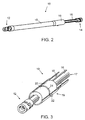
- Fig. 2 shows a view of a telescopic axle 10 that comprises an inner axle 16 with an end section 14 and an outer tube 18 with an end section 12 arranged on the inner axle and displaceable in a longitudinal direction.
- Outer tube 18 is designed with a thicker, sleeve-shaped section 19 that surrounds a torosional rigid bushing 20 (see Fig. 3) arranged at inner axle 16.
- a torsional rigid bushing 20 arranged, in which the inner axle is displaceable.
- outer tube 18 with end section 12 can be arranged on moveable plate 6 (see Fig. 1) and inner axle 16 with end section 14 can be arranged on base section 4 of the robot.
- a telescopic axle 10 with a torsional rigid bushing 20 is firmly attached to outer tube 18 and surrounds inner axle 16.
- the torsional rigid bushing can, for example, be mounted to the inner axle, whereby balls or the similar are placed in grooves 17 on the inner axle and arranged within the bushing. Grooves 17 also act to guide the bushing during the displacement of inner axle 16 in the bushing.
- the bushing can be an annular-shaped sleeve.
- a lubrication nipple 22 is arranged, and at the location of lubrication nipple 22, the bushing can suitably be cut through down to the inner axle with a slit 24 intended to accommodate excess lubricant for continuous lubrication of the inner axle during movement relative to the bushing.
- Fig. 4 illustrates a partially sectioned view of a guiding device 30 arranged on inner axle 16, preferably firmly attached to free end 31 of in the inner axle at a telescopic axle 10 (see Figs. 1-2).
- guiding device 30 can also be disc-shaped and be designed with through cavities 32 in the thickness direction of the disc to reduce air resistance, where cavities 32 in a radial direction can suitably be through channels that extend outwards and that are open at the periphery 33 of the guiding device, which allows the guiding device to be resilient against the outer tube when the guiding device is arranged to be pre-tensioned against the outer tube.
- the guiding device can be designed with several cavities 32.
- the guiding device is arranged to abut the inside or inner wall 34 of the inner tube.
- the guiding device can suitably be provided with shoulders 35 with bevelled edges intended to abut the inside 34 of the inner tube, and recess sections 36, to minimise the risk of skewing due to friction.
- Shoulders 35 can, for example, comprise three or four shoulders evenly spaced around the periphery of the guiding device.
- the guiding device is preferably arranged centrally within the outer tube. In addition, it is appropriate to arrange the guiding device pre-tensioned within the outer tube, which means that the diameter of the guiding device is somewhat greater than the inner diameter of the outer tube so that the guiding device presses against the inside 34 of the outer tube.
Landscapes
- Engineering & Computer Science (AREA)
- Mechanical Engineering (AREA)
- Robotics (AREA)
- General Engineering & Computer Science (AREA)
- Ocean & Marine Engineering (AREA)
- Manipulator (AREA)
- Forklifts And Lifting Vehicles (AREA)
- Bending Of Plates, Rods, And Pipes (AREA)
- Shafts, Cranks, Connecting Bars, And Related Bearings (AREA)
Applications Claiming Priority (3)
| Application Number | Priority Date | Filing Date | Title |
|---|---|---|---|
| SE9804214A SE515548C2 (sv) | 1998-12-03 | 1998-12-03 | Industrirobot med ett armsystem enligt deltakonceptet och förfarande för tillverkning av en industrirobot samt användning |
| SE9804214 | 1998-12-03 | ||
| PCT/SE1999/002254 WO2000035640A1 (en) | 1998-12-03 | 1999-12-02 | Industrial robot |
Publications (2)
| Publication Number | Publication Date |
|---|---|
| EP1135238A1 EP1135238A1 (en) | 2001-09-26 |
| EP1135238B1 true EP1135238B1 (en) | 2005-10-12 |
Family
ID=20413560
Family Applications (1)
| Application Number | Title | Priority Date | Filing Date |
|---|---|---|---|
| EP99963794A Expired - Lifetime EP1135238B1 (en) | 1998-12-03 | 1999-12-02 | Industrial robot according to the delta concept with a rotatable telescopic axle |
Country Status (8)
| Country | Link |
|---|---|
| EP (1) | EP1135238B1 (sv) |
| JP (1) | JP2002532269A (sv) |
| AT (1) | ATE306369T1 (sv) |
| AU (1) | AU2016300A (sv) |
| DE (1) | DE69927704T2 (sv) |
| ES (1) | ES2251252T3 (sv) |
| SE (1) | SE515548C2 (sv) |
| WO (1) | WO2000035640A1 (sv) |
Cited By (5)
| Publication number | Priority date | Publication date | Assignee | Title |
|---|---|---|---|---|
| DE102016113448A1 (de) | 2015-08-19 | 2017-02-23 | Krones Aktiengesellschaft | Parallelkinematik-Roboter, Verfahren zu dessen Herstellung und Verwendung eines Parallelkinematik-Roboters |
| DE102016108230A1 (de) | 2016-05-03 | 2017-11-09 | Krones Aktiengesellschaft | Delta-Roboter mit Teleskopstange |
| DE102016108257A1 (de) | 2016-05-03 | 2017-11-09 | Krones Ag | Delta-Roboter mit Teleskopstange |
| DE102016108215A1 (de) | 2016-05-03 | 2017-11-09 | Krones Aktiengesellschaft | Delta-Roboter mit Teleskopstange |
| DE102016115602A1 (de) | 2016-08-23 | 2018-03-01 | Krones Ag | Delta-Roboter mit zwei Drehwellen |
Families Citing this family (18)
| Publication number | Priority date | Publication date | Assignee | Title |
|---|---|---|---|---|
| US6896473B2 (en) | 2001-09-17 | 2005-05-24 | Robert Bosch Gmbh | Device for transmitting torque |
| EP1938929A1 (en) * | 2006-12-21 | 2008-07-02 | Abb Research Ltd. | Manipulator of a parallel kinematic structure |
| FR2912944B1 (fr) | 2007-02-28 | 2009-04-24 | Jean Marie Chenu | Robot manipulateur compact |
| DE102008009328A1 (de) * | 2007-11-29 | 2009-06-04 | Weber Maschinenbau Gmbh Breidenbach | Roboter mit Delta-Kinematik |
| DE102008019725A1 (de) | 2008-04-18 | 2009-10-29 | Elau Gmbh | Deltaroboter mit dreieckig profilierter Teleskopachse |
| DE102008019965B4 (de) | 2008-04-21 | 2014-08-21 | Schneider Electric Automation Gmbh | Deltaroboter mit Drehteller in der Parallelplatte |
| JP4964190B2 (ja) * | 2008-06-10 | 2012-06-27 | 村田機械株式会社 | パラレルメカニズム |
| JP4598864B2 (ja) | 2009-01-29 | 2010-12-15 | ファナック株式会社 | パラレルロボット |
| EP2301726B1 (en) | 2009-09-24 | 2012-05-16 | CAMA 1 SpA | Telescopic shaft for an industrial robot according to the delta concept |
| JP4653848B1 (ja) | 2009-10-26 | 2011-03-16 | ファナック株式会社 | パラレルリンクロボット |
| CN102261540B (zh) * | 2011-04-21 | 2012-08-22 | 哈尔滨工程大学 | 自胀式尺蠖机器人 |
| JP5205504B2 (ja) * | 2011-12-06 | 2013-06-05 | 村田機械株式会社 | パラレルメカニズム |
| JP5977136B2 (ja) | 2012-10-03 | 2016-08-24 | ヤマハ発動機株式会社 | アーム部材およびこのアーム部材を備える産業用ロボット |
| JP5977137B2 (ja) | 2012-10-04 | 2016-08-24 | ヤマハ発動機株式会社 | 回転軸およびこの回転軸を備える産業用ロボット |
| JP5682642B2 (ja) * | 2013-03-05 | 2015-03-11 | 株式会社安川電機 | パラレルリンクロボット |
| CN104260080B (zh) * | 2014-09-19 | 2016-08-24 | 江南大学 | 三自由度杆内置并联机器人 |
| KR101704525B1 (ko) * | 2014-11-27 | 2017-02-09 | 주식회사 라온테크 | 정밀도 향상을 위한 진동 저감 장치를 구비한 링크암 로봇 |
| DE102015225332A1 (de) | 2015-12-15 | 2017-06-22 | Krones Aktiengesellschaft | Parallelkinematik-Roboter, insbesondere Industrieroboter |
Family Cites Families (11)
| Publication number | Priority date | Publication date | Assignee | Title |
|---|---|---|---|---|
| JPS5324936A (en) * | 1976-08-18 | 1978-03-08 | Hiroshi Teramachi | Finitely sliding ball spline |
| EP0132442A1 (de) * | 1977-08-31 | 1985-02-13 | Hans-Theodor Grisebach | Stellgerät mit Spindeltrieb |
| JPS60126727U (ja) * | 1984-02-03 | 1985-08-26 | トヨタ自動車株式会社 | 自動車用ステアリング装置のスライデイングシヤフト |
| NO157568C (no) * | 1985-11-26 | 1988-04-13 | Multicraft As | Armanordning. |
| CH672089A5 (sv) * | 1985-12-16 | 1989-10-31 | Sogeva Sa | |
| US5125789A (en) * | 1990-01-02 | 1992-06-30 | Peerless Automation | Molded parts removal and transfer robot |
| US5249881A (en) * | 1992-03-20 | 1993-10-05 | A-Dec, Inc. | Telescoping arm apparatus |
| JPH0644673U (ja) * | 1992-11-27 | 1994-06-14 | 富士機工株式会社 | 伸縮自在シャフトのガタ防止構造 |
| US5460574A (en) * | 1993-08-31 | 1995-10-24 | Trw Inc. | Variable length shaft assembly with a lash bushing |
| DE59404462D1 (de) * | 1993-09-06 | 1997-12-04 | Focke & Co | Handhabungsvorrichtung mit Teleskopteil |
| SE509505C2 (sv) * | 1996-02-20 | 1999-02-01 | Neos Robotics Ab | Positioneringsmetod och positioneringsanordning f ör ett produktionssystem |
-
1998
- 1998-12-03 SE SE9804214A patent/SE515548C2/sv not_active IP Right Cessation
-
1999
- 1999-12-02 EP EP99963794A patent/EP1135238B1/en not_active Expired - Lifetime
- 1999-12-02 AT AT99963794T patent/ATE306369T1/de not_active IP Right Cessation
- 1999-12-02 AU AU20163/00A patent/AU2016300A/en not_active Abandoned
- 1999-12-02 ES ES99963794T patent/ES2251252T3/es not_active Expired - Lifetime
- 1999-12-02 JP JP2000587935A patent/JP2002532269A/ja active Pending
- 1999-12-02 WO PCT/SE1999/002254 patent/WO2000035640A1/en active IP Right Grant
- 1999-12-02 DE DE69927704T patent/DE69927704T2/de not_active Expired - Lifetime
Cited By (5)
| Publication number | Priority date | Publication date | Assignee | Title |
|---|---|---|---|---|
| DE102016113448A1 (de) | 2015-08-19 | 2017-02-23 | Krones Aktiengesellschaft | Parallelkinematik-Roboter, Verfahren zu dessen Herstellung und Verwendung eines Parallelkinematik-Roboters |
| DE102016108230A1 (de) | 2016-05-03 | 2017-11-09 | Krones Aktiengesellschaft | Delta-Roboter mit Teleskopstange |
| DE102016108257A1 (de) | 2016-05-03 | 2017-11-09 | Krones Ag | Delta-Roboter mit Teleskopstange |
| DE102016108215A1 (de) | 2016-05-03 | 2017-11-09 | Krones Aktiengesellschaft | Delta-Roboter mit Teleskopstange |
| DE102016115602A1 (de) | 2016-08-23 | 2018-03-01 | Krones Ag | Delta-Roboter mit zwei Drehwellen |
Also Published As
| Publication number | Publication date |
|---|---|
| WO2000035640A1 (en) | 2000-06-22 |
| EP1135238A1 (en) | 2001-09-26 |
| JP2002532269A (ja) | 2002-10-02 |
| SE9804214L (sv) | 2000-06-04 |
| SE515548C2 (sv) | 2001-08-27 |
| AU2016300A (en) | 2000-07-03 |
| SE9804214D0 (sv) | 1998-12-03 |
| DE69927704D1 (de) | 2006-02-23 |
| ES2251252T3 (es) | 2006-04-16 |
| DE69927704T2 (de) | 2006-07-06 |
| ATE306369T1 (de) | 2005-10-15 |
Similar Documents
| Publication | Publication Date | Title |
|---|---|---|
| EP1135238B1 (en) | Industrial robot according to the delta concept with a rotatable telescopic axle | |
| US7188544B2 (en) | Industrial robot | |
| EP1261462B1 (en) | Industrial robot device | |
| EP1083030B1 (en) | Robot with devices for guiding a wiring member and/or a tubing member | |
| US8109173B2 (en) | Parallel robot provided with wrist section having three degrees of freedom | |
| EP0263627A1 (en) | Robotic manipulators and rotary linear actuators for use in such manipulators | |
| EP1690650A1 (en) | Link operating device | |
| EP3592510B1 (en) | Systems and methods for efficiently moving a variety of objects | |
| CN102059697A (zh) | 平移支链及使用该平移支链的并联机器人 | |
| US11072066B2 (en) | Working device using parallel link mechanism | |
| KR102174924B1 (ko) | 회전운동 전달 메카니즘이 구비된 병렬로봇 | |
| JPS6228145A (ja) | 3つの自由度を持つ歯車列装置 | |
| SE8800567L (sv) | Foreliggande uppfinning avser en ledmekanism som er spec lempad att anvendas i robotstyrapparater, exv for automatisk farklippning | |
| EP1984151B1 (en) | Scara-type robotic system | |
| JPH0241884A (ja) | ロボットの自動ハンド交換装置 | |
| JPH04505728A (ja) | 回転駆動される主軸 | |
| JPH091491A (ja) | ロボットハンド機構 | |
| EP4069503A1 (en) | Bead retaining member | |
| JP4479132B2 (ja) | ボールねじ装置 | |
| JP3134091B2 (ja) | 双腕伸縮ロボット | |
| CN114367962B (zh) | 一种可实现三或四自由度的高速并联机器人机构 | |
| JPH0424200B2 (sv) | ||
| KR101839836B1 (ko) | 피처리물 이송장치 | |
| JPS61274897A (ja) | 産業用ロボツトのケ−ブル支持装置 | |
| JP2905912B2 (ja) | ベアリング装置 |
Legal Events
| Date | Code | Title | Description |
|---|---|---|---|
| PUAI | Public reference made under article 153(3) epc to a published international application that has entered the european phase |
Free format text: ORIGINAL CODE: 0009012 |
|
| 17P | Request for examination filed |
Effective date: 20010517 |
|
| AK | Designated contracting states |
Kind code of ref document: A1 Designated state(s): AT BE CH CY DE DK ES FI FR GB GR IE IT LI LU |
|
| RTI1 | Title (correction) |
Free format text: INDUSTRIAL ROBOT ACCORDING TO THE DELTA CONCEPT WITH A ROTATABLE TELESCOPIC AXLE |
|
| GRAP | Despatch of communication of intention to grant a patent |
Free format text: ORIGINAL CODE: EPIDOSNIGR1 |
|
| GRAS | Grant fee paid |
Free format text: ORIGINAL CODE: EPIDOSNIGR3 |
|
| GRAA | (expected) grant |
Free format text: ORIGINAL CODE: 0009210 |
|
| AK | Designated contracting states |
Kind code of ref document: B1 Designated state(s): AT BE CH CY DE DK ES FI FR GB GR IE IT LI LU |
|
| PG25 | Lapsed in a contracting state [announced via postgrant information from national office to epo] |
Ref country code: FI Free format text: LAPSE BECAUSE OF FAILURE TO SUBMIT A TRANSLATION OF THE DESCRIPTION OR TO PAY THE FEE WITHIN THE PRESCRIBED TIME-LIMIT Effective date: 20051012 Ref country code: BE Free format text: LAPSE BECAUSE OF FAILURE TO SUBMIT A TRANSLATION OF THE DESCRIPTION OR TO PAY THE FEE WITHIN THE PRESCRIBED TIME-LIMIT Effective date: 20051012 Ref country code: AT Free format text: LAPSE BECAUSE OF FAILURE TO SUBMIT A TRANSLATION OF THE DESCRIPTION OR TO PAY THE FEE WITHIN THE PRESCRIBED TIME-LIMIT Effective date: 20051012 |
|
| REG | Reference to a national code |
Ref country code: GB Ref legal event code: FG4D |
|
| REG | Reference to a national code |
Ref country code: CH Ref legal event code: EP |
|
| REG | Reference to a national code |
Ref country code: IE Ref legal event code: FG4D |
|
| PG25 | Lapsed in a contracting state [announced via postgrant information from national office to epo] |
Ref country code: IE Free format text: LAPSE BECAUSE OF NON-PAYMENT OF DUE FEES Effective date: 20051202 Ref country code: CY Free format text: LAPSE BECAUSE OF FAILURE TO SUBMIT A TRANSLATION OF THE DESCRIPTION OR TO PAY THE FEE WITHIN THE PRESCRIBED TIME-LIMIT Effective date: 20051202 |
|
| REG | Reference to a national code |
Ref country code: CH Ref legal event code: NV Representative=s name: AMMANN PATENTANWAELTE AG BERN |
|
| PG25 | Lapsed in a contracting state [announced via postgrant information from national office to epo] |
Ref country code: LU Free format text: LAPSE BECAUSE OF NON-PAYMENT OF DUE FEES Effective date: 20051231 |
|
| PG25 | Lapsed in a contracting state [announced via postgrant information from national office to epo] |
Ref country code: GR Free format text: LAPSE BECAUSE OF FAILURE TO SUBMIT A TRANSLATION OF THE DESCRIPTION OR TO PAY THE FEE WITHIN THE PRESCRIBED TIME-LIMIT Effective date: 20060112 Ref country code: GB Free format text: LAPSE BECAUSE OF NON-PAYMENT OF DUE FEES Effective date: 20060112 Ref country code: DK Free format text: LAPSE BECAUSE OF FAILURE TO SUBMIT A TRANSLATION OF THE DESCRIPTION OR TO PAY THE FEE WITHIN THE PRESCRIBED TIME-LIMIT Effective date: 20060112 |
|
| REF | Corresponds to: |
Ref document number: 69927704 Country of ref document: DE Date of ref document: 20060223 Kind code of ref document: P |
|
| REG | Reference to a national code |
Ref country code: ES Ref legal event code: FG2A Ref document number: 2251252 Country of ref document: ES Kind code of ref document: T3 |
|
| ET | Fr: translation filed | ||
| PLBE | No opposition filed within time limit |
Free format text: ORIGINAL CODE: 0009261 |
|
| STAA | Information on the status of an ep patent application or granted ep patent |
Free format text: STATUS: NO OPPOSITION FILED WITHIN TIME LIMIT |
|
| 26N | No opposition filed |
Effective date: 20060713 |
|
| GBPC | Gb: european patent ceased through non-payment of renewal fee |
Effective date: 20060112 |
|
| REG | Reference to a national code |
Ref country code: IE Ref legal event code: MM4A |
|
| PGFP | Annual fee paid to national office [announced via postgrant information from national office to epo] |
Ref country code: CH Payment date: 20091215 Year of fee payment: 11 |
|
| PGFP | Annual fee paid to national office [announced via postgrant information from national office to epo] |
Ref country code: FR Payment date: 20091221 Year of fee payment: 11 Ref country code: ES Payment date: 20100113 Year of fee payment: 11 |
|
| REG | Reference to a national code |
Ref country code: CH Ref legal event code: PL |
|
| REG | Reference to a national code |
Ref country code: FR Ref legal event code: ST Effective date: 20110831 |
|
| PG25 | Lapsed in a contracting state [announced via postgrant information from national office to epo] |
Ref country code: CH Free format text: LAPSE BECAUSE OF NON-PAYMENT OF DUE FEES Effective date: 20101231 Ref country code: LI Free format text: LAPSE BECAUSE OF NON-PAYMENT OF DUE FEES Effective date: 20101231 Ref country code: FR Free format text: LAPSE BECAUSE OF NON-PAYMENT OF DUE FEES Effective date: 20110103 |
|
| REG | Reference to a national code |
Ref country code: ES Ref legal event code: FD2A Effective date: 20120510 |
|
| PG25 | Lapsed in a contracting state [announced via postgrant information from national office to epo] |
Ref country code: ES Free format text: LAPSE BECAUSE OF NON-PAYMENT OF DUE FEES Effective date: 20101203 |
|
| REG | Reference to a national code |
Ref country code: DE Ref legal event code: R082 Ref document number: 69927704 Country of ref document: DE Representative=s name: BECKER-KURIG-STRAUS PATENTANWAELTE PARTNERSCHA, DE Ref country code: DE Ref legal event code: R082 Ref document number: 69927704 Country of ref document: DE Representative=s name: BECKER, KURIG, STRAUS, DE Ref country code: DE Ref legal event code: R081 Ref document number: 69927704 Country of ref document: DE Owner name: ABB SCHWEIZ AG, CH Free format text: FORMER OWNER: ABB AB, VAESTERAS, SE |
|
| PGFP | Annual fee paid to national office [announced via postgrant information from national office to epo] |
Ref country code: DE Payment date: 20181210 Year of fee payment: 20 |
|
| PGFP | Annual fee paid to national office [announced via postgrant information from national office to epo] |
Ref country code: IT Payment date: 20181220 Year of fee payment: 20 |
|
| REG | Reference to a national code |
Ref country code: DE Ref legal event code: R071 Ref document number: 69927704 Country of ref document: DE |