EP1134594A1 - Verfahren und Vorrichtung zur Erfassung von Kantenbereichen von Objekten - Google Patents
Verfahren und Vorrichtung zur Erfassung von Kantenbereichen von Objekten Download PDFInfo
- Publication number
- EP1134594A1 EP1134594A1 EP01102343A EP01102343A EP1134594A1 EP 1134594 A1 EP1134594 A1 EP 1134594A1 EP 01102343 A EP01102343 A EP 01102343A EP 01102343 A EP01102343 A EP 01102343A EP 1134594 A1 EP1134594 A1 EP 1134594A1
- Authority
- EP
- European Patent Office
- Prior art keywords
- light
- objects
- unit
- receiving unit
- monitoring area
- Prior art date
- Legal status (The legal status is an assumption and is not a legal conclusion. Google has not performed a legal analysis and makes no representation as to the accuracy of the status listed.)
- Granted
Links
Images

Classifications
-
- G—PHYSICS
- G01—MEASURING; TESTING
- G01S—RADIO DIRECTION-FINDING; RADIO NAVIGATION; DETERMINING DISTANCE OR VELOCITY BY USE OF RADIO WAVES; LOCATING OR PRESENCE-DETECTING BY USE OF THE REFLECTION OR RERADIATION OF RADIO WAVES; ANALOGOUS ARRANGEMENTS USING OTHER WAVES
- G01S17/00—Systems using the reflection or reradiation of electromagnetic waves other than radio waves, e.g. lidar systems
- G01S17/02—Systems using the reflection of electromagnetic waves other than radio waves
- G01S17/06—Systems determining position data of a target
- G01S17/46—Indirect determination of position data
Definitions
- the invention relates to a method for detecting edge areas objects, especially overlapping newspapers.
- Farther is the invention for a device for performing such Process directed, the device a light emitting unit for Sending light signals into a surveillance area and one Receiving unit for receiving the in the surveillance area arranged object includes reflected light signals.
- Such a method and device come for example when counting newspapers used to each other overlapping, i.e. "scale-like" are arranged on a conveyor belt. By detecting the number of edges formed by the overlap the newspapers are counted. In practice is for Such a device is also known as “scale counter”.
- a disadvantage of the known methods and devices is that in particular for rough or wavy surfaces by the scattered light analysis obtained light distribution pattern often no clear determination of edge areas allows more. A different direction the overlapping newspapers can intensify this effect.
- the object of the invention is a method and an apparatus of the beginning to create the type mentioned, regardless of the surface quality the objects to be detected or the object orientation enables precise detection of edge areas.
- the Process related part of the problem solved in that at least two light signals are emitted into a surveillance area, the emitted light signals from a relative to the surveillance area moving object are reflected, at least part of the reflected Light signals as spaced beam images on a spatially resolving Reception unit are mapped, the distance between the beam formers is detected on the receiving unit, and upon detection of a change in distance the beam images by at least a predetermined one Threshold an edge detection signal is generated.
- a device designed according to the invention comprises a light emitting unit for sending light signals into a monitoring area and a receiving unit for receiving the at an in Monitoring area arranged object reflected light signals, wherein the light emitting unit for emitting at least two light signals is formed in the monitoring area, in the beam path between the monitoring area and the receiving unit an optical Unit is provided through which at least part of the reflected Light signals can be mapped on the receiving unit as spaced-apart beam images are, and an evaluation unit for detecting the distance between the beam images are provided on the receiving unit, wherein by the evaluation unit upon detection of a change in the distance Beam images around at least a predetermined threshold an edge detection signal can be generated.
- light is generally not a limitation in the present application to understand visible light. Rather, under the term light generally means any type of optical radiation, especially any Type of UV light, IR light and visible light. Corresponding is under the term reflection in the present application generally both directional and non-directional reflection, i.e. Remission, to understand.
- the threshold serves as a distinction between the detection of any arches or "Waves" in the object and the detection of an actual edge.
- the monitoring area and moving the objects relative to each other and in particular the objects become relative to the fixed surveillance area emotional.
- the objects be moved through the surveillance area, or alternatively the Monitoring area or the optical unit with the receiving unit is guided over the stationary objects as long as there is a relative movement guaranteed between the objects and the surveillance area is.
- the method is based on speed the relative movement is basically independent.
- the light signals are advantageously emitted in the form of light beams, depending on the application, these may be pulsed or unpulsed can. When using pulsed light signals is an improved Backlight compensation possible.
- the light emitting unit can at least emit the light signals have two separate light transmitters.
- the light emitting unit for emitting the light signals individual light transmitter, especially in connection with a beam splitter having.
- the latter variant has the advantage that in contrast to a light transmitter unit with two separate light transmitters, for example due to aging of the light transmitter in this light transmitter unit no compensation for any differences that may occur Light intensities must take place, since the light is always from the same Light source comes and therefore no difference in the light intensity of the both rays can occur.
- this variant also shows constructional advantages, such as saving space.
- An edge or an edge area is thus due to the temporally offset deflection of the reflected Light rays are safely detected, which occurs when the edge between the two successive light beams.
- the method according to the invention is also based on the alignment of the objects (e.g. diagonally to each other) essentially independent.
- the distance of the two light beams can be adjusted so that they are very close to each other are guided into the monitoring area, i.e. on the surface of the Object in very close distance. Because the following Beam the previous beam over such a surface in very follows closely, depending on the slope of the curvature or fold a shift of the two striking the receiving unit Rays of light cause, but their distance from each other remains essentially equal. With such narrow beam guidance it is possible Irregularities such as bulges, folds and the like in the object essential to compensate.
- the cross-sectional area is at least of an emitted light beam and in particular the respective one Projection surface of the light rays hitting the surface of the objects changeable.
- the method can thus be adjusted by adjusting the projection surface Beams of light on the object surface depending on the task at hand any edge height occurring can be adjusted. For example if relatively small and / or very close to each other occurs Edges the projection surface of the light rays on the objects with respect the edge height so reduced that still on the receiving unit significant changes in distance of the reflected light rays can be detected are.
- the angle of incidence is at least one of those in the Monitoring area emitted light beams can be changed. This means, that there is no specific angle of incidence for performing this method for which the light signals are required, making the method regarding the signal curves to the objects to be monitored without any problems Different structural conditions in a transport facility, for example can be adjusted.
- the light rays are parallel to each other in the surveillance area sent out.
- the light rays are not to be sent in parallel, but diagonally to each other, into the monitoring area, in which case the light rays at such an angle to be sent to each other in the surveillance area that different occurring due to differences in the level of movement of the objects Image scales are balanced.
- the level of movement of the objects for example, by the height of the conveyor belt fixed, which may vary depending on the application.
- the reflected light beams are preferably on the receiving unit sharply depicted. Scattered radiation that may occur suppressed due to shiny surfaces, for example.
- the absolute Positions of the beam images determined on the receiving unit are no longer just the change the distance between the beam images on the receiving unit possible, but also the determination of the actual position values of the individual spray patterns.
- the absolute positions of the jet images determines the height of the detected edge.
- the exact determination of the value of the Edge height may be important if, for example, it is desired distinguish between objects with different edge areas or the detection of an object that is too high in comparison to other objects e.g. as a result of two newspapers lying directly one above the other, so that this is taken into account when counting the newspapers can be.
- the edge detection signals generated counted and thus the number of detected edge areas determined.
- the evaluation unit with a counting device Counting of the edge detection signals generated by the evaluation unit connected.
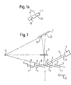
- the device shown in Fig. 1 comprises a light emitting unit 1, a Monitoring area 2, through which there are several overlapping ones Newspapers 7 move in the direction of an arrow 12, an optical one Unit 3 and a receiving unit 4.
- the light transmitter unit 1 consists of a light transmitter (not shown) and a beam splitter (not shown).
- the use of the light transmitter in Connection with the beam splitter has the advantage that when the Light intensity of the light transmitter, for example, due to aging keep the same light intensity for both light beams.
- the light emitting unit 1 sends two parallel ones Light rays 5, 6 in the surveillance area 2, which on the surface of the newspapers 7 from each other in the direction of movement of the newspapers 7 hit at a distance.
- the light emitting unit 1 sends two parallel ones Light rays 5, 6 in the surveillance area 2, which on the surface of the newspapers 7 from each other in the direction of movement of the newspapers 7 hit at a distance.
- the light rays 5, 6 are reflected on the surface of the newspaper 7 and via an optical unit 3 to a receiver 4 as beam images 10 shown.
- the optical unit 3 can have various optical elements, such as, for example Include lenses to reflect the reflected light rays onto the To reproduce the receiving unit 4 sharply. Scattered radiation that may occur, for example in connection with a glossy surface the newspapers 7 can occur is suppressed.
- the receiving unit 4, the optical unit 3 and through the flank areas 9 of the newspapers 7 defined main reflection level are according to the Scheimpflug condition is mutually arranged, d. H. cut it the image plane defined by the receiving unit, the optical plane Unit 3 defines the objective plane and the one defining the object plane Main reflection plane in a line which is perpendicular to the image plane in FIG. 1 stands and is therefore shown as point 11.
- the two parallel beams 5, 6 meet after its transmission from the light emitting unit 1 to the flank area 9 of a newspaper 7, are reflected there and by the optical Unit 3 focused on the receiving unit 4.
- the Receiver unit 4 beam images 10 shown, which are at a distance A from each other are spaced, as shown in Fig. la.
- the beam patterns 10 shift due to this of the falling flank area 9 on the receiving unit 4 (in this case to the right in Fig. 1), but their distance remains the same. From the direction and the size of the displacement of the beam images 10 the receiving unit 4 can in an evaluation unit on an incline of the flank area and thus on the direction of an edge jump be inferred.
- the beam path of the light beam 6 changes suddenly.
- the position of the light beam 5 is also changed Beam image 10 on the receiving unit 4 erratic, causing a new distance A 'results, as shown in Fig. 2a.
- This change in distance the beam image 10 on the receiving unit 4 shows an edge area 8 on. It is in the evaluation unit (not shown) when exceeded an edge detection signal of a predetermined threshold generated, which is fed to a counter (not shown). From the determination of the absolute positions of the beam images 10 on the Receiving unit 4 at this time can be in the evaluation unit (not shown) also determines the absolute height of the detected edge 8 become.
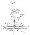
- Fig. 3 the same arrangement as in Figs. 1 and 2 is shown, however with the exception that here the two light beams 5, 6 are not parallel in the surveillance area 2 are sent.
- the beam guidance of the the two light beams 5, 6 are selected so that both light beams 5, 6 regardless of a level of movement 13, 14 of the newspapers 7 in relation to the position of the receiving unit 4 with the same imaging scale are mapped on the receiving unit 4, the level of movement 13, 14 of newspapers 7, for example, by the different Transport height of different conveyor belts is conditional.
- This beam guidance is in Fig. 3 for two different levels of movement 13, 14 of the newspapers 7 shown.
- Reference number 13 is a first level of movement shown for the newspapers 7, for example by a Conveyor belt height of a first conveyor belt is determined.
Landscapes
- Physics & Mathematics (AREA)
- Electromagnetism (AREA)
- Engineering & Computer Science (AREA)
- Computer Networks & Wireless Communication (AREA)
- General Physics & Mathematics (AREA)
- Radar, Positioning & Navigation (AREA)
- Remote Sensing (AREA)
- Length Measuring Devices By Optical Means (AREA)
- Geophysics And Detection Of Objects (AREA)
Abstract
Description
- Fig. 1
- eine schematische Darstellung einer erfindungsgemäß ausgebildeten Vorrichtung mit sich durch den Überwachungsbereich bewegenden Zeitungen,
- Fig. 1a
- eine Draufsicht auf eine Empfangseinheit mit darauf abgebildeten fokussierten Strahlbildern,
- Fig. 2
- die Vorrichtung gemäß Fig. 1 mit gegenüber Fig. 1 weiterbewegten Zeitungen,
- Fig. 2a
- die Draufsicht auf die Empfangseinheit mit entsprechend verschobenen Strahlbildern und
- Fig. 3
- die Vorrichtung gemäß Fig. 1 mit gegenüber den Fig. 1 und 2 geänderten Strahlverläufen der in den Überwachungsbereich ausgesandten Lichtstrahlen.
- 1
- Lichtsendeeinheit
- 2
- Überwachungsbereich
- 3
- optische Einheit
- 4
- Empfangseinheit
- 5
- Lichtstrahl
- 6
- Lichtstrahl
- 7
- Zeitungen
- 8
- Kantenbereich
- 9
- Flankenbereich
- 10
- Strahlbilder
- 10'
- Strahlbilder
- 11
- Schnittlinie (Scheimpflug)
- 12
- Pfeil
- 13
- Bewegungsniveau
- 14
- Bewegungsniveau
Claims (13)
- Verfahren zur Erfassung von Kantenbereichen von Objekten, insbesondere von sich überlappenden Zeitungen, bei demwenigstens zwei Lichtsignale (5, 6) in einen Überwachungsbereich (2) ausgesandt werden,die ausgesandten Lichtsignale (5, 6) von einem sich relativ zum Überwachungsbereich (2) bewegenden Objekt (7) reflektiert werden, zumindest ein Teil der reflektierten Lichtsignale (5, 6) als beabstandete Strahlbilder (10) auf eine ortsauflösende Empfangseinheit (4) abgebildet werden,der Abstand A zwischen den Strahlbildern (10) auf der Empfangseinheit (4) erfaßt wird,und bei Erfassung einer Abstandsänderung der Strahlbilder (10) um wenigstens einen vorbestimmten Schwellenwert ein Kantenerfassungssignal erzeugt wird.
- Verfahren nach Anspruch 1,
dadurch gekennzeichnet, daß die Lichtsignale (5, 6) in Form von Lichtstrahlen (5, 6) ausgesandt werden, wobei insbesondere die Lichtstrahlen (5, 6) auf der Oberfläche der Objekte (7) voneinander in Bewegungsrichtung der Objekte (7) beabstandet auftreffen. - Verfahren nach Anspruch 2,
dadurch gekennzeichnet,daß der Abstand der ausgesandten Lichtstrahlen (5, 6) und insbesondere der Abstand der auf die Oberfläche der Objekte (7) auftreffenden Lichtstrahlen (5, 6) änderbar ist und/oderdaß die Querschnittsfläche wenigstens eines ausgesandten Lichtstrahls (5, 6) und insbesondere die jeweilige Projektionsfläche der auf der Oberfläche der Objekte (7) auftreffenden Lichtstrahlen (5, 6) änderbar istund/oder daß der Einfallswinkel wenigstens eines der in den Überwachungsbereich (2) ausgesandten Lichtstrahlen (5, 6) änderbar ist. - Verfahren nach Anspruch 2 oder 3,
dadurch gekennzeichnet,daß die Lichtstrahlen (5, 6) parallel zueinander in den Überwachungsbereich (2) ausgesandt werden oderdaß die Lichtstrahlen (5, 6) nicht parallel zueinander in den Überwachungsbereich (2) ausgesandt werden, insbesondere daß die Lichtstrahlen (5, 6) unter einem solchen Winkel zueinander in den Überwachungsbereich (2) ausgesandt werden, daß durch Unterschiede im Bewegungsniveau (13, 14) der Objekte (7) auftretende unterschiedliche Abbildungsmaßstäbe ausgeglichen werden. - Verfahren nach einem der Ansprüche 2 bis 4,
dadurch gekennzeichnet, daß die reflektierten Lichtstrahlen (5, 6) auf der Empfangseinheit (4) scharf abgebildet werden. - Verfahren nach einem der vorhergehenden Ansprüche,
dadurch gekennzeichnet, daß die absoluten Positionen der Strahlbilder (10) auf der Empfangseinheit (4) bestimmt werden. - Verfahren nach Anspruch 6,
dadurch gekennzeichnet, daß unterhalb des vorbestimmten Schwellenwertes Änderungen der absoluten Positionen der Strahlbilder (10) erfaßt und aus diesen eine Richtung eines Kantensprunges der Objekte (7) bestimmt wird. - Verfahren nach Anspruch 6,
dadurch gekennzeichnet, daß oberhalb eines vorbestimmten Schwellenwerts aus den absoluten Positionen der Strahlbilder (10) eine Höhe der erfaßten Kante (8) bestimmt wird. - Verfahren nach einem der vorhergehenden Ansprüche,
dadurch gekennzeichnet, daß die erzeugten Kantenerfassungssignale gezählt werden und damit die Anzahl der erfaßten Kantenbereiche ermittelt wird und/oder daß der Überwachungsbereich (2) und die Objekte (7) relativ zueinander bewegt werden und insbesondere die Objekte (7) relativ zu dem örtlich fixierten Überwachungsbereich (2) bewegt werden. - Vorrichtung zur Erfassung von Kantenbereichen von Objekten, insbesondere von sich überlappenden Zeitungen, mit einer Lichtsendeeinheit (1) zum Aussenden von Lichtsignalen (5, 6) in einen Überwachungsbereich (2) und mit einer Empfangseinheit (4) zum Empfangen der an einem im Überwachungsbereich (2) angeordneten Objekt (7) reflektierten Lichtsignale (5, 6), insbesondere zur Durchführung des Verfahrens nach einem der vorhergehenden Ansprüche,
dadurch gekennzeichnet,daß die Lichtsendeeinheit (1) zum Aussenden von wenigstens zwei Lichtsignalen (5, 6) in den Überwachungsbereich (2) ausgebildet ist,daß im Strahlengang zwischen dem Überwachungsbereich (2) und der Empfangseinheit (4) eine optische Einheit (3) vorgesehen ist, durch die zumindest ein Teil der reflektierten Lichtsignale (5, 6) auf der Empfangseinheit (4) als beabstandete Strahlbilder (10) abbildbar sind, unddaß eine Auswerteeinheit zur Erfassung des Abstandes A zwischen den Strahlbildern (10) auf der Empfangseinheit (4) vorgesehen ist, wobei durch die Auswerteeinheit bei Erfassen einer Abstandsänderung der Strahlbilder (10) um mindestens einen vorgegebenen Schwellenwert ein Kantenerfassungssignal erzeugbar ist. - Vorrichtung nach Anspruch 10,
dadurch gekennzeichnet, daß die Lichtsendeeinheit (1) zum Aussenden der Lichtsignale (5, 6) in Form von Lichtstrahlen (5, 6) ausgebildet ist. - Vorrichtung nach Anspruch 10 oder 11,
dadurch gekennzeichnet,daß die Lichtsendeeinheit (1) zum Aussenden der Lichtsignale (5, 6) wenigstens zwei getrennte Lichtsender aufweist oderdaß die Lichtsendeeinheit (1) zum Aussenden der Lichtsignale (5, 6) einen einzelnen Lichtsender insbesondere in Verbindung mit einem Strahlteiler aufweist. - Vorrichtung nach einem der Ansprüche 10 bis 12,
dadurch gekennzeichnet, daß die Empfangseinheit (4), die optische Einheit (3) und die durch die sich durch den Überwachungsbereich (2) bewegenden Objekte (7) definierte Hauptreflexionsebene gemäß der Scheimpflug-Bedingung zueinander angeordnet sind, d. h. daß sich die durch die Empfangseinheit (4) definierte Bildebene, die durch die optische Einheit (3) definierte Objektivebene und die die Objektebene definierende Hauptreflexionsebene in einer Linie (11) schneiden, und/oder daß die Auswerteeinheit mit einer Zählvorrichtung zum Zählen der von der Auswerteeinheit erzeugten Kantenerfassungssignale verbunden ist.
Applications Claiming Priority (2)
| Application Number | Priority Date | Filing Date | Title |
|---|---|---|---|
| DE10012138 | 2000-03-13 | ||
| DE2000112138 DE10012138B4 (de) | 2000-03-13 | 2000-03-13 | Verfahren und Vorrichtung zur Erfassung von Kantenbereichen von Objekten |
Publications (2)
| Publication Number | Publication Date |
|---|---|
| EP1134594A1 true EP1134594A1 (de) | 2001-09-19 |
| EP1134594B1 EP1134594B1 (de) | 2013-11-20 |
Family
ID=7634517
Family Applications (1)
| Application Number | Title | Priority Date | Filing Date |
|---|---|---|---|
| EP01102343.9A Expired - Lifetime EP1134594B1 (de) | 2000-03-13 | 2001-02-01 | Verfahren und Vorrichtung zur Erfassung von Kantenbereichen von Objekten |
Country Status (2)
| Country | Link |
|---|---|
| EP (1) | EP1134594B1 (de) |
| DE (1) | DE10012138B4 (de) |
Cited By (3)
| Publication number | Priority date | Publication date | Assignee | Title |
|---|---|---|---|---|
| EP1429155A1 (de) * | 2002-12-12 | 2004-06-16 | Siemens Aktiengesellschaft | Verfahren zur Messung des Abstands eines an einer Referenzfläche vorbei gefürhrten Bauteils und Durchführung des Verfahrens |
| WO2008119192A1 (de) | 2007-04-03 | 2008-10-09 | Ferag Ag | Vorrichtung und verfahren zum zählen und erkennen von flächigen produkten |
| US7489425B2 (en) | 2004-03-15 | 2009-02-10 | Heidelberger Druckmaschinen Ag | Method for controlling an operating process of a printing machine |
Families Citing this family (1)
| Publication number | Priority date | Publication date | Assignee | Title |
|---|---|---|---|---|
| DE102005007993B4 (de) * | 2004-03-15 | 2015-12-24 | Heidelberger Druckmaschinen Ag | Verfahren zum Steuern eines Betriebsvorganges an einer drucktechnischen Maschine |
Citations (5)
| Publication number | Priority date | Publication date | Assignee | Title |
|---|---|---|---|---|
| US4659922A (en) * | 1985-02-19 | 1987-04-21 | Eaton Corporation | Optical sensor device for detecting the presence of an object |
| US4697921A (en) * | 1983-01-13 | 1987-10-06 | Amberg Messtechnik Ag | Device for detecting a relative change in distance between two measuring points, and its use |
| US4755662A (en) * | 1983-04-28 | 1988-07-05 | Canon Kabushiki Kaisha | Automatic focus detecting device |
| US4791759A (en) * | 1987-03-23 | 1988-12-20 | Daisyo Seiki Kabushiki Kaisha | Grinding wheel position detecting means for surface grinding machine |
| US5936229A (en) * | 1996-04-02 | 1999-08-10 | Trw Inc. | Tracking means for distant ballistic missile targets comprising means for tracking largest radius of curvature |
Family Cites Families (7)
| Publication number | Priority date | Publication date | Assignee | Title |
|---|---|---|---|---|
| US4666303A (en) * | 1983-07-11 | 1987-05-19 | Diffracto Ltd. | Electro-optical gap and flushness sensors |
| GB8410943D0 (en) * | 1984-04-28 | 1984-06-06 | Quantity & Time Menagem Syst | Object counting apparatus |
| DE3915857A1 (de) * | 1989-05-16 | 1990-12-13 | Bvs Gmbh | Vorrichtung zum zaehlen von produkten |
| DE3919917A1 (de) * | 1989-06-19 | 1991-01-03 | Pepperl & Fuchs | Optischer sensor fuer die identifizierung eines koerpers |
| GB9115745D0 (en) * | 1991-07-20 | 1991-09-04 | Longdin & Browning Surveys Lim | Method and apparatus for dimensional measurement |
| JPH05107032A (ja) * | 1991-10-16 | 1993-04-27 | Matsushita Electric Ind Co Ltd | 実装基板外観検査方法 |
| DE19532767C2 (de) * | 1995-09-05 | 2000-12-28 | Fraunhofer Ges Forschung | Triangulationsverfahren |
-
2000
- 2000-03-13 DE DE2000112138 patent/DE10012138B4/de not_active Expired - Fee Related
-
2001
- 2001-02-01 EP EP01102343.9A patent/EP1134594B1/de not_active Expired - Lifetime
Patent Citations (5)
| Publication number | Priority date | Publication date | Assignee | Title |
|---|---|---|---|---|
| US4697921A (en) * | 1983-01-13 | 1987-10-06 | Amberg Messtechnik Ag | Device for detecting a relative change in distance between two measuring points, and its use |
| US4755662A (en) * | 1983-04-28 | 1988-07-05 | Canon Kabushiki Kaisha | Automatic focus detecting device |
| US4659922A (en) * | 1985-02-19 | 1987-04-21 | Eaton Corporation | Optical sensor device for detecting the presence of an object |
| US4791759A (en) * | 1987-03-23 | 1988-12-20 | Daisyo Seiki Kabushiki Kaisha | Grinding wheel position detecting means for surface grinding machine |
| US5936229A (en) * | 1996-04-02 | 1999-08-10 | Trw Inc. | Tracking means for distant ballistic missile targets comprising means for tracking largest radius of curvature |
Cited By (4)
| Publication number | Priority date | Publication date | Assignee | Title |
|---|---|---|---|---|
| EP1429155A1 (de) * | 2002-12-12 | 2004-06-16 | Siemens Aktiengesellschaft | Verfahren zur Messung des Abstands eines an einer Referenzfläche vorbei gefürhrten Bauteils und Durchführung des Verfahrens |
| US7489425B2 (en) | 2004-03-15 | 2009-02-10 | Heidelberger Druckmaschinen Ag | Method for controlling an operating process of a printing machine |
| WO2008119192A1 (de) | 2007-04-03 | 2008-10-09 | Ferag Ag | Vorrichtung und verfahren zum zählen und erkennen von flächigen produkten |
| US8324558B2 (en) | 2007-04-03 | 2012-12-04 | Ferag Ag | Device and method for counting and detecting flat products |
Also Published As
| Publication number | Publication date |
|---|---|
| DE10012138B4 (de) | 2010-02-25 |
| DE10012138A1 (de) | 2001-09-20 |
| EP1134594B1 (de) | 2013-11-20 |
Similar Documents
| Publication | Publication Date | Title |
|---|---|---|
| DE2602001C3 (de) | Vorrichtung zur Überprüfung einer bearbeiteten Oberfläche eines Werkstucks | |
| EP1057727B1 (de) | Verfahren und Vorrichtung zum Prüfen von Zigarettenköpfen | |
| DE2256736A1 (de) | Verfahren zur automatischen oberflaechenprofilmessung und vorrichtung zur durchfuehrung des verfahrens | |
| EP2093173B1 (de) | Vorrichtung und Verfahren zur Detektion von Orientierungsmerkmalen auf einer Materialbahn | |
| DE102007004632A1 (de) | Verfahren zur Erfassung eines Gegenstands und optoelektronische Vorrichtung | |
| DE2713844C3 (de) | Vorrichtung zum Erkennen der Wertigkeit von Münzen o.dgl. Gegenstände | |
| DE102008039025B4 (de) | Verfahren zum berührungslosen Messen der Geschwindigkeit und/oder der Länge eines in Längsrichtung bewegten Strangs, insbesondere eines Kabels | |
| DE102004010566A1 (de) | Tastkopf für ein Koordinatenmessgerät | |
| DE19914962C2 (de) | Optoelektronische Vorrichtung | |
| EP1204845B1 (de) | Verfahren und vorrichtung zum erfassen eines biegewinkels an einem werkstück | |
| DE4304815A1 (de) | Optischer Sensor | |
| EP1623943A1 (de) | Vorrichtung und Verfahren zur Erfassung eines Merkmals einer laufenden Materialbahn | |
| EP1134594B1 (de) | Verfahren und Vorrichtung zur Erfassung von Kantenbereichen von Objekten | |
| DE3522809C2 (de) | ||
| EP0463566B2 (de) | Verfahren und Vorrichtung zur Trefferauswertung von Schiessscheiben | |
| DE2312029C3 (de) | ||
| CH637777A5 (de) | Lesevorrichtung fuer an einem gegenstand angebrachte farbmarken. | |
| EP1473540B1 (de) | Verfahren zur Bestimmung des Niveaus mehrerer Messpunkte sowie Anordnung dafür | |
| AT391027B (de) | Verfahren zum vermessen der kanten eines holzes im laengstransport und vorrichtung hierfuer | |
| DE2810192A1 (de) | Verfahren zur ueberwachung der abmessungen eines gegenstandes | |
| EP1136787B1 (de) | Objektabbildung mit Abstandskompensation ( Grösse, Farbe ) | |
| DE2251915A1 (de) | Vorrichtung zum feststellen von flekken oder fehlern in einer oberflaeche | |
| DE2809878A1 (de) | Verfahren zur bestimmung der abmessungen eines gegenstandes | |
| DE10133854A1 (de) | Münzprüfvorrichtung und Verfahren zur Münzprüfung | |
| CH695628A5 (de) | Messvorrichtung für Betonstabstähle. |
Legal Events
| Date | Code | Title | Description |
|---|---|---|---|
| PUAI | Public reference made under article 153(3) epc to a published international application that has entered the european phase |
Free format text: ORIGINAL CODE: 0009012 |
|
| AK | Designated contracting states |
Kind code of ref document: A1 Designated state(s): AT BE CH CY DE DK ES FI FR GB GR IE IT LI LU MC NL PT SE TR |
|
| AX | Request for extension of the european patent |
Free format text: AL;LT;LV;MK;RO;SI |
|
| 17P | Request for examination filed |
Effective date: 20011120 |
|
| AKX | Designation fees paid |
Free format text: AT BE CH CY DE DK ES FI FR GB GR IE IT LI LU MC NL PT SE TR |
|
| 17Q | First examination report despatched |
Effective date: 20041222 |
|
| RAP1 | Party data changed (applicant data changed or rights of an application transferred) |
Owner name: SICK AG |
|
| GRAP | Despatch of communication of intention to grant a patent |
Free format text: ORIGINAL CODE: EPIDOSNIGR1 |
|
| INTG | Intention to grant announced |
Effective date: 20130607 |
|
| GRAS | Grant fee paid |
Free format text: ORIGINAL CODE: EPIDOSNIGR3 |
|
| GRAA | (expected) grant |
Free format text: ORIGINAL CODE: 0009210 |
|
| AK | Designated contracting states |
Kind code of ref document: B1 Designated state(s): AT BE CH CY DE DK ES FI FR GB GR IE IT LI LU MC NL PT SE TR |
|
| REG | Reference to a national code |
Ref country code: GB Ref legal event code: FG4D Free format text: NOT ENGLISH |
|
| REG | Reference to a national code |
Ref country code: CH Ref legal event code: EP |
|
| REG | Reference to a national code |
Ref country code: AT Ref legal event code: REF Ref document number: 641951 Country of ref document: AT Kind code of ref document: T Effective date: 20131215 |
|
| REG | Reference to a national code |
Ref country code: IE Ref legal event code: FG4D Free format text: LANGUAGE OF EP DOCUMENT: GERMAN |
|
| REG | Reference to a national code |
Ref country code: DE Ref legal event code: R096 Ref document number: 50116355 Country of ref document: DE Effective date: 20140109 |
|
| REG | Reference to a national code |
Ref country code: NL Ref legal event code: VDEP Effective date: 20131120 |
|
| PG25 | Lapsed in a contracting state [announced via postgrant information from national office to epo] |
Ref country code: NL Free format text: LAPSE BECAUSE OF FAILURE TO SUBMIT A TRANSLATION OF THE DESCRIPTION OR TO PAY THE FEE WITHIN THE PRESCRIBED TIME-LIMIT Effective date: 20131120 Ref country code: FI Free format text: LAPSE BECAUSE OF FAILURE TO SUBMIT A TRANSLATION OF THE DESCRIPTION OR TO PAY THE FEE WITHIN THE PRESCRIBED TIME-LIMIT Effective date: 20131120 Ref country code: SE Free format text: LAPSE BECAUSE OF FAILURE TO SUBMIT A TRANSLATION OF THE DESCRIPTION OR TO PAY THE FEE WITHIN THE PRESCRIBED TIME-LIMIT Effective date: 20131120 |
|
| PG25 | Lapsed in a contracting state [announced via postgrant information from national office to epo] |
Ref country code: ES Free format text: LAPSE BECAUSE OF FAILURE TO SUBMIT A TRANSLATION OF THE DESCRIPTION OR TO PAY THE FEE WITHIN THE PRESCRIBED TIME-LIMIT Effective date: 20131120 |
|
| PGFP | Annual fee paid to national office [announced via postgrant information from national office to epo] |
Ref country code: FR Payment date: 20140218 Year of fee payment: 14 |
|
| PG25 | Lapsed in a contracting state [announced via postgrant information from national office to epo] |
Ref country code: PT Free format text: LAPSE BECAUSE OF FAILURE TO SUBMIT A TRANSLATION OF THE DESCRIPTION OR TO PAY THE FEE WITHIN THE PRESCRIBED TIME-LIMIT Effective date: 20140320 |
|
| PGFP | Annual fee paid to national office [announced via postgrant information from national office to epo] |
Ref country code: GB Payment date: 20140220 Year of fee payment: 14 |
|
| REG | Reference to a national code |
Ref country code: DE Ref legal event code: R097 Ref document number: 50116355 Country of ref document: DE |
|
| BERE | Be: lapsed |
Owner name: SICK A.G. Effective date: 20140228 |
|
| PLBE | No opposition filed within time limit |
Free format text: ORIGINAL CODE: 0009261 |
|
| STAA | Information on the status of an ep patent application or granted ep patent |
Free format text: STATUS: NO OPPOSITION FILED WITHIN TIME LIMIT |
|
| PG25 | Lapsed in a contracting state [announced via postgrant information from national office to epo] |
Ref country code: LU Free format text: LAPSE BECAUSE OF FAILURE TO SUBMIT A TRANSLATION OF THE DESCRIPTION OR TO PAY THE FEE WITHIN THE PRESCRIBED TIME-LIMIT Effective date: 20140201 Ref country code: DK Free format text: LAPSE BECAUSE OF FAILURE TO SUBMIT A TRANSLATION OF THE DESCRIPTION OR TO PAY THE FEE WITHIN THE PRESCRIBED TIME-LIMIT Effective date: 20131120 Ref country code: MC Free format text: LAPSE BECAUSE OF FAILURE TO SUBMIT A TRANSLATION OF THE DESCRIPTION OR TO PAY THE FEE WITHIN THE PRESCRIBED TIME-LIMIT Effective date: 20131120 |
|
| 26N | No opposition filed |
Effective date: 20140821 |
|
| REG | Reference to a national code |
Ref country code: IE Ref legal event code: MM4A |
|
| REG | Reference to a national code |
Ref country code: DE Ref legal event code: R097 Ref document number: 50116355 Country of ref document: DE Effective date: 20140821 |
|
| PG25 | Lapsed in a contracting state [announced via postgrant information from national office to epo] |
Ref country code: IE Free format text: LAPSE BECAUSE OF NON-PAYMENT OF DUE FEES Effective date: 20140201 Ref country code: BE Free format text: LAPSE BECAUSE OF NON-PAYMENT OF DUE FEES Effective date: 20140228 |
|
| REG | Reference to a national code |
Ref country code: AT Ref legal event code: MM01 Ref document number: 641951 Country of ref document: AT Kind code of ref document: T Effective date: 20140201 |
|
| PG25 | Lapsed in a contracting state [announced via postgrant information from national office to epo] |
Ref country code: AT Free format text: LAPSE BECAUSE OF NON-PAYMENT OF DUE FEES Effective date: 20140201 |
|
| GBPC | Gb: european patent ceased through non-payment of renewal fee |
Effective date: 20150201 |
|
| REG | Reference to a national code |
Ref country code: FR Ref legal event code: ST Effective date: 20151030 |
|
| PG25 | Lapsed in a contracting state [announced via postgrant information from national office to epo] |
Ref country code: GB Free format text: LAPSE BECAUSE OF NON-PAYMENT OF DUE FEES Effective date: 20150201 |
|
| PG25 | Lapsed in a contracting state [announced via postgrant information from national office to epo] |
Ref country code: FR Free format text: LAPSE BECAUSE OF NON-PAYMENT OF DUE FEES Effective date: 20150302 |
|
| PGFP | Annual fee paid to national office [announced via postgrant information from national office to epo] |
Ref country code: CH Payment date: 20160222 Year of fee payment: 16 |
|
| PG25 | Lapsed in a contracting state [announced via postgrant information from national office to epo] |
Ref country code: CY Free format text: LAPSE BECAUSE OF FAILURE TO SUBMIT A TRANSLATION OF THE DESCRIPTION OR TO PAY THE FEE WITHIN THE PRESCRIBED TIME-LIMIT Effective date: 20131120 Ref country code: GR Free format text: LAPSE BECAUSE OF FAILURE TO SUBMIT A TRANSLATION OF THE DESCRIPTION OR TO PAY THE FEE WITHIN THE PRESCRIBED TIME-LIMIT Effective date: 20140221 |
|
| PG25 | Lapsed in a contracting state [announced via postgrant information from national office to epo] |
Ref country code: TR Free format text: LAPSE BECAUSE OF FAILURE TO SUBMIT A TRANSLATION OF THE DESCRIPTION OR TO PAY THE FEE WITHIN THE PRESCRIBED TIME-LIMIT Effective date: 20131120 |
|
| PGFP | Annual fee paid to national office [announced via postgrant information from national office to epo] |
Ref country code: IT Payment date: 20170217 Year of fee payment: 17 |
|
| REG | Reference to a national code |
Ref country code: CH Ref legal event code: PL |
|
| PG25 | Lapsed in a contracting state [announced via postgrant information from national office to epo] |
Ref country code: LI Free format text: LAPSE BECAUSE OF NON-PAYMENT OF DUE FEES Effective date: 20170228 Ref country code: CH Free format text: LAPSE BECAUSE OF NON-PAYMENT OF DUE FEES Effective date: 20170228 |
|
| PGFP | Annual fee paid to national office [announced via postgrant information from national office to epo] |
Ref country code: DE Payment date: 20180221 Year of fee payment: 18 |
|
| PG25 | Lapsed in a contracting state [announced via postgrant information from national office to epo] |
Ref country code: IT Free format text: LAPSE BECAUSE OF NON-PAYMENT OF DUE FEES Effective date: 20180201 |
|
| REG | Reference to a national code |
Ref country code: DE Ref legal event code: R119 Ref document number: 50116355 Country of ref document: DE |
|
| PG25 | Lapsed in a contracting state [announced via postgrant information from national office to epo] |
Ref country code: DE Free format text: LAPSE BECAUSE OF NON-PAYMENT OF DUE FEES Effective date: 20190903 |