EP1134538A2 - Markierelement mit einer Vorrichtung zum Verlegen gestapelter Markierelemente - Google Patents
Markierelement mit einer Vorrichtung zum Verlegen gestapelter Markierelemente Download PDFInfo
- Publication number
- EP1134538A2 EP1134538A2 EP01101224A EP01101224A EP1134538A2 EP 1134538 A2 EP1134538 A2 EP 1134538A2 EP 01101224 A EP01101224 A EP 01101224A EP 01101224 A EP01101224 A EP 01101224A EP 1134538 A2 EP1134538 A2 EP 1134538A2
- Authority
- EP
- European Patent Office
- Prior art keywords
- marking
- marking element
- spring
- laying
- element according
- Prior art date
- Legal status (The legal status is an assumption and is not a legal conclusion. Google has not performed a legal analysis and makes no representation as to the accuracy of the status listed.)
- Granted
Links
Images



Classifications
-
- F—MECHANICAL ENGINEERING; LIGHTING; HEATING; WEAPONS; BLASTING
- F41—WEAPONS
- F41H—ARMOUR; ARMOURED TURRETS; ARMOURED OR ARMED VEHICLES; MEANS OF ATTACK OR DEFENCE, e.g. CAMOUFLAGE, IN GENERAL
- F41H11/00—Defence installations; Defence devices
- F41H11/12—Means for clearing land minefields; Systems specially adapted for detection of landmines
-
- E—FIXED CONSTRUCTIONS
- E01—CONSTRUCTION OF ROADS, RAILWAYS, OR BRIDGES
- E01F—ADDITIONAL WORK, SUCH AS EQUIPPING ROADS OR THE CONSTRUCTION OF PLATFORMS, HELICOPTER LANDING STAGES, SIGNS, SNOW FENCES, OR THE LIKE
- E01F9/00—Arrangement of road signs or traffic signals; Arrangements for enforcing caution
- E01F9/60—Upright bodies, e.g. marker posts or bollards; Supports for road signs
- E01F9/623—Upright bodies, e.g. marker posts or bollards; Supports for road signs characterised by form or by structural features, e.g. for enabling displacement or deflection
- E01F9/654—Upright bodies, e.g. marker posts or bollards; Supports for road signs characterised by form or by structural features, e.g. for enabling displacement or deflection in the form of three-dimensional [3D] bodies, e.g. cones; capable of assuming 3D form, e.g. by inflation or erection to form a geometric body
-
- E—FIXED CONSTRUCTIONS
- E01—CONSTRUCTION OF ROADS, RAILWAYS, OR BRIDGES
- E01F—ADDITIONAL WORK, SUCH AS EQUIPPING ROADS OR THE CONSTRUCTION OF PLATFORMS, HELICOPTER LANDING STAGES, SIGNS, SNOW FENCES, OR THE LIKE
- E01F9/00—Arrangement of road signs or traffic signals; Arrangements for enforcing caution
- E01F9/60—Upright bodies, e.g. marker posts or bollards; Supports for road signs
- E01F9/688—Free-standing bodies
-
- E—FIXED CONSTRUCTIONS
- E01—CONSTRUCTION OF ROADS, RAILWAYS, OR BRIDGES
- E01F—ADDITIONAL WORK, SUCH AS EQUIPPING ROADS OR THE CONSTRUCTION OF PLATFORMS, HELICOPTER LANDING STAGES, SIGNS, SNOW FENCES, OR THE LIKE
- E01F9/00—Arrangement of road signs or traffic signals; Arrangements for enforcing caution
- E01F9/60—Upright bodies, e.g. marker posts or bollards; Supports for road signs
- E01F9/70—Storing, transporting, placing or retrieving portable devices
Definitions
- the invention relates to a marking element with a device for laying stacked Marking elements from a self-propelled land vehicle on one Terrain.
- mine-free alleys are cleared using generally vehicle-based clearing devices.
- the "Pathfinder" system uses flagpoles that pneumatically shot into the ground from a laying device. Fundamental disadvantages are that the system on hard ground, especially on asphalt roads and the pneumatic performance must be precisely matched to the properties of the substrate. With stony There is a danger that the flagpoles will penetrate safely is not guaranteed. The long-term stability of the marking is limited, in particular ground vibrations caused by wind and vehicles can cause the flagpoles to tilt and fall. The packing volume is limited if systems based on this operating principle with combat vehicles should be used.
- Color marking systems have small building designs; Color markings on the ground, however, are difficult to see from a vehicle; you can are covered by snow, rain and mud and are always included damp substrates can only be used to a limited extent.
- Existing building designs show that installation on a vehicle is possible in a simple manner. The The marking principle is used for marking mine lanes for driving through provided by vehicles are considered unsuitable.
- Another disadvantage of this known marking element is when the laying process a marking element due to unfavorable leaving behavior and uneven surface falls to the side, no possibility is provided that the element can automatically stand upright again. Furthermore is also no delay in the activation of the marking stick when exiting the Laying device provided. This can disrupt the mechanism come through interaction with the laying system.
- This well-known laying system is also for side use - projecting beyond the curb chain not suitable because the vertical projection surface through the base plate and the length of the marking stick is determined. Since the marking elements are used from the side must be at least 1000 mm high is a workable construction not possible according to the principle presented.
- marking elements with a device to provide for laying stacked marking elements by the marking elements can be positioned so securely on the left and right at the edge of the cleared alley can that the location and the course of the cleared alley clearly through People and vehicle crew regardless of the weather, underground and ground conditions are recognized by both the vehicle and people can.
- the invention is based on the knowledge that, on the one hand, as many marking elements as possible to be able to accommodate in a laying device and on the other hand marking elements with a height of 1,300 mm to be realized in such a way that it is clear can be seen from every aspect angle at distances greater than 20 m. Is to it is necessary to make the marking elements activatable.
- the marking elements are kept to a minimum in the transport state Volume packed in the form of a circular disc, which after being removed from the laying device automatically activate to their operational size.
- the sales and activation process does not lead to any misalignment of the marking element on the surface to the selected position.
- the solution principle according to the invention enables, before and during the laying process any number of marking elements up to the maximum capacity of the laying device reload.
- the marking elements are activated by the Energy of preloaded springs.
- the marking element according to the invention consists of an activated one in the marking state Spring preferably a conical spring or one or more Spring bars, the height of which depends solely on the wire cross-section Standing quality of the activated spring is limited and the volume of the marking element in the packaged state - with spring not activated - optimally used.
- the marking element is rotationally symmetrical both when packaged and when activated trained, i.e. no parts protrude sideways from the base plate. For the above reasons, optimal use of the installation space is the Laying device given by the flat and disc-shaped shape of the Marking element can be executed as a tube in the folded state and which the marking elements fill in a large number without loss of space.
- the marking element also advantageously has, in addition to a base plate at least one, preferably three support surfaces, which are in the transport state Fall out of the laying device - via the conical spring or bar spring trained spring element are folded and hold them in the tensioned state. When activated, the support surfaces release the spring element and fold into the plane the base plate via its hinge springs.
- a toothing of the marking element with the base also supports at.
- the marking element is therefore on all surfaces, such as sandy soils, muddy clay, snow, icy surfaces, gravel and gravel paths, Asphalt roads and forest paths, can be used, whereby the structure of the underground, such as stones, vegetation, bumps etc., to no functional impairment leads.
- the marking element also advantageously has a locking system Inhibitor that in the transport state the support surfaces that the conical spring or holds the spring bar or bars, locked and only when the marking element releases from the laying system. Only approx. 1.5 seconds after the laying process the inhibitor releases the support surfaces and thus the spring element.
- the advantage consists in the fact that the marking element is upside down even when it hits the floor rotated by the unfolding support surfaces of proven dimensions. Furthermore, the time delay causes there to be no hindrance to activation through the laying system, which after 1.5 seconds, for example with a Tank drove about 1.5 m further.
- the marking elements are visually recognizable due to their stable construction, supported by ropes with a height above the ground of 1,300 mm and an average diameter of 100 mm.
- the visible structure consists of a conical spring or one or more rod springs. Visibility is further increased by light strips integrated in the spring elements.
- an active lighting element advantageously an LED, can be integrated at the tip of the marking element and an electrical capacitive energy store in conjunction with a micro-wind generator in the bottom of the marking element without restricting the design advantages in terms of volume and handling .
- the integration of light sticks (cold chemical light) is also possible in principle. This equipment enables the marking elements to be seen day and night from a distance of 20 m from every aspect angle.
- the energy supply required for the electrical lighting element can be capacitive and / or with a generator and / or solar cells, in order to ensure a shelf life of at least 20 years and perfect functioning in the temperature range from minus 30 degrees Celsius to plus 50 degrees Celsius.
- the electrical lighting element directly from the electrical energy store for approximately 6 hours directly after the installation the latter is charged with electrical energy by the installation device immediately before the installation.
- the optical coloring of the marking elements, as well as the light of the active lighting, is selected in such a way that the left edge of the alley is marked, for example by red elements, the right edge by green elements.
- the marking element also ensures that it can be recognized, even in the event of rain and snow, up to an overlap height of at least 60 cm thanks to its large contact height.
- the marking elements are secured in the tubular state from above in the transport state Laying device loaded.
- the marking elements are to be stacked, for example packed 10 pieces each.
- These packing units are very space-saving, because the design of the marking element as an annular disc, for example, only one respective height of 17 mm height, 250 mm outer diameter and an inner diameter of 50 mm.
- the soldier is responsible for the charging process a loading aid in the central hole of the stack.
- claws that pushed in and out at the end of the handlebar by pressing a lever on the handle the stack with the marking elements can be excluded and also be discontinued.
- There is a fuse pin in each stack the is attached to the loading aid using a short rope. Then the stack can be placed in the Laying device can be used from above. When the handlebar is released, the The fuse pins are automatically pulled, the marking elements are then over a bandage is secured in the pipe of the laying device.
- a marking element is laid by rotating a two-stage Gear, an exemplary first release device on the bottom of the laying device, through which the marking element simply falls out.
- the construction of the laying device with A pipe length of, for example, 1,250 mm has a filling capacity of approx. 70 marking loads. By placing, for example, 200 mm high tube modules the capacity can be increased as required.
- the mechanism of the laying device allows the marking elements to be set down easily up to vehicle speeds of 12 km / h.
- the system does not require any special safety measures for transport, attachment or operation. No pyrotechnic elements are used.
- the control unit is electrical with the vehicle only connected to the electrical system.
- the average power requirement is less than 5 amps.
- the control unit can be accommodated by the driver or the commander.
- the laying device has a non-contact speedometer (Sensor) with the data of the distance traveled by the vehicle in the control unit is measured. This allows the distance between the marking elements on the control unit be set, the speed is automatically maintained regardless of the speed becomes.
- Sensor non-contact speedometer
- Attaching the system to a vehicle is extremely easy. It's just that two laying devices at the rear of the vehicle left and right by means of Attach adapter, the cable connections between a laying device and the control unit between the two laying devices as well between the control unit and the electrical system.
- the marking elements are again after use usable.
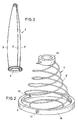
- FIG. 1 illustrates the marking element 1 in an active position.
- the marking element is based on a circular base plate 9 1 formed by a conical spring 8, for example in the operative position can have a height of 1,300 mm.
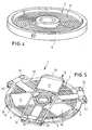
- FIGS. 2 to 4 show a further embodiment variant of the spring element 5 shown, which here consists for example of 3 spring bars 8 '.
- spring bars 8 ' for example wire elements
- a ring 36 which is located on the base plate 9, attached.
- the attachment is made so that the wire element is guided inside through a bore 37 in the ring and rotatable in the bore is.
- the leadership of the wire element from the inside through the ring causes that Wire element presses elastically against the ring.
- a vertical groove 38 is introduced with the width of the wire element, which causes the wire element in the vertical position through Elasticity presses into the groove and stabilizes in the vertical position.
- the wire elements 8 ' are also brought together on the upper side in an advantageously small ring 39 with the same fastening principle as on the base side.
- the elasticity of the 3 wire elements together with the type of attachment ensure high stability in the activated state.
- the wire elements 8 ' are screwed in via the upper ring 39.
- This rotation causes the wire elements on the bushings in the rings to be pushed out of the groove, thus turning sideways in the bore and lying against the inner wall of the ring.
- the elasticity of the wire elements causes the wire elements 8 'to endeavor to return to the vertical position.
- the wire elements, when placed in the annulus 36, are held by the support surfaces.
- the circular ring is advantageously somewhat conical on the inside, so that the elasticity of the wire elements slides out of the ring after the support surfaces are opened and straightens them up immediately.
- the as Spring element 5 designed conical compression spring 8 or at least one spring bar 8 'held by three superimposed support elements 6, which have a respective Torsion spring 12 on the base plate 9 in an orientation of 120 degrees to each other are attached.
- the top bracket 10 contains an inhibitor 13 for releasing a fuse a predetermined time for the bow 10 to spread and unfold or erect of the spring element 5.
- the escapement 13 also forms a mechanical bandage protection with approx. 1.5 seconds release time.
- the support plates 11 act as inhibitors and prevent the wire bracket from penetrating into soft ground or snow. For example, 8 light strips 14 are in the conical spring for better Added recognizability.
- the spring elements 5 can Spring steel wire or plastic, so that they are in the active state have a high stability.
- the conical spring 8 is spread with each Bracket 10 and the base plate 9 additionally via stabilizing ropes 15 connected.
- the base plate 9 has an integrated power supply for an active flashing LED 17 connected via thin-walled power cables 27, wherein the blinking LED 17 is mounted on the head of the conical spring 8 and the power cable 27 can be a fine single-core power cable that is inserted into the conical spring.
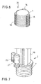
- FIG. 6 illustrates that the non-activated marking element 1 in the transport state, whereby for easier handling the marking element 1 as a stack 28 with 10 Marking elements 1 with a total height of 180 mm, for example, secure against rotation packed and loaded with clamps 16. On the loading process in detail in the description of Figures 9 to 12.
- Figures 7 and 8 illustrate in detail the structure of the laying device 2, which contains a marking element magazine 18 as the basic structure.
- This magazine contains 18 guide grooves 19 in the area of the torsion spring 12 of the Marking element 1 arranged projections 20 of the base plate 2 engage.
- a flange 29 At the The lower end of the tubular magazine 18 is a flange 29 for receiving the Laying device 2 arranged for laying the marking elements.
- the top one The end of the magazine 18 forms a closure cover, which is by means of tension locks 30 is attached to the circumference of the magazine ( Figure 12).
- the motor 21 drives a via a gear 31 between the magazine-fixed flange 29 and a magazine-fixed one underneath it Plate 24 arranged gear 22.
- Both the upper flange 29 like that lower plate 24 and the gear 22 are with guide grooves 19, 19 'and 19 " equipped, which runs according to the grooves 19 of the marking element magazine 18 are.
- the guide grooves 19 "of the lower plate 24 are towards the guide grooves 19 of the magazine arranged offset, thereby releasing the marking element 1 in the correct orientation only by rotating the gear 22 from the position of the magazine guide grooves 19 into the position of the guide grooves 19 "of Plate 24 can be done.
- the following marking element is placed during the release on the gear 22, which only after turning back into the position of the grooves 19 of the magazine 18 can hold the next marking element and through Repeat the turning process in the position 19 "of the lower plate 24 the other Laying process continues. So essentially the gear 22 takes over Transport of the individual marking elements 1 from the guide groove 19 of the magazine 18 to a delivery opening twisted by 60% on the lower plate 24 in the housing base 24th
- the laying device 2 is also with an autonomous speed sensor 25 equipped the contactlessly above the terrain 4 the speed measures.
- the signal is from a computer unit of the operating device, not shown converted into distance by time integration.
- Figures 9 and 10 illustrate that the laying device 2 over a Swivel bracket 32 is connected to the vehicle rear left and right.
- the lateral swivel range allows the marking width to be set in the area from 2.5 to 5 m.
- the swivel bracket 32 is a cross-sectional assembly for designed for use on different vehicles.
- the mechanical Recording for the laying device executed so that the ground clearance of the laying device 2 can be adapted to vehicle 3 and terrain 4.
- a mechanical loading aid 26 is used (FIG. 11). With the help of this loading aid 26 can a packaging unit or module 28 ( Figures 6 and 12) with 10 marking elements be loaded at the same time. At the lower end of the loading aid 26 is a three-part claw 33, which is guided by a rod in the inner part a hand trap 34 can expand.
- the loading aid 26 is in the central bore of the marking elements 1 until it stops introduced. Subsequently, a rope is also shown in FIG Pin 35 of the marking elements 1 in an eyelet on the neck of the loading aid 26 mounted. By actuating the hand trap 34, the claws are expressed so that the marking element 1 can be lifted up.
- the marking elements 1 can then be inserted into the laying device 2 from above become.
- the loading aid 26 becomes the marking elements pulled out and at the same time pulled the pin.
- On the marking elements 1 can be removed from the laying device 2 in the same way be pulled out.
- the bandage is secured by the inserted loading aid 26 secured.
- the pin 35 After pulling out the marking elements 1 from the laying device 2, the pin 35 must then be reinserted into the marking elements 1 are pulled out of the marking elements 1 before the loading aid 26 becomes.
- the laying devices 2 are removed from the working position ( Figure 10) pivoted into the transport position ( Figure 9). In the transport position can be loaded via the rear of the vehicle.
- FIG. 12 also illustrates a further exemplary embodiment of a Laying device 200 with the modular magazine tubes containing marking elements 1 28 are connected via snap fasteners 30.
- This laying device 200 is connected to the vehicle via brackets 4, not shown.
- the loading of the marking elements 1 takes place here as follows:
- Additional magazine tubes 28 can be placed and loaded in the same way.
- the drive, not shown, of this laying system can be electromechanical, be carried out pneumatically or hydraulically.
- the drive opens or closes synchronously at least one, for example three retaining flaps 71.
- the clamping bolts 72 are over Clamping arms 73, the torsion springs (not shown) with the retaining flaps 71 are connected, biased so that the clamping of the next over this force Marking element 1 takes place.
- the following closing of the retaining flaps 71, the clamping arms 72 are relieved, so that the entire stack of marking elements 1 slips by a marker element height.
- This is also connected to the laying device 200 and can be driven automatically Release device 17 guarantees that the marking element 1 while driving controlled and oriented by its own weight for the laying process from the Release device 70 falls out.
Landscapes
- Engineering & Computer Science (AREA)
- Architecture (AREA)
- Civil Engineering (AREA)
- Structural Engineering (AREA)
- Physics & Mathematics (AREA)
- Geometry (AREA)
- General Engineering & Computer Science (AREA)
- Refuge Islands, Traffic Blockers, Or Guard Fence (AREA)
- Road Signs Or Road Markings (AREA)
Abstract
Description
Um das elektrische Leuchtelement direkt nach der Verlegung für annähernd 6 Stunden allein aus dem elektrischen Energiespeicher versorgen zu können, wird dieser unmittelbar vor der Verlegung durch die Verlegevorrichtung mit elektrischer Energie aufgeladen. Die optische Farbgebung der Markierelemente, sowie das Licht der aktiven Beleuchtung ist farblich so gewählt, daß jeweils der linke Rand der Gasse, z.B. durch rote Elemente, der rechte Rand durch grüne Elemente, markiert ist. Das Markierelement gewährleistet darüber hinaus durch ihre große Aufstandshöhe eine Erkennbarkeit auch bei Regen und Schneefall bis zu einer Überdeckungshöhe über Grund von mindestens 60 cm.
- Figur 1
- das Markierelement in Wirkposition in dreidimensionaler Darstellung;
- Figur 2
- als Federelemente des Markierelementes ausgebildete Federstäbe;
- Figur 3
- die in Figur 2 dargestellten Federstäbe in Wirkposition;
- Figur 4
- die in Figur 2 dargestellten Federstäbe in einem zusammengelegten Zustand vor Einnahme der Wirkposition;
- Figur 5
- das Markierelement in zusammengefaltetem Zustand vor Einnahme der Wirkposition;
- Figur 6
- eine dreidimensionale Ansicht eines aus zehn Markierelementen gestapelten Markierungsmodules;
- Figur 7
- eine dreidimensionale Ansicht eines ersten Ausführungsbeispiels der Verlegevorrichtung;
- Figur 8
- eine dreidimensionale Ansicht einer mit der Verlegevorrichtung verbundenen Freigabevorrichtung der Markierungselemente;
- Figur 9
- die Befestigung der Verlegevorrichtung am Heck eines Panzers in eingeschwenkter Beladeposition;
- Figur 10
- die Verlegevorrichtung in ausgeschwenkter Wirkposition während des Verlegevorganges;
- Figur 11
- eine Ladehilfe zum Beladen der Markierungsmodule;
- Figur 12
- eine Ansicht eines aus Markierungsmodulen zusammengesetzten Magazins mit einem 2. Ausführungsbeispiel der Verlegevorrichtung.
Die Elastizität der 3 Drahtelemente gewährleisten zusammen mit der Art der Befestigung eine hohe Stabilität im aktivierten Zustand.
Die Drahtelemente werden, wenn sie in den Kreisring 36 eingelegt wurden, durch die Stützflächen gehalten. Der Kreisring ist innen vorteilhafterweise etwas konisch ausgeführt, so daß die Drahtelemente nach Aufklappen der Stützflächen durch ihre Elastizität aus dem Ring nach oben herausrutschen und sofort aufrichten.
Claims (18)
- Markierelement (1) mit einer Vorrichtung (2;200) zum Verlegen gestapelter Markierelemente (1) von einem selbst angetriebenen Landfahrzeug (3) auf einem Gelände (4), gekennzeichnet durch folgende Merkmale:a) Das Markierelement (1) ist vor dem Verlegevorgang in einer Vielzahl zusammengefalteter Scheiben in der Verlegevorrichtung (2;200) angeordnet;b) mit der Verlegevorrichtung (2;200) ist eine automatische antreibbare Freigabevorrichtung (7;70) derart verbunden, daß das Markierelement (1) während der Fahrt kontrolliert und durch sein Eigengewicht für den Verlegevorgang aus der Freigabevorrichtung (7;70) herausfällt;c) das Markierelement (1) besteht aus wenigstens einem Federelement (5), das sich nach dem Verlegen durch Aktivierung selbsttätig in seine Wirkposition entfaltet und dabei wenigstens ein angelenktes Stützelement (6) zur Aufrichtung und Stabilisierung des Markierelementes (1) ausbreitet.
- Markierelement nach Anspruch 1, dadurch gekennzeichnet, daß das Federelement (5) eine Kegelfeder (8) ist.
- Markierelement nach Anspruch 1, dadurch gekennzeichnet, daß das Federelement (5) wenigstens ein Federstab (8') ist.
- Markierelement nach einem der Ansprüche 1 bis 3, dadurch gekennzeichnet, daß wenigstens ein Stützelement (6) mit einer das Federelement (5) tragenden kreisförmigen Bodenplatte (9) gelenkartig verbunden ist und aus einem Bügel (10) besteht, der das Federelement (5) vor dem Verlegen in dem zusammengefalteten Zustand hält.
- Markierelement nach Anspruch 4, dadurch gekennzeichnet, daß der Bügel (6) aus Draht besteht und gegen Eindringen in beispielsweise weichem Boden Stützflächen, vorzugsweise Stützbleche (11) enthält.
- Markierelement nach einem der Ansprüche 1 bis 5, dadurch gekennzeichnet, daß das Federelement (5) im zusammengefalteten Zustand (Transportzustand) durch wenigstens einen über das zusammengefaltete Federelement (5) gelegten Bügel (10) gehalten ist, wobei der Bügel (10) über eine Drehfeder (12) an der Bodenplatte (9) befestigt ist.
- Markierelement nach Anspruch 6, dadurch gekennzeichnet, daß das Federelement (5) im zusammengefalteten Zustand (Transportzustand) durch 3 übereinander gelegte Bügel (10) gehalten ist, wobei die Bügel (10) über eine jeweilige Drehfeder (12) an der Bodenplatte (9) in einer Orientierung von 120 Grad zueinander befestigt sind.
- Markierelement nach Anspruch 6 und 7, dadurch gekennzeichnet, daß der oberste Bügel (10) ein Hemmwerk (13) zur Freigabe einer Sicherung nach einer vorgebbaren Zeit zur Ausbreitung der Bügel und Entfaltung bzw. Aufrichtung des Federelementes (5) enthält.
- Markierelement nach einem der Ansprüche 1 bis 8, dadurch gekennzeichnet, daß in die Kegelfeder (8) Leuchtbänder (14) zur besseren Erkennbarkeit eingefügt sind.
- Markierelement nach einem der Ansprüche 1 bis 9, dadurch gekennzeichent, daß die Kegelfeder (8) mit jedem ausgebreiteten Bügel (10) und der Bodenplatte (9) über stabilisierende Seile (15) verbunden ist.
- Markierelement nach einem der Ansprüche 1 bis 10, dadurch gekennzeichnet, daß das nicht aktive Markierelement (1) im Transportzustand mit Spannklammern (16) verdrehsicher in Stapel verpackt und ladbar ist.
- Markierelement nach einem der Ansprüche 1 bis 11, dadurch gekennzeichnet, daß die Bodenplatte (9) eine integrierte Stromversorgung für ein aktives Leuchtelement, vorteilhafterweise eine LED, (17) enthält.
- Markierelement nach einem der Ansprüche 1 bis 12, dadurch gekennzeichnet, daß für die Markierung einer Minengasse zwei Verlegevorrichtungen (2) im Heckbereich des Landfahrzeuges (3) links und rechts ausschwenkbar angeordnet sind.
- Markierelement nach einem der Ansprüche 1 bis 13, dadurch gekennzeichnet, daß die Verlegevorrichtung (2;200) ein rohrförmiges Markierelement-Magazin (18) enthält, das Führungsnuten (19) als Verdrehsicherung für die Markierelemente (1) enthält, wobei im Bereich der Drehfeder (12) des Markierelements (1) entsprechende Vorsprünge (20) der Bodenplatte (9) in die Führungsnuten (19) eingreifen.
- Markierelement nach einem der Ansprüche 1 bis 14, dadurch gekennzeichnet, daß die Freigabevorrichtung (7) ein durch einen Motor (21) antreibbares Zahnrad (22) enthält, das mit Führungsnuten (19') entsprechend den Nuten (19) des Markierelement ― Magazins (18) ausgestattet ist, und daß unterhalb des Zahnrades (22) eine magazinfeste Platte (24) angeordnet ist, deren lichter Querschnitt (23) ebenfalls den Außenkonturen des Markierelementes (1) entspricht, deren Führungsnuten (19") zu den Führungsnuten (19) des Magazins jedoch versetzt angeordnet sind, wodurch eine Freigabe des Markierelementes (1) in der richtigen Orientierung erst durch Drehung des Zahnrades (22) aus der Lage der Magazinführungsnuten (19) in die Lage der Führungsnuten (19") der Platte (24) erfolgt.
- Markierelement nach einem der Ansprüche 1 bis 14, dadurch gekennzeichnet, daß die Freigabevorrichtung (70) am unteren Ende elektromechanisch, pneumatisch oder hydraulisch antriebbare Rückhalteklappen (71) enthält, die aus einer Blockierstellung nach ihrer Aktivierung das Markierelement (1) für die Verlegung freigibt, jedoch gleichzeitig ein durch Federkraft über Klemmarme (73) vorspannbarer Klemmbolzen (72) das nachfolgende Markierelement (1) festklemmt.
- Markierelement nach einem der Ansprüche 1 bis 16, dadurch gekennzeichnet, daß die Verlegevorrichtung (2) mit einem die Geschwindigkeit berührungslos über dem Gelände (4) messenden Sensor (25) zur Ermittlung des Verlegeabstandes der Markierelemente (1) während der Fahrt ausgerüstet ist.
- Markierelement nach einem der Ansprüche 1 bis 17, gekennzeichnet durch eine Ladehilfe (26) zum Be- und Entladen des Magazins (18) mit zu Verpakkungseinheiten gestapelten Markierelementen (1).
Applications Claiming Priority (2)
| Application Number | Priority Date | Filing Date | Title |
|---|---|---|---|
| DE10011748 | 2000-03-13 | ||
| DE10011748A DE10011748C2 (de) | 2000-03-13 | 2000-03-13 | Markierelement und Vorrichtung zum Verlegen dieser Markierelemente |
Publications (3)
| Publication Number | Publication Date |
|---|---|
| EP1134538A2 true EP1134538A2 (de) | 2001-09-19 |
| EP1134538A3 EP1134538A3 (de) | 2002-05-02 |
| EP1134538B1 EP1134538B1 (de) | 2006-03-22 |
Family
ID=7634256
Family Applications (1)
| Application Number | Title | Priority Date | Filing Date |
|---|---|---|---|
| EP01101224A Expired - Lifetime EP1134538B1 (de) | 2000-03-13 | 2001-01-19 | Markierelement mit einer Vorrichtung zum Verlegen gestapelter Markierelemente |
Country Status (2)
| Country | Link |
|---|---|
| EP (1) | EP1134538B1 (de) |
| DE (2) | DE10011748C2 (de) |
Families Citing this family (1)
| Publication number | Priority date | Publication date | Assignee | Title |
|---|---|---|---|---|
| DE10153024B4 (de) * | 2001-10-26 | 2006-04-20 | Hans-Walter Mohr Gmbh | Vorrichtung zum Vereinzeln von plattenartigen Werkstücken |
Citations (1)
| Publication number | Priority date | Publication date | Assignee | Title |
|---|---|---|---|---|
| EP0226700B1 (de) | 1985-10-23 | 1989-06-07 | The State Of Israel, Ministry Of Defence, Israel Military Industries | An einem Landfahrzeug anzubringende Vorrichtung zum Legen von Markierungszeichen |
Family Cites Families (8)
| Publication number | Priority date | Publication date | Assignee | Title |
|---|---|---|---|---|
| US2192635A (en) * | 1937-04-30 | 1940-03-05 | James G Bricker | Flag support |
| FI58187C (fi) * | 1976-10-26 | 1980-12-10 | Salon Automyynti Oy | Foerfarande foer faellning av varningsmaerken pao vaegyta eller motsvarande och anordning foer genomfoerande av foerfarandet |
| GB2049767B (en) * | 1979-04-19 | 1983-02-16 | Warning Pyramids Ltd | Self-erecting road marker pyramid |
| GB8323079D0 (en) * | 1983-08-26 | 1983-09-28 | Solicitor For Affairs Of Her M | Collapsible hazard warning marker |
| US4552089A (en) * | 1983-10-14 | 1985-11-12 | Mahoney Thomas P | Road warning emergency system and method of utilizing same |
| FR2556378B1 (fr) * | 1983-12-13 | 1986-05-23 | Michit Emile | Procede et machine pour ramasser, stocker et poser mecaniquement des balises de signalisation routiere coniques et creuses |
| US4901644A (en) * | 1989-04-03 | 1990-02-20 | The United States Of America As Represented By The Secretary Of The Navy | Lane marker |
| US4969398A (en) * | 1989-12-04 | 1990-11-13 | The United States Of America As Represented By The Secretary Of The Navy | Lane marker |
-
2000
- 2000-03-13 DE DE10011748A patent/DE10011748C2/de not_active Expired - Fee Related
-
2001
- 2001-01-19 EP EP01101224A patent/EP1134538B1/de not_active Expired - Lifetime
- 2001-01-19 DE DE50109245T patent/DE50109245D1/de not_active Expired - Lifetime
Patent Citations (1)
| Publication number | Priority date | Publication date | Assignee | Title |
|---|---|---|---|---|
| EP0226700B1 (de) | 1985-10-23 | 1989-06-07 | The State Of Israel, Ministry Of Defence, Israel Military Industries | An einem Landfahrzeug anzubringende Vorrichtung zum Legen von Markierungszeichen |
Also Published As
| Publication number | Publication date |
|---|---|
| DE50109245D1 (de) | 2006-05-11 |
| DE10011748C2 (de) | 2002-09-12 |
| EP1134538B1 (de) | 2006-03-22 |
| EP1134538A3 (de) | 2002-05-02 |
| DE10011748A1 (de) | 2001-10-04 |
Similar Documents
| Publication | Publication Date | Title |
|---|---|---|
| DE1800121C3 (de) | Vorrichtung zur definierten Positionierung von Abwurfkörpern, insbesondere Sprengladungen | |
| WO1996023236A9 (de) | Vorrichtung zum aufspüren von im erdreich befindlichen gegenständen, insbesondere explosiver gegenstände | |
| DE19502455A1 (de) | Vorrichtung zum Aufspüren von im Erdreich befindlichen Gegenständen, insbesondere explosiver Gegenstände | |
| DE202010000002U1 (de) | Spannvorrichtung | |
| DE102014005838A1 (de) | Unbemanntes Kleinfluggerät und Verfahren zum Landen eines Kleinfluggerätes | |
| AT502564A1 (de) | Seilwindenanordnung | |
| WO2009049345A1 (de) | Vorrichtung zum auslösen von lawinen | |
| EP0022807A1 (de) | Verfahren und einrichtung zum künstlichen auslösen von lawinen | |
| DE10011748C2 (de) | Markierelement und Vorrichtung zum Verlegen dieser Markierelemente | |
| DE2135581A1 (de) | ||
| DE19740489C2 (de) | Vorrichtung zum Auswechseln bzw. Heben eines in eine Asphaltdecke o.dgl. eingelassenen Rahmens einer Schachtabdeckung | |
| DE3713424C1 (en) | Mine | |
| DE3638976C2 (de) | Aufrichteinrichtung | |
| EP3396303B1 (de) | System zur lawinenauslösung | |
| EP0487021B1 (de) | Aufrichtvorrichtung für Abwurfkörper | |
| WO2009040122A2 (de) | Mit einem minenräumgerät verbindbare adaptervorrichtung | |
| DE69836850T2 (de) | Umstellbare, auf dem Boden stehende, Verkehrsleiteinrichtung für Fahrspuren | |
| WO2016030024A1 (de) | Schutzsystem zum schutz eines transportweges mit schwenkbarem haltearm | |
| EP0223924A1 (de) | Klappzielscheibe zur Schiessausbildung an erdgebundenen Waffen mit Übungs- und Gefechtsmunition | |
| EP2248949A2 (de) | Straßensignalisations- oder Straßenabsperrmittel | |
| DE3425065A1 (de) | Zusammenklappbarer mast, insbesondere fuer eine fahrbare antenne, sowie mit einem solchen mast ausgeruestetes fahrzeug | |
| DE2055486A1 (de) | Raketenwerfereinheit | |
| DE102008026242B4 (de) | Vorrichtung zum Zerstören von Bodenminen | |
| DE2334620A1 (de) | Strassenmarkierung | |
| DE102004016974A1 (de) | Brückenlegeeinheit |
Legal Events
| Date | Code | Title | Description |
|---|---|---|---|
| PUAI | Public reference made under article 153(3) epc to a published international application that has entered the european phase |
Free format text: ORIGINAL CODE: 0009012 |
|
| AK | Designated contracting states |
Kind code of ref document: A2 Designated state(s): AT BE CH CY DE DK ES FI FR GB GR IE IT LI LU MC NL PT SE TR Kind code of ref document: A2 Designated state(s): CH DE FR GB LI SE |
|
| AX | Request for extension of the european patent |
Free format text: AL;LT;LV;MK;RO;SI |
|
| PUAL | Search report despatched |
Free format text: ORIGINAL CODE: 0009013 |
|
| AK | Designated contracting states |
Kind code of ref document: A3 Designated state(s): AT BE CH CY DE DK ES FI FR GB GR IE IT LI LU MC NL PT SE TR |
|
| AX | Request for extension of the european patent |
Free format text: AL;LT;LV;MK;RO;SI |
|
| RIN1 | Information on inventor provided before grant (corrected) |
Inventor name: ECKHOFF, DETLEV Inventor name: GROSCH, HERMANN Inventor name: GUENTHER, MICHAEL |
|
| 17P | Request for examination filed |
Effective date: 20020403 |
|
| AKX | Designation fees paid |
Free format text: CH DE FR GB LI SE |
|
| 17Q | First examination report despatched |
Effective date: 20040518 |
|
| GRAP | Despatch of communication of intention to grant a patent |
Free format text: ORIGINAL CODE: EPIDOSNIGR1 |
|
| RAP1 | Party data changed (applicant data changed or rights of an application transferred) |
Owner name: RHEINMETALL LANDSYSTEME GMBH Owner name: RHEINMETALL W & M GMBH |
|
| GRAS | Grant fee paid |
Free format text: ORIGINAL CODE: EPIDOSNIGR3 |
|
| RAP1 | Party data changed (applicant data changed or rights of an application transferred) |
Owner name: RHEINMETALL LANDSYSTEME GMBH Owner name: RHEINMETALL WAFFE MUNITION GMBH |
|
| GRAA | (expected) grant |
Free format text: ORIGINAL CODE: 0009210 |
|
| AK | Designated contracting states |
Kind code of ref document: B1 Designated state(s): CH DE FR GB LI SE |
|
| REG | Reference to a national code |
Ref country code: GB Ref legal event code: FG4D Free format text: NOT ENGLISH |
|
| REG | Reference to a national code |
Ref country code: CH Ref legal event code: EP |
|
| GBT | Gb: translation of ep patent filed (gb section 77(6)(a)/1977) |
Effective date: 20060322 |
|
| REF | Corresponds to: |
Ref document number: 50109245 Country of ref document: DE Date of ref document: 20060511 Kind code of ref document: P |
|
| REG | Reference to a national code |
Ref country code: SE Ref legal event code: TRGR |
|
| ET | Fr: translation filed | ||
| PGFP | Annual fee paid to national office [announced via postgrant information from national office to epo] |
Ref country code: SE Payment date: 20070111 Year of fee payment: 7 |
|
| PLBE | No opposition filed within time limit |
Free format text: ORIGINAL CODE: 0009261 |
|
| STAA | Information on the status of an ep patent application or granted ep patent |
Free format text: STATUS: NO OPPOSITION FILED WITHIN TIME LIMIT |
|
| PG25 | Lapsed in a contracting state [announced via postgrant information from national office to epo] |
Ref country code: CH Free format text: LAPSE BECAUSE OF NON-PAYMENT OF DUE FEES Effective date: 20070131 Ref country code: LI Free format text: LAPSE BECAUSE OF NON-PAYMENT OF DUE FEES Effective date: 20070131 |
|
| 26N | No opposition filed |
Effective date: 20061227 |
|
| REG | Reference to a national code |
Ref country code: CH Ref legal event code: PL |
|
| EUG | Se: european patent has lapsed | ||
| PG25 | Lapsed in a contracting state [announced via postgrant information from national office to epo] |
Ref country code: SE Free format text: LAPSE BECAUSE OF NON-PAYMENT OF DUE FEES Effective date: 20080120 |
|
| REG | Reference to a national code |
Ref country code: FR Ref legal event code: PLFP Year of fee payment: 16 |
|
| PGFP | Annual fee paid to national office [announced via postgrant information from national office to epo] |
Ref country code: DE Payment date: 20160120 Year of fee payment: 16 |
|
| PGFP | Annual fee paid to national office [announced via postgrant information from national office to epo] |
Ref country code: GB Payment date: 20160120 Year of fee payment: 16 Ref country code: FR Payment date: 20160121 Year of fee payment: 16 |
|
| REG | Reference to a national code |
Ref country code: DE Ref legal event code: R119 Ref document number: 50109245 Country of ref document: DE |
|
| GBPC | Gb: european patent ceased through non-payment of renewal fee |
Effective date: 20170119 |
|
| REG | Reference to a national code |
Ref country code: FR Ref legal event code: ST Effective date: 20170929 |
|
| PG25 | Lapsed in a contracting state [announced via postgrant information from national office to epo] |
Ref country code: FR Free format text: LAPSE BECAUSE OF NON-PAYMENT OF DUE FEES Effective date: 20170131 |
|
| PG25 | Lapsed in a contracting state [announced via postgrant information from national office to epo] |
Ref country code: DE Free format text: LAPSE BECAUSE OF NON-PAYMENT OF DUE FEES Effective date: 20170801 Ref country code: GB Free format text: LAPSE BECAUSE OF NON-PAYMENT OF DUE FEES Effective date: 20170119 |