EP1134481B1 - Operationsleuchte mit einem Leuchtenkörper, der eine Entladungslampe aufweist - Google Patents
Operationsleuchte mit einem Leuchtenkörper, der eine Entladungslampe aufweist Download PDFInfo
- Publication number
- EP1134481B1 EP1134481B1 EP01101226A EP01101226A EP1134481B1 EP 1134481 B1 EP1134481 B1 EP 1134481B1 EP 01101226 A EP01101226 A EP 01101226A EP 01101226 A EP01101226 A EP 01101226A EP 1134481 B1 EP1134481 B1 EP 1134481B1
- Authority
- EP
- European Patent Office
- Prior art keywords
- lighting device
- lamp
- reflector
- operating
- device body
- Prior art date
- Legal status (The legal status is an assumption and is not a legal conclusion. Google has not performed a legal analysis and makes no representation as to the accuracy of the status listed.)
- Expired - Lifetime
Links
- 238000005286 illumination Methods 0.000 claims description 5
- 230000005855 radiation Effects 0.000 claims description 3
- 230000003287 optical effect Effects 0.000 claims 1
- 229920003023 plastic Polymers 0.000 description 5
- 229910052736 halogen Inorganic materials 0.000 description 4
- 150000002367 halogens Chemical class 0.000 description 4
- 230000001681 protective effect Effects 0.000 description 3
- 238000004140 cleaning Methods 0.000 description 2
- 230000003670 easy-to-clean Effects 0.000 description 2
- 230000007257 malfunction Effects 0.000 description 2
- 239000004033 plastic Substances 0.000 description 2
- 238000005299 abrasion Methods 0.000 description 1
- 238000004378 air conditioning Methods 0.000 description 1
- 230000005540 biological transmission Effects 0.000 description 1
- 239000000356 contaminant Substances 0.000 description 1
- 238000011109 contamination Methods 0.000 description 1
- 238000013016 damping Methods 0.000 description 1
- 230000006735 deficit Effects 0.000 description 1
- 230000002349 favourable effect Effects 0.000 description 1
- 230000004907 flux Effects 0.000 description 1
- 238000010438 heat treatment Methods 0.000 description 1
- 230000001771 impaired effect Effects 0.000 description 1
- 239000012535 impurity Substances 0.000 description 1
- 239000000463 material Substances 0.000 description 1
- 239000002184 metal Substances 0.000 description 1
- 229920003229 poly(methyl methacrylate) Polymers 0.000 description 1
- 239000004926 polymethyl methacrylate Substances 0.000 description 1
- 229920002635 polyurethane Polymers 0.000 description 1
- 239000004814 polyurethane Substances 0.000 description 1
- 238000009877 rendering Methods 0.000 description 1
- 230000008439 repair process Effects 0.000 description 1
- 238000006748 scratching Methods 0.000 description 1
- 230000002393 scratching effect Effects 0.000 description 1
- 238000000926 separation method Methods 0.000 description 1
- 230000035939 shock Effects 0.000 description 1
- 239000000126 substance Substances 0.000 description 1
- 238000001356 surgical procedure Methods 0.000 description 1
Images


Classifications
-
- F—MECHANICAL ENGINEERING; LIGHTING; HEATING; WEAPONS; BLASTING
- F21—LIGHTING
- F21V—FUNCTIONAL FEATURES OR DETAILS OF LIGHTING DEVICES OR SYSTEMS THEREOF; STRUCTURAL COMBINATIONS OF LIGHTING DEVICES WITH OTHER ARTICLES, NOT OTHERWISE PROVIDED FOR
- F21V7/00—Reflectors for light sources
- F21V7/04—Optical design
- F21V7/09—Optical design with a combination of different curvatures
-
- F—MECHANICAL ENGINEERING; LIGHTING; HEATING; WEAPONS; BLASTING
- F21—LIGHTING
- F21V—FUNCTIONAL FEATURES OR DETAILS OF LIGHTING DEVICES OR SYSTEMS THEREOF; STRUCTURAL COMBINATIONS OF LIGHTING DEVICES WITH OTHER ARTICLES, NOT OTHERWISE PROVIDED FOR
- F21V19/00—Fastening of light sources or lamp holders
- F21V19/04—Fastening of light sources or lamp holders with provision for changing light source, e.g. turret
-
- F—MECHANICAL ENGINEERING; LIGHTING; HEATING; WEAPONS; BLASTING
- F21—LIGHTING
- F21V—FUNCTIONAL FEATURES OR DETAILS OF LIGHTING DEVICES OR SYSTEMS THEREOF; STRUCTURAL COMBINATIONS OF LIGHTING DEVICES WITH OTHER ARTICLES, NOT OTHERWISE PROVIDED FOR
- F21V23/00—Arrangement of electric circuit elements in or on lighting devices
- F21V23/02—Arrangement of electric circuit elements in or on lighting devices the elements being transformers, impedances or power supply units, e.g. a transformer with a rectifier
- F21V23/026—Fastening of transformers or ballasts
-
- F—MECHANICAL ENGINEERING; LIGHTING; HEATING; WEAPONS; BLASTING
- F21—LIGHTING
- F21V—FUNCTIONAL FEATURES OR DETAILS OF LIGHTING DEVICES OR SYSTEMS THEREOF; STRUCTURAL COMBINATIONS OF LIGHTING DEVICES WITH OTHER ARTICLES, NOT OTHERWISE PROVIDED FOR
- F21V7/00—Reflectors for light sources
- F21V7/0025—Combination of two or more reflectors for a single light source
-
- F—MECHANICAL ENGINEERING; LIGHTING; HEATING; WEAPONS; BLASTING
- F21—LIGHTING
- F21W—INDEXING SCHEME ASSOCIATED WITH SUBCLASSES F21K, F21L, F21S and F21V, RELATING TO USES OR APPLICATIONS OF LIGHTING DEVICES OR SYSTEMS
- F21W2131/00—Use or application of lighting devices or systems not provided for in codes F21W2102/00-F21W2121/00
- F21W2131/20—Lighting for medical use
- F21W2131/205—Lighting for medical use for operating theatres
-
- Y—GENERAL TAGGING OF NEW TECHNOLOGICAL DEVELOPMENTS; GENERAL TAGGING OF CROSS-SECTIONAL TECHNOLOGIES SPANNING OVER SEVERAL SECTIONS OF THE IPC; TECHNICAL SUBJECTS COVERED BY FORMER USPC CROSS-REFERENCE ART COLLECTIONS [XRACs] AND DIGESTS
- Y10—TECHNICAL SUBJECTS COVERED BY FORMER USPC
- Y10S—TECHNICAL SUBJECTS COVERED BY FORMER USPC CROSS-REFERENCE ART COLLECTIONS [XRACs] AND DIGESTS
- Y10S362/00—Illumination
- Y10S362/804—Surgical or dental spotlight
Definitions
- the invention relates to a surgical lamp with an inner lamp body, at least a lamp and an inner reflector in a housing, wherein the Luminaire body at least partially formed by an outer ring or polygon-like Reflector for converging deflection of emerging from the lamp body light in a lighting field is surrounded.
- a surgical light is from the DE 41 40 325 A1.
- the light source is of a cylindrical Fresnel lens arrangement for concentrating the emanating from the light source as a spherical radiator Light is surrounded in a plane of light and with a circular light source as the center Provided in this light plane surrounded plurality of reflectors, the reflectors are held in a ring assembly and that from the light plane on them coincident Deflect light so that it converges on a circular area below the reflector ring; there a lens arrangement is provided between the stepped lens arrangement and the reflector ring, The circular strung together a variety of perpendicular to the light plane having extending cylindrical lenses.
- an operating light for uniform illumination a surgical field without drop shadow known in the outer deflection mirror and inner Deflection mirror are each formed as a reflector ring with a common ring axis, wherein a light source arranged in the ring axis is provided.
- the object of the invention is to provide a luminaire body with high illumination intensity, the light of a large diameter and at the same time of a small diameter brings to the surgical field, on the one hand to illuminate narrow wound channels well and on the other hand Obstacles can be well reflected.
- the luminaire body should be compact constructed and for a laminar flow to avoid contamination from the environment be suitable in the surgical field.
- the outer reflector on its inner lamp body directed side has a (in particular closed) transparent surface whose Rear side adjacent to a reflective layer and that the inner lamp body and the outer reflector held together by a connecting web which is hinged to a bracket for attachment to a stationary support.
- a transparent surface is understood to mean a transparent body whose cross-section is low is in proportion to its surface.
- the reflective layer is on the backside applied to the transparent surface.
- the reflector surface will be damaged Protected by impact or abrasion or aggressive media.
- the Reflector easy to clean.
- a discharge lamp is used as the lamp for normal operation.
- the reserve lamp is a halogen lamp, preferably from the existing for the discharge lamp power supply can be operated.
- the favorable property of Discharge lamp used at a high luminous flux comparatively little To generate heat; It thus becomes possible to put the lamp in a compact to accommodate the inner lamp body, which is also a close lighting Wound channels - for example, during surgery - allows.
- the in the radial Distance in the range of 50 to 150 mm (preferably 100 mm) arranged Ring reflector allows the backlighting of obstacles. Since this by the spatial separation from the inner lamp body is not heated, he produces advantageously no, the laminar flow disturbing convection flow.
- the connecting bridge between the inner lamp body and the outer Ring reflector ensures thermal decoupling between both and provides at the same time the space for receiving the axle connection for a stationary one Holder, in particular for a ceiling mount and the space for Electronic components available; furthermore, it is possible the outer Ring reflector enclosed by a protective housing.
- the inner lamp body has an additional light source as a reserve light on, in particular a halogen incandescent lamp has proven itself here. It is thus possible, in case of malfunction or failure in the operation of the discharge lamp emergency lighting to provide by means of a halogen lamp, their probability of failure due to a simplified power supply is very low.
- the outer ring reflector on its side facing the environment a scattering structure.
- the ring reflector is directed towards the inner lamp body Side as externally faceted, transparent plastic part with mirrored back executed.
- the reflector is made of acrylic glass.
- the outer housing The ring reflector is made of metal or plastic, preferably polyurethane.
- the reflective layer is on the back of the transparent Plastic part vapor-deposited or sputtered.
- the outer housing causes the ring reflector insensitive to shock loads from the outside and thus the backside mirror is protected from damage;
- the transparent plastic protects the backside mirroring from mechanical damage Stress and chemical attack by aggressive media. In this way can advantageously on an additional protective screen, which is for impairment the transmission and thus provide for light loss would be waived.
- the luminaire body thus has a relatively low weight.
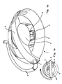
- the inner lamp body 6, outer reflector 9 and connecting web 3 provided light housing 1 via an axle connection 2 in the region of the connecting web 3 hinged to a bracket 4, which on a stationary bracket, especially customary ceiling mount is fixed for surgical lights.
- the mounting bracket 4 allows a gimbal adjustment of the luminaire housing, for optimal Positioning for illumination in the surgical field on the patient to achieve.
- the connecting web 3 of the inner lamp body 6 is connected, which here symbolically illustrated discharge lamp 7, that of an axially symmetrical lens arrangement 8 is surrounded for focusing the light emerging from the discharge lamp; the light is in the region of the plane of the inner lamp body 6 ring or polygonal surrounding reflector, which is also referred to as outer ring reflector 9, directed to the outside.
- Figure 1b shows a top plan view of the inner lamp body 6 with him in the radial Direction surrounding outer ring reflector 9, both parts through the connecting web 3 held together.
- Between the inner lamp body 6 and the ring reflector 9 is except for the area covered by the connecting land 3, respectively a sector of a concentric opening 11, 12 recognizable, whereby an unobstructed passage The air flow is possible, so that a laminar flow of the air-conditioning ceiling is not disturbed becomes. Thus it is prevented that any impurities from the environment in the reach the actual area of the surgical field. This is further supported by the fact that the housing of the outer reflector 9 remains cold during operation of the lamp.
- the ring reflector 9 has, according to FIG. 2, its direction towards the inner lamp body 6 Side on a closed transparent surface on the back of a reflective Layer 17 is applied.
- the reflective surface is smooth on its surface, while outside, i. on the inner lamp body side facing a scattering structure 18 has.
- the scattering structure has the particular advantage of rendering the surface insensitive against scratching and ensures an even distribution of light in the field.
- the reflective layer 17 is protected by a ring housing 23, which consists on its outwardly directed side 24 made of plastic. It proves to be advantageous that both the inner lamp body 6 of the ring housing, as well as the ring reflector 9 have a smooth or slightly textured outer surface, so that they can be cleaned together with connecting web 3 in a simple manner, as it is for medical applications is required.
- the longitudinal axis of the lamp body is designated by reference numeral 21.
- the inner lamp body has at the bottom of a handle 15 for optimum positioning of the surgical light with respect to the surgical field.
- an additional protective screen for covering the ring reflector which at the same time would mean a loss of intensity due to damping, dispensed with become. This in turn results in a lower weight of the lamp body.
- a for the commissioning of the discharge lamp required ignitor 16 in the range between Handle 15 for adjusting the lamp and a first socket 19 for the discharge lamp 7, or alternatively above a second socket 22 of the discharge lamp 7 is in position 20; the discharge lamp 7 is additionally arranged by a along the lamp axis 21 second version 22 held, the contacting of the first and second version a sufficiently high ignition voltage allows, without any voltage flashovers may occur.
- the emerging from the discharge lamp 7 radiation is through the bundling directed in the radial direction to the outer ring reflector (not shown here), so that high-intensity radiation hits the reflective area of the ring reflector, which then converges along the direction of the lamp axis 21 and thus the Illuminated illumination field on the patient.
- the intended as a reserve lamp 10 halogen bulb is in the immediate vicinity of the side Discharge lamp 7 is arranged so that the beam path of its exiting light substantially which corresponds to the discharge lamp 7.
Landscapes
- Engineering & Computer Science (AREA)
- General Engineering & Computer Science (AREA)
- Non-Portable Lighting Devices Or Systems Thereof (AREA)
- Securing Globes, Refractors, Reflectors Or The Like (AREA)
- Arrangement Of Elements, Cooling, Sealing, Or The Like Of Lighting Devices (AREA)
Description
Der innere Leuchtenkörper weist im unteren Bereich einen Handgriff 15 zur optimalen Positionierung der Operationsleuchte im Hinblick auf das Operationsfeld auf.
Claims (9)
- Operationsleuchte mit einem inneren Leuchtenkörper, der wenigstens eine Lampe und einen inneren Reflektor in einem Gehäuse aufweist, wobei der Leuchtenkörper wenigstens teilweise von einem äußeren ringartigen Gehäuse mit einem ring- oder polygonartig ausgebildeten Reflektor zur konvergierenden Umlenkung von aus dem Leuchtenkörper austretendem Licht in ein Beleuchtungsfeld umgeben ist, dadurch gekennzeichnet, dass der äußere Reflektor (9) auf seiner zum inneren Leuchtenkörper (6) gerichteten Seite eine transparente Fläche aufweist, deren Rückseite an eine reflektierende Schicht angrenzt und dass der innere Leuchtenkörper (6) und der äußere Reflektor (9) durch einen Verbindungssteg (3) zusammengehalten werden, welcher mit einem Bügel (4) zur Befestigung an einer stationären Halterung gelenkig verbunden ist.
- Operationsleuchte nach Anspruch 1, dadurch gekennzeichnet, dass die reflektierende Schicht auf die Rückseite der transparenten Fläche aufgebracht ist.
- Operationsleuchte nach Anspruch 1 oder 2, dadurch gekennzeichnet, dass als Lampe für Normalbetrieb eine Entladungslampe eingesetzt ist.
- Operationsleuchte nach einem der Ansprüche 1 bis 3, dadurch gekennzeichnet, dass der innere Leuchtenkörper (6) eine zusätzliche Lichtquelle als Reserve-Lampe (10) aufweist, deren Strahlung wenigstens zum Teil über die vorhandene optische Anordnung zur Bündelung des aus der Entladungslampe austretenden Lichts geführt wird.
- Operationsleuchte nach einem der Ansprüche 1 bis 4, dadurch gekennzeichnet, dass der Ring-Reflektor (9) auf seiner zum inneren Leuchtenkörper (6) gerichteten Seite eine Streustruktur (18) aufweist.
- Operationsleuchte nach Anspruch 5, dadurch gekennzeichnet, dass die Streustruktur auf der transparenten Fläche des Ring-Reflektors (9) angeordnet ist.
- Operationsleuchte nach einem der Ansprüche 1 bis 6, dadurch gekennzeichnet, dass ein Vorschaltgerät zum Betrieb der Lampe im Verbindungssteg (3) außerhalb des inneren Leuchtenkörpers (6) angeordnet ist.
- Operationsleuchte nach einem der Ansprüche 3 bis 7, dadurch gekennzeichnet, dass ein Zündgerät zum Starten der Entladungslampe direkt oberhalb oder unterhalb der Lampe angeordnet ist.
- Operationsleuchte nach einem der Ansprüche 1 bis 8, dadurch gekennzeichnet, dass Ring-Reflektor (9) wenigstens zwei Segmente aufweist.
Applications Claiming Priority (2)
| Application Number | Priority Date | Filing Date | Title |
|---|---|---|---|
| DE20004384U DE20004384U1 (de) | 2000-03-13 | 2000-03-13 | Operationsleuchte mit einem Leuchtenkörper, der eine Entladungslampe aufweist |
| DE20004384U | 2000-03-13 |
Publications (3)
| Publication Number | Publication Date |
|---|---|
| EP1134481A2 EP1134481A2 (de) | 2001-09-19 |
| EP1134481A3 EP1134481A3 (de) | 2003-05-14 |
| EP1134481B1 true EP1134481B1 (de) | 2005-08-31 |
Family
ID=7938520
Family Applications (1)
| Application Number | Title | Priority Date | Filing Date |
|---|---|---|---|
| EP01101226A Expired - Lifetime EP1134481B1 (de) | 2000-03-13 | 2001-01-19 | Operationsleuchte mit einem Leuchtenkörper, der eine Entladungslampe aufweist |
Country Status (4)
| Country | Link |
|---|---|
| US (1) | US6511210B2 (de) |
| EP (1) | EP1134481B1 (de) |
| JP (1) | JP3597480B2 (de) |
| DE (2) | DE20004384U1 (de) |
Families Citing this family (5)
| Publication number | Priority date | Publication date | Assignee | Title |
|---|---|---|---|---|
| DE10156307B4 (de) | 2001-11-19 | 2006-01-05 | Maquet Gmbh & Co. Kg | Leuchtenkörper für eine medizinische Leuchte sowie dessen Verwendung |
| USD495081S1 (en) | 2002-10-23 | 2004-08-24 | Alm | Combined operating, examination and diagnosis lighting fixture |
| JP5072830B2 (ja) | 2005-04-12 | 2012-11-14 | プランメカ オイ | 手術用ライト |
| DE102005036275A1 (de) * | 2005-08-02 | 2007-02-08 | Berchtold Holding Gmbh | Operationsleuchte |
| US10512438B2 (en) | 2015-01-20 | 2019-12-24 | Koninklijke Philips N.V. | Medical imaging with integrated air guidance |
Family Cites Families (9)
| Publication number | Priority date | Publication date | Assignee | Title |
|---|---|---|---|---|
| US3786244A (en) * | 1972-10-02 | 1974-01-15 | Physical Syst Inc | Surgical lamp |
| DE3405739A1 (de) * | 1984-02-17 | 1985-08-22 | Hartmann & Unger GmbH, 4619 Bergkamen | Leuchte, vorzugsweise zur arbeitsplatzbeleuchtung |
| DE3432745C2 (de) * | 1984-09-06 | 1986-08-14 | W.C. Heraeus Gmbh, 6450 Hanau | Operationsleuchte zur gleichmäßigen Ausleuchtung eines Operationsfeldes ohne Schlagschatten |
| US4600979A (en) * | 1985-10-02 | 1986-07-15 | American Sterilizer Company | Passive cooling system for a luminaire |
| DE4140325C2 (de) * | 1991-12-06 | 2003-07-31 | Delma Elektro Med App | Operationsleuchte |
| DE19615388A1 (de) * | 1996-04-18 | 1997-10-23 | Zumtobel Licht | Leuchte mit einer insbesondere kleinvolumigen Lampe |
| US5791768A (en) * | 1997-04-17 | 1998-08-11 | Stingray Lighting, Inc. | Dual reflector lighting system |
| US5861706A (en) * | 1997-06-10 | 1999-01-19 | Osram Sylvania Inc. | Electrodeless high intensity discharge medical lamp |
| DE29906721U1 (de) * | 1999-04-15 | 1999-07-08 | Medline Enterprise Co., Ltd., Taipeh/T'ai-pei | Operationslampe |
-
2000
- 2000-03-13 DE DE20004384U patent/DE20004384U1/de not_active Expired - Lifetime
-
2001
- 2001-01-19 DE DE50107244T patent/DE50107244D1/de not_active Expired - Fee Related
- 2001-01-19 EP EP01101226A patent/EP1134481B1/de not_active Expired - Lifetime
- 2001-03-12 JP JP2001069320A patent/JP3597480B2/ja not_active Expired - Fee Related
- 2001-03-13 US US09/805,087 patent/US6511210B2/en not_active Expired - Fee Related
Also Published As
| Publication number | Publication date |
|---|---|
| EP1134481A2 (de) | 2001-09-19 |
| DE50107244D1 (de) | 2005-10-06 |
| JP2001283608A (ja) | 2001-10-12 |
| EP1134481A3 (de) | 2003-05-14 |
| DE20004384U1 (de) | 2000-10-26 |
| JP3597480B2 (ja) | 2004-12-08 |
| US20010030867A1 (en) | 2001-10-18 |
| US6511210B2 (en) | 2003-01-28 |
Similar Documents
| Publication | Publication Date | Title |
|---|---|---|
| DE2817903C2 (de) | ||
| DE19655357B4 (de) | Fahrzeug-Scheinwerfer | |
| DE112004001245B4 (de) | Leuchte für ein Fahrzeug | |
| DE69402379T2 (de) | Einrichtung und Verfahren zur Beleuchtung von Lichtleitern und von der Umgebung | |
| EP0446423A1 (de) | Leuchte | |
| EP0846915A1 (de) | Innenraumleuchte | |
| DE10219246A1 (de) | Beleuchtungseinrichtung für Kraftfahrzeuge | |
| EP2884155B1 (de) | Leuchte mit Lichtleiter | |
| DE102015106708A1 (de) | Vorrichtung zur Emission von Licht, insbesondere zur Erzeugung eines Bildes | |
| DE102010014839B4 (de) | Einbauleuchte | |
| DE19645023A1 (de) | Lampenvorrichtung eines Flüssigkristall-Projektionsgerätes | |
| DE1259747B (de) | Anordnung zum Verhindern von Phantomlicht in einer Signallichtanlage fuer Automobileod. dgl. | |
| EP0976971A2 (de) | Licht emittierende Einrichtung, insbesondere Leuchte oder Laterne | |
| EP1894516B1 (de) | Beleuchtungssystem zum Erzeugen von Licht und zum Einkoppeln des Lichts in ein proximales Ende eines Lichtleitkabels einer Beobachtungsvorrichtung für die Endoskopie oder Mikroskopie | |
| DE2032229A1 (de) | Beleuchtungskörper | |
| EP1134481A2 (de) | Operationsleuchte mit einem Leuchtenkörper, der eine Entladungslampe aufweist | |
| EP1039217A1 (de) | Leuchtkörperaufbau | |
| DE102019123515A1 (de) | Kraftfahrzeugscheinwerfer mit zwei Projektionslichtmodulen unterschiedlicher Brennweite und gleich breit ausgeleuchteten Lichtaustrittslinsen | |
| DE2348347A1 (de) | Verfahren zur beleuchtung von gegenstaenden sowie anordnung zur durchfuehrung des verfahrens | |
| DE69804683T2 (de) | Thermisch isolierendes verbindungselement für ein beleuchtungssystem mit lichtleiter | |
| EP1650491B1 (de) | Leuchte zur Ausleuchtung einer Gebäudefläche oder einer Gebäudeteilfläche | |
| EP0528127A2 (de) | Beleuchtungskörper, insbesondere Unterflurleuchte | |
| DE2930308A1 (de) | Beleuchtungsanordnung fuer ein operationsfeld | |
| EP0703405A1 (de) | Faseroptische Beleuchtungseinrichtung | |
| DE4233930A1 (de) | Leuchte, insbesondere wand- oder deckenstrahler |
Legal Events
| Date | Code | Title | Description |
|---|---|---|---|
| PUAI | Public reference made under article 153(3) epc to a published international application that has entered the european phase |
Free format text: ORIGINAL CODE: 0009012 |
|
| 17P | Request for examination filed |
Effective date: 20010126 |
|
| AK | Designated contracting states |
Kind code of ref document: A2 Designated state(s): AT BE CH CY DE DK ES FI FR GB GR IE IT LI LU MC NL PT SE TR |
|
| AX | Request for extension of the european patent |
Free format text: AL;LT;LV;MK;RO;SI |
|
| PUAL | Search report despatched |
Free format text: ORIGINAL CODE: 0009013 |
|
| AK | Designated contracting states |
Designated state(s): AT BE CH CY DE DK ES FI FR GB GR IE IT LI LU MC NL PT SE TR |
|
| AX | Request for extension of the european patent |
Extension state: AL LT LV MK RO SI |
|
| AKX | Designation fees paid |
Designated state(s): DE FR GB IT |
|
| 17Q | First examination report despatched |
Effective date: 20040405 |
|
| GRAP | Despatch of communication of intention to grant a patent |
Free format text: ORIGINAL CODE: EPIDOSNIGR1 |
|
| GRAS | Grant fee paid |
Free format text: ORIGINAL CODE: EPIDOSNIGR3 |
|
| GRAA | (expected) grant |
Free format text: ORIGINAL CODE: 0009210 |
|
| AK | Designated contracting states |
Kind code of ref document: B1 Designated state(s): DE FR GB IT |
|
| RAP1 | Party data changed (applicant data changed or rights of an application transferred) |
Owner name: MAQUET GMBH & CO. KG |
|
| REG | Reference to a national code |
Ref country code: GB Ref legal event code: FG4D Free format text: NOT ENGLISH |
|
| REF | Corresponds to: |
Ref document number: 50107244 Country of ref document: DE Date of ref document: 20051006 Kind code of ref document: P |
|
| GBT | Gb: translation of ep patent filed (gb section 77(6)(a)/1977) |
Effective date: 20051125 |
|
| PGFP | Annual fee paid to national office [announced via postgrant information from national office to epo] |
Ref country code: IT Payment date: 20060131 Year of fee payment: 6 |
|
| ET | Fr: translation filed | ||
| PLBE | No opposition filed within time limit |
Free format text: ORIGINAL CODE: 0009261 |
|
| STAA | Information on the status of an ep patent application or granted ep patent |
Free format text: STATUS: NO OPPOSITION FILED WITHIN TIME LIMIT |
|
| 26N | No opposition filed |
Effective date: 20060601 |
|
| PGFP | Annual fee paid to national office [announced via postgrant information from national office to epo] |
Ref country code: DE Payment date: 20090219 Year of fee payment: 9 |
|
| PGFP | Annual fee paid to national office [announced via postgrant information from national office to epo] |
Ref country code: GB Payment date: 20090123 Year of fee payment: 9 |
|
| PG25 | Lapsed in a contracting state [announced via postgrant information from national office to epo] |
Ref country code: IT Free format text: LAPSE BECAUSE OF NON-PAYMENT OF DUE FEES Effective date: 20070119 |
|
| PGFP | Annual fee paid to national office [announced via postgrant information from national office to epo] |
Ref country code: FR Payment date: 20090120 Year of fee payment: 9 |
|
| GBPC | Gb: european patent ceased through non-payment of renewal fee |
Effective date: 20100119 |
|
| REG | Reference to a national code |
Ref country code: FR Ref legal event code: ST Effective date: 20100930 |
|
| PG25 | Lapsed in a contracting state [announced via postgrant information from national office to epo] |
Ref country code: FR Free format text: LAPSE BECAUSE OF NON-PAYMENT OF DUE FEES Effective date: 20100201 |
|
| PG25 | Lapsed in a contracting state [announced via postgrant information from national office to epo] |
Ref country code: DE Free format text: LAPSE BECAUSE OF NON-PAYMENT OF DUE FEES Effective date: 20100803 |
|
| PG25 | Lapsed in a contracting state [announced via postgrant information from national office to epo] |
Ref country code: GB Free format text: LAPSE BECAUSE OF NON-PAYMENT OF DUE FEES Effective date: 20100119 |