EP1133258B1 - Apparatus for tissue imaging - Google Patents
Apparatus for tissue imaging Download PDFInfo
- Publication number
- EP1133258B1 EP1133258B1 EP99958221A EP99958221A EP1133258B1 EP 1133258 B1 EP1133258 B1 EP 1133258B1 EP 99958221 A EP99958221 A EP 99958221A EP 99958221 A EP99958221 A EP 99958221A EP 1133258 B1 EP1133258 B1 EP 1133258B1
- Authority
- EP
- European Patent Office
- Prior art keywords
- stretching
- tissue
- traction
- imaged
- contact
- Prior art date
- Legal status (The legal status is an assumption and is not a legal conclusion. Google has not performed a legal analysis and makes no representation as to the accuracy of the status listed.)
- Expired - Lifetime
Links
- 238000003384 imaging method Methods 0.000 title claims abstract description 71
- 238000007906 compression Methods 0.000 claims abstract description 67
- 230000006835 compression Effects 0.000 claims abstract description 66
- 238000000034 method Methods 0.000 claims abstract description 43
- 239000000463 material Substances 0.000 claims abstract description 8
- 230000008569 process Effects 0.000 claims description 13
- 210000000481 breast Anatomy 0.000 claims description 11
- 238000013459 approach Methods 0.000 claims description 2
- 238000009607 mammography Methods 0.000 abstract description 15
- 238000005516 engineering process Methods 0.000 description 10
- 230000005855 radiation Effects 0.000 description 8
- 206010028980 Neoplasm Diseases 0.000 description 2
- 230000005856 abnormality Effects 0.000 description 2
- 230000009286 beneficial effect Effects 0.000 description 2
- 230000008901 benefit Effects 0.000 description 2
- 230000005540 biological transmission Effects 0.000 description 2
- 239000013013 elastic material Substances 0.000 description 2
- 238000012360 testing method Methods 0.000 description 2
- 238000002604 ultrasonography Methods 0.000 description 2
- 230000032683 aging Effects 0.000 description 1
- 230000004075 alteration Effects 0.000 description 1
- 229920002678 cellulose Polymers 0.000 description 1
- 239000001913 cellulose Substances 0.000 description 1
- 230000008859 change Effects 0.000 description 1
- 210000000038 chest Anatomy 0.000 description 1
- 238000013461 design Methods 0.000 description 1
- 238000001514 detection method Methods 0.000 description 1
- 239000000284 extract Substances 0.000 description 1
- 239000004744 fabric Substances 0.000 description 1
- 230000002349 favourable effect Effects 0.000 description 1
- 238000011065 in-situ storage Methods 0.000 description 1
- 238000009434 installation Methods 0.000 description 1
- 230000003902 lesion Effects 0.000 description 1
- 229910052751 metal Inorganic materials 0.000 description 1
- 239000002184 metal Substances 0.000 description 1
- 150000002739 metals Chemical class 0.000 description 1
- 230000003287 optical effect Effects 0.000 description 1
- 239000004033 plastic Substances 0.000 description 1
- 229920003023 plastic Polymers 0.000 description 1
- 239000002985 plastic film Substances 0.000 description 1
- 229920006255 plastic film Polymers 0.000 description 1
- 230000009467 reduction Effects 0.000 description 1
- 238000011012 sanitization Methods 0.000 description 1
- 238000012216 screening Methods 0.000 description 1
- 230000035882 stress Effects 0.000 description 1
- 210000000779 thoracic wall Anatomy 0.000 description 1
- 238000012546 transfer Methods 0.000 description 1
Images


Classifications
-
- A—HUMAN NECESSITIES
- A61—MEDICAL OR VETERINARY SCIENCE; HYGIENE
- A61B—DIAGNOSIS; SURGERY; IDENTIFICATION
- A61B6/00—Apparatus or devices for radiation diagnosis; Apparatus or devices for radiation diagnosis combined with radiation therapy equipment
- A61B6/04—Positioning of patients; Tiltable beds or the like
- A61B6/0407—Supports, e.g. tables or beds, for the body or parts of the body
- A61B6/0414—Supports, e.g. tables or beds, for the body or parts of the body with compression means
-
- A—HUMAN NECESSITIES
- A61—MEDICAL OR VETERINARY SCIENCE; HYGIENE
- A61B—DIAGNOSIS; SURGERY; IDENTIFICATION
- A61B6/00—Apparatus or devices for radiation diagnosis; Apparatus or devices for radiation diagnosis combined with radiation therapy equipment
- A61B6/50—Apparatus or devices for radiation diagnosis; Apparatus or devices for radiation diagnosis combined with radiation therapy equipment specially adapted for specific body parts; specially adapted for specific clinical applications
- A61B6/502—Apparatus or devices for radiation diagnosis; Apparatus or devices for radiation diagnosis combined with radiation therapy equipment specially adapted for specific body parts; specially adapted for specific clinical applications for diagnosis of breast, i.e. mammography
-
- A—HUMAN NECESSITIES
- A61—MEDICAL OR VETERINARY SCIENCE; HYGIENE
- A61B—DIAGNOSIS; SURGERY; IDENTIFICATION
- A61B6/00—Apparatus or devices for radiation diagnosis; Apparatus or devices for radiation diagnosis combined with radiation therapy equipment
- A61B6/44—Constructional features of apparatus for radiation diagnosis
- A61B6/4423—Constructional features of apparatus for radiation diagnosis related to hygiene or sterilisation
Definitions
- Imaging has become a proven method for the detection of e.g. cancers and other abnormalities before they advance to a phase that is difficult to treat or incurable.
- tissue to be imaged One of the methods utilized for the positioning of tissue, especially in mammography, is compression of the tissue to be imaged.
- the main reason for compressing tissue is to keep it in place during the imaging process.
- the tissue layer to be imaged gets thinner, the amount of radiation also gets smaller and the imaging time is shortened, which further reduces the inaccuracies caused by movement of the tissue under exposure.
- the contrast of the image improves as scattering is reduced, which simultaneously enables the use of lower imaging values (kV).
- resolution improves, the film darkens more homogeneously, and the result is a diagnostically more valuable image, since possible deviations of superimposed tissue layers are more effectively differentiated from each other.
- the object of the invention presented here is to raise the level of technology in the field of positioning methods related to tissue imaging.
- one target of the invention presented herein is to develop the technology based on tissue stretching means so as to speed up the practical process of imaging.
- Another target of the invention is to provide a solution whereby the tissue stretching means could be simply, quickly and easily fed and fastened to a tissue pulling device, thereby resulting in a reduction of the total imaging time and eliminating difficult installation procedures.
- Another target of the invention is to provide a solution to feeding the stretching means into the traction device in such a way that a sheet-like stretching means, or stretching means of some other, in its principal dimensions essentially a rectangular configuration, could be fed into the traction device as easily as a bank card or a note is fed into an automatic cash dispenser, or the like.
- Another target of the invention is also to provide a solution for fastening the tissue-stretching means to the tissue-stretching device so as to guarantee a rapid, secure and non-slip lockage of the stretching means to the traction device.
- the aim of the invention is to provide such a solution for fastening the stretching means to the traction device, as well as to provide such a traction device, that the stretching means can be both pulled into the device as well as driven out of it.
- Another target of the invention is also to provide an imaging system that utilizes tissue traction technology whereby the imaging methods and imaging sequences typically used in mammography can be applied simply, efficiently and, if so desired, to some degree automatically.
- the aim of the invention is also to enable the utilization of all those components generally used in mammography, such as the various compression paddles, image information receivers, grids, etc., in the same fashion as before.
- the invention is illustrated with reference to an x-ray application. To a professional in this field, it is self-evident which parts the structure of the ultrasound device adapted for the invention would deviate from the structure of the x-ray apparatus presented here.
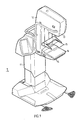
- a typical mammography x-ray apparatus 1 comprises a body part 11 and a C-arm 12, or a corresponding part, connected to the body part 11, when typically a radiation source 13 and a radiation receiver 14 (not actually shown in the figure) are situated at the opposite ends of the C-arm 12.
- C-arm 12 can be moved vertically and rotated in relation to the body part 11.
- compression paddles 15, 16 it is typical for compression paddles 15, 16 to be used in the apparatus, one of which is often structurally attached to the radiation receiver 14.
- the apparatus is typically equipped with means (not shown in the figure) for changing the height position of the compression paddles 15, 16 in relation to C-arm 12.
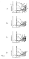
- Figure 2 depicts the general principle for traction of the tissue to be imaged in accordance with prior art in connection with a mammography apparatus utilizing compression technology.
- compression is a beneficial method from the view-point of applying the invention, the mere contact of the compression paddles with the stretching means and through it to the tissue to be imaged could in some applications of the invention be sufficient.
- stretching means 21 can comprise, for example, a continuous band of film that is positioned to move along the contact or compression surfaces 22, 23 of compression paddles 15, 16 and through the traction device not shown in the figure.
- the traction device can be situated, for example, within the C-arm 12, in which case it is equipped with means for pulling the stretching means 21 approximately from its center towards the C-arm 12.
- the tissue to be imaged 20 could be placed in the pouch-shaped space open at the sides created by the stretching means 21.
- the stretching device could comprise a ring-shaped stretching means 21 moving around either one or the other or around both individual compression paddles 15, 16, as well as being comprised of a transport device for either of such stretching means 21.
- the tissue imaging process is initiated by moving, for example, the upper compression paddle 15 towards the lower compression paddle 16 (2a), such that the tissue to be imaged 20 gets evenly spread out over the imaging space (2b).
- the traction of tissue 20 within the imaging space is initiated by starting up the traction device or a separate conveyor device, not shown in the figure, which moves 25 the stretching means 21 in relation to the contact or compression surfaces 22, 23, whereby the tissue to be imaged 20 starts stretching in the direction of traction 26 and tissue located outside the space of contact or compression surfaces 22, 23 starts moving towards the imaging space (2c).
- the image to be taken of tissue 20 will comprise such tissue that would normally remain outside the imaging space and where lesions 27 often occur (2d).
- the amount of the movement of tissue does not have to be at all large. For example, the transfer of a few millimeters can already be diagnostically significant.
- Figure 3 depicts one traction device 30 according to the invention that comprises a rotating axle, cylinder or drum 31, one or several means 32 for locking the stretching means 21, the operating part of which consists of, e.g., an eccentric wedge 33, a compressor spring 34 of the eccentric wedge 33, one or several guides 35 for the stretching means, and the release bar 36 of the eccentric wedge 33 or a corresponding component.
- the stretching device may comprise a receiver means for the stretching means, in figure 3 a wedge-shaped aperture 37 of the guide 35 of the stretching means 21.
- a motor 38 and power transmission means not shown in the figure, drive the stretching device 30.
- FIGs 4a-c describe the functioning of the stretching device 30 as shown in figure 3.
- Stretching means 21, which is made of elastic material and is advantageously substantially rectangular in shape, is fed into the wedge-shaped receiving aperture 37 that directs stretching means 21 into a position between the cylinder 31, which can be rotated, and the eccentric wedge 33 (4a).
- the compressor spring 34 of the eccentric wedge 33 assists the engagement of the stretching means 21 between the wedge 33 and the cylinder 31, but the actual locking is based on the structure of the eccentric wedge 33 itself and the fixation of it to the stretching device 30.
- the eccentric wedge 33 tends to continuously adhere itself more closely to the cylinder 31, when the stretching means 21 that is fed into the space between the cylinder 31 and the eccentric wedge 33 is exposed to a force from the direction that extracts it from device 30.
- the stretching means 21 is pulled by the rotating cylinder 31.
- the dimensions and gear ratios between the stretching device 30 and the power transmission means can be such, for example, that rotation of cylinder 31 for half a cycle is sufficient to pull stretching means 21 to the supposed maximum distance, for example 50 mm (4b).
- Stretching means 21 is disengaged by rotating cylinder 31 in the opposite direction, whereby the sheath-like guide 35 that covers cylinder 31 feeds stretching means 21 from device 30 and the lock of stretching means 21 is released when the eccentric wedge 33 comes into contact with the release bar 36 that turns the eccentric wedge 3 so that it disconnects with the surface of the cylinder 31 (4c).
- Stretching device 30 may also comprise means, not shown in the figures, for identification of the feeding of the stretching means 21.
- micro switch can be installed that would react when coming into contact with stretching mean 21.
- guide 35 can be equipped with components for the optical identification o the stretching means 21.
- Identification can also be specifically arranged so that the type o stretching means 21 fed into device 30 can be identified.
- the control system may include a signal route from identification means to traction or transport means, and the contro system may be pre-programmed with typical imaging process parameters for each stretching means.
- Stretching device 30 can contain e.g. automatic control systems for locking the stretching means 21 based on an identification signal, e.g.
- the whole imaging process can be automated according to the pre-programmed parameters of the apparatus, among other things when the compression ceases, the stretching means can be fed out of the device either to its initial position of imaging process, or entirely out of the device.
- the arrangement can also comprise identification means for the traction force and traction distance of stretching means 21.
- identification means for the traction force and traction distance of stretching means 21 it is possible to arrange several stretching devices 30 that can be controlled independently of each other, thus making it possible to drive them, if so desired, by stretching the tissue only on one side or by stretching it from different sides for distances of variable length and/or by stretching tissue from different sides at different speeds.
- Device 30 can also be programmed to encompass different traction sequences or traction-related security limit values such as, for example, the maximum traction force of the stretching means and/or limit values of the maximum stretching length, which can amount to e.g. 300 N for the traction force, 50 mm for the stretching length and 20 mm/s for the stretching speed, whereby typical values in use would be somewhat lower than these limit values.
- stretching device 30 do not have to comply in all their details with the above-mentioned advantageous embodiments.
- the locking of stretching means 21 to the stretching device can also be implemented in other ways, for example with a locking device attached to some sort of gliding cradle.
- one advantageous way of implementing the stretching movement would be to move the cradle along a suitable groove, or corresponding element for controlling movement, advantageously in a linear fashion.
- the traction means consists of two substantially parallel axles; both equipped essentially at their ends with intermeshing groove, gear or corresponding structures.
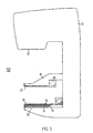
- FIG. 5 shows how a stretching device 30, in accordance with the invention, can be integrated for example, in a C-arm structure 12 typical to a mammography apparatus 1 in order to form a tissue positioning apparatus 50 according to the invention.
- the C-arm 12 includes the upper and lower compression paddles 15, 16, which are movable in relation to the C-arm, a cassette tunnel 51 coupled to the lower compression paddle 16, a movable grid 52, the so-called bucky, and the upper and lower stretching devices 30 in an essential vicinity of the compression paddles.
- a radiation receiver 14 of the desired type can be attached to the cassette tunnel 51, while the radiation source 13 is located on the opposite frame of the C-arm structure 12.
- the imaging process can be speeded up by simultaneously making the compression and stretching movements, as well as their counter movements.
- This type of simultaneous stretching and compression method can also be automated as a function of the increase of compression force and the decrease of compression thickness.
- the optimal compression force and pulling-speed/pulling-distance interdependence for various tissue types to be imaged can be determined by clinical tests.
- the tissue type can be identified, for example, by compression thickness and force, in which case e.g. a tissue with a great starting thickness, and with which a relatively small force is needed for compression, can be drawn in greater volume to the imaging area than a tissue with the opposite qualities. Automation can be done for example by first compressing for a short distance, e.g. until a specific compression force is reached, after which the tissue is both pulled and compressed and possibly separately pulled or compressed at the end.
- One of the advantages of the technique is that it makes it possible to use all of the imaging practices typically used in mammography without requiring any special arrangements due to the application of the invention. For example, it would be difficult to apply the magnification imaging typical in mammography to at least some of the prior art solutions since the stretching device arrangement would make changing the distance between the receiver and the imaging area difficult or even impossible.
- a stretching device in accordance with the invention can also be attached to an existing mammography apparatus with relatively small alterations.
- the stretching means it is not necessary that the actual form of the stretching means be that of a genuine rectangle. What is essential is that the stretching means can easily be fed into the stretching device from one end. However, from the point of view of locking the stretching means, it may be advantageous to design some kind of projection or projections at the feeding end of it, in order that the stretching device can easily grasp and lock the stretching means. Projections of this kind can e.g. be in the form of a rectangle or a triangle, either pointed or blunt, and they can form the whole group of projections covering the feeding end of the stretching means. The appropriate form of the feeding end can also be used as an implement according to which the stretching device specifically identifies the stretching means.
- Identifying the stretching means can, of course, be based on many other characteristics as well, such as the colour of the stretching means, a colour sticker or a bar code attached to the stretching means.
Landscapes
- Health & Medical Sciences (AREA)
- Life Sciences & Earth Sciences (AREA)
- Medical Informatics (AREA)
- Engineering & Computer Science (AREA)
- Optics & Photonics (AREA)
- Biomedical Technology (AREA)
- Biophysics (AREA)
- High Energy & Nuclear Physics (AREA)
- Veterinary Medicine (AREA)
- Nuclear Medicine, Radiotherapy & Molecular Imaging (AREA)
- Public Health (AREA)
- Pathology (AREA)
- Radiology & Medical Imaging (AREA)
- Physics & Mathematics (AREA)
- Heart & Thoracic Surgery (AREA)
- Molecular Biology (AREA)
- Surgery (AREA)
- Animal Behavior & Ethology (AREA)
- General Health & Medical Sciences (AREA)
- Dentistry (AREA)
- Oral & Maxillofacial Surgery (AREA)
- Apparatus For Radiation Diagnosis (AREA)
- Ultra Sonic Daignosis Equipment (AREA)
Applications Claiming Priority (3)
| Application Number | Priority Date | Filing Date | Title |
|---|---|---|---|
| FI982580A FI106293B (fi) | 1998-11-27 | 1998-11-27 | Menetelmä ja laitteet kudosten kuvantamisessa |
| FI982580 | 1998-11-27 | ||
| PCT/FI1999/000988 WO2000032109A1 (en) | 1998-11-27 | 1999-11-29 | Method and apparatus for tissue imaging |
Publications (2)
| Publication Number | Publication Date |
|---|---|
| EP1133258A1 EP1133258A1 (en) | 2001-09-19 |
| EP1133258B1 true EP1133258B1 (en) | 2004-09-22 |
Family
ID=8553001
Family Applications (1)
| Application Number | Title | Priority Date | Filing Date |
|---|---|---|---|
| EP99958221A Expired - Lifetime EP1133258B1 (en) | 1998-11-27 | 1999-11-29 | Apparatus for tissue imaging |
Country Status (7)
| Country | Link |
|---|---|
| US (1) | US6647089B1 (enExample) |
| EP (1) | EP1133258B1 (enExample) |
| JP (1) | JP4536930B2 (enExample) |
| AU (1) | AU1563800A (enExample) |
| DE (1) | DE69920504T2 (enExample) |
| FI (1) | FI106293B (enExample) |
| WO (1) | WO2000032109A1 (enExample) |
Families Citing this family (15)
| Publication number | Priority date | Publication date | Assignee | Title |
|---|---|---|---|---|
| FR2819329B1 (fr) * | 2001-01-11 | 2003-06-06 | Ge Med Sys Global Tech Co Llc | Procede et dispositif de detection automatique d'une pelote de compression graduee d'un appareillage de mammographie |
| FR2829918A1 (fr) | 2001-09-25 | 2003-03-28 | Ge Med Sys Global Tech Co Llc | Appareil de mammographie |
| FR2833100B1 (fr) | 2001-11-30 | 2004-03-12 | Ge Med Sys Global Tech Co Llc | Procede de reconstitution d'une image d'un organe |
| US8116845B2 (en) * | 2005-08-04 | 2012-02-14 | Dune Medical Devices Ltd. | Tissue-characterization probe with effective sensor-to-tissue contact |
| US8721565B2 (en) * | 2005-08-04 | 2014-05-13 | Dune Medical Devices Ltd. | Device for forming an effective sensor-to-tissue contact |
| US6974255B1 (en) * | 2002-08-28 | 2005-12-13 | American Mammographics, Inc. | Mammographic paddle |
| JP4837507B2 (ja) * | 2005-10-06 | 2011-12-14 | 富士フイルム株式会社 | 乳房画像撮影装置 |
| JP4769097B2 (ja) * | 2006-03-01 | 2011-09-07 | 富士フイルム株式会社 | マンモグラフィ装置及び該マンモグラフィ装置に用いられる乳房圧迫板 |
| JP5311846B2 (ja) * | 2008-02-29 | 2013-10-09 | 富士フイルム株式会社 | 画像処理方法および装置並びに放射線画像撮影処理方法および装置 |
| DE102008020670B4 (de) * | 2008-04-24 | 2016-05-04 | Siemens Aktiengesellschaft | Verfahren zur Erzeugung eines Bildes mit einem Mammographiegerät |
| US8401145B1 (en) * | 2008-10-23 | 2013-03-19 | Beekley Corporation | Imaging sheet and related method |
| FI123261B (fi) * | 2008-11-28 | 2013-01-15 | Planmed Oy | 3D mammografia |
| JP6945491B2 (ja) * | 2018-04-27 | 2021-10-06 | 富士フイルム株式会社 | マンモグラフィ装置 |
| EP4129183B1 (en) * | 2020-03-31 | 2025-09-17 | FUJIFILM Corporation | Information processing device, radiographic imaging device, information processing method, and information processing program |
| CN119745419B (zh) * | 2025-03-05 | 2025-07-15 | 上海交通大学医学院附属瑞金医院 | 一种乳腺外科肿瘤早期筛查诊断装置及方法 |
Family Cites Families (6)
| Publication number | Priority date | Publication date | Assignee | Title |
|---|---|---|---|---|
| DE2610830C3 (de) * | 1976-03-15 | 1978-09-07 | Siemens Ag, 1000 Berlin Und 8000 Muenchen | Spannvorrichtung zur Befestigung eines Patienten auf der Patientenlagerungsplatte eines Untersuchungsgerätes |
| DE2714695C3 (de) * | 1977-04-01 | 1979-09-20 | Siemens Ag, 1000 Berlin Und 8000 Muenchen | Fixiervorrichtung für einen Patienten |
| FR2447708A1 (fr) * | 1979-02-01 | 1980-08-29 | Deutsch Michel | Ceinture de securite pour table basculante, notamment de radiologie |
| SE463344B (sv) * | 1989-03-31 | 1990-11-12 | Ao Medical Products Ab | Krompressionsanordning foer roentgen och liknande undersoekning |
| US5553111A (en) * | 1994-10-26 | 1996-09-03 | The General Hospital Corporation | Apparatus and method for improved tissue imaging |
| US5851180A (en) * | 1996-07-12 | 1998-12-22 | United States Surgical Corporation | Traction-inducing compression assembly for enhanced tissue imaging |
-
1998
- 1998-11-27 FI FI982580A patent/FI106293B/fi active
-
1999
- 1999-11-29 US US09/856,800 patent/US6647089B1/en not_active Expired - Lifetime
- 1999-11-29 AU AU15638/00A patent/AU1563800A/en not_active Abandoned
- 1999-11-29 EP EP99958221A patent/EP1133258B1/en not_active Expired - Lifetime
- 1999-11-29 DE DE69920504T patent/DE69920504T2/de not_active Expired - Lifetime
- 1999-11-29 JP JP2000584811A patent/JP4536930B2/ja not_active Expired - Fee Related
- 1999-11-29 WO PCT/FI1999/000988 patent/WO2000032109A1/en not_active Ceased
Also Published As
| Publication number | Publication date |
|---|---|
| DE69920504T2 (de) | 2005-10-13 |
| FI982580L (fi) | 2000-05-28 |
| JP2002531156A (ja) | 2002-09-24 |
| FI982580A0 (fi) | 1998-11-27 |
| JP4536930B2 (ja) | 2010-09-01 |
| WO2000032109A1 (en) | 2000-06-08 |
| AU1563800A (en) | 2000-06-19 |
| DE69920504D1 (de) | 2004-10-28 |
| EP1133258A1 (en) | 2001-09-19 |
| US6647089B1 (en) | 2003-11-11 |
| FI106293B (fi) | 2001-01-15 |
Similar Documents
| Publication | Publication Date | Title |
|---|---|---|
| EP1133258B1 (en) | Apparatus for tissue imaging | |
| US4962515A (en) | Ridged compression assembly for mammography apparatus | |
| US6845146B2 (en) | Mammography apparatus and method | |
| JP4628793B2 (ja) | 組織露光制御、トモシンセシス及び動的視野処理を具備するフルフィールドマンモグラフィー | |
| US7746975B2 (en) | Breast's radiation image taking apparatus and a method of taking a breast's radiation image | |
| EP1908405A2 (en) | Dual-radiation type mammography apparatus and breast imaging method using the mammography | |
| DE19746096A1 (de) | Röntgeneinrichtung | |
| EP2168485A1 (de) | Brustfixierung für ein Untersuchungsgerät zur Untersuchung der weiblichen Brust | |
| EP3238628A1 (en) | Lifting apparatus for pressure paddle and x-ray image photographing device including same | |
| DE60320625T2 (de) | Röntgenvorrichtung und Verfahren | |
| FI120077B (fi) | Järjestely ja menetelmä digitaalisessa mammografiakuvauksessa | |
| EP1390956B1 (en) | Method and apparatus for limiting a ray beam | |
| DE69715897T2 (de) | Röntgengerät mit einer Bildaufnahmekassette | |
| EP3223699B1 (de) | Patientenliege für eine kernresonanztomographie-untersuchung | |
| US4539696A (en) | Target device for an X-ray examination installation | |
| EP0178538B1 (de) | Vorrichtung zum wahlweisen Aufnehmen und Durchleuchten eines Patienten | |
| DE60034700T2 (de) | Verfahren und vorrichtung zum empfang von mammografiebilddaten | |
| WO1996013211A1 (en) | Apparatus and method for improved tissue imaging | |
| CN105902277A (zh) | 胸部检查设备和用于胸部检查设备的压板 | |
| JP2012231889A (ja) | 放射線撮像装置 | |
| CN105120757A (zh) | 用于nmr乳房照影术的患者检查台 | |
| EP3220197B1 (de) | Speicherfolienzuführung | |
| JPS5839692Y2 (ja) | X線撮影装置 | |
| DE112022002760T5 (de) | Elektrisches oder manuelles nahtgerät mit getriebe | |
| EP2480134A1 (de) | Vorrichtung zur mammabiopsie |
Legal Events
| Date | Code | Title | Description |
|---|---|---|---|
| PUAI | Public reference made under article 153(3) epc to a published international application that has entered the european phase |
Free format text: ORIGINAL CODE: 0009012 |
|
| 17P | Request for examination filed |
Effective date: 20000704 |
|
| AK | Designated contracting states |
Kind code of ref document: A1 Designated state(s): AT BE CH CY DE DK ES FI FR GB GR IE IT LI LU MC NL PT SE |
|
| AX | Request for extension of the european patent |
Free format text: AL;LT;LV;MK;RO;SI |
|
| 17Q | First examination report despatched |
Effective date: 20011004 |
|
| GRAP | Despatch of communication of intention to grant a patent |
Free format text: ORIGINAL CODE: EPIDOSNIGR1 |
|
| RTI1 | Title (correction) |
Free format text: APPARATUS FOR TISSUE IMAGING |
|
| GRAS | Grant fee paid |
Free format text: ORIGINAL CODE: EPIDOSNIGR3 |
|
| GRAA | (expected) grant |
Free format text: ORIGINAL CODE: 0009210 |
|
| AK | Designated contracting states |
Kind code of ref document: B1 Designated state(s): DE FR GB IT SE |
|
| REG | Reference to a national code |
Ref country code: GB Ref legal event code: FG4D |
|
| REG | Reference to a national code |
Ref country code: IE Ref legal event code: FG4D |
|
| REF | Corresponds to: |
Ref document number: 69920504 Country of ref document: DE Date of ref document: 20041028 Kind code of ref document: P |
|
| PG25 | Lapsed in a contracting state [announced via postgrant information from national office to epo] |
Ref country code: SE Free format text: LAPSE BECAUSE OF FAILURE TO SUBMIT A TRANSLATION OF THE DESCRIPTION OR TO PAY THE FEE WITHIN THE PRESCRIBED TIME-LIMIT Effective date: 20041222 |
|
| LTIE | Lt: invalidation of european patent or patent extension |
Effective date: 20040922 |
|
| ET | Fr: translation filed | ||
| PLBE | No opposition filed within time limit |
Free format text: ORIGINAL CODE: 0009261 |
|
| STAA | Information on the status of an ep patent application or granted ep patent |
Free format text: STATUS: NO OPPOSITION FILED WITHIN TIME LIMIT |
|
| 26N | No opposition filed |
Effective date: 20050623 |
|
| PGFP | Annual fee paid to national office [announced via postgrant information from national office to epo] |
Ref country code: GB Payment date: 20101026 Year of fee payment: 12 |
|
| GBPC | Gb: european patent ceased through non-payment of renewal fee |
Effective date: 20111129 |
|
| PG25 | Lapsed in a contracting state [announced via postgrant information from national office to epo] |
Ref country code: GB Free format text: LAPSE BECAUSE OF NON-PAYMENT OF DUE FEES Effective date: 20111129 |
|
| REG | Reference to a national code |
Ref country code: FR Ref legal event code: PLFP Year of fee payment: 17 |
|
| REG | Reference to a national code |
Ref country code: FR Ref legal event code: PLFP Year of fee payment: 18 |
|
| PGFP | Annual fee paid to national office [announced via postgrant information from national office to epo] |
Ref country code: FR Payment date: 20161024 Year of fee payment: 18 Ref country code: DE Payment date: 20161020 Year of fee payment: 18 |
|
| PGFP | Annual fee paid to national office [announced via postgrant information from national office to epo] |
Ref country code: IT Payment date: 20161025 Year of fee payment: 18 |
|
| REG | Reference to a national code |
Ref country code: DE Ref legal event code: R119 Ref document number: 69920504 Country of ref document: DE |
|
| REG | Reference to a national code |
Ref country code: FR Ref legal event code: ST Effective date: 20180731 |
|
| PG25 | Lapsed in a contracting state [announced via postgrant information from national office to epo] |
Ref country code: FR Free format text: LAPSE BECAUSE OF NON-PAYMENT OF DUE FEES Effective date: 20171130 Ref country code: IT Free format text: LAPSE BECAUSE OF NON-PAYMENT OF DUE FEES Effective date: 20171129 Ref country code: DE Free format text: LAPSE BECAUSE OF NON-PAYMENT OF DUE FEES Effective date: 20180602 |