EP1132509B1 - Verfahren und Vorrichtung zum Steuern und Regeln der Plüschhenkelbildung in Frottierwebmaschinen - Google Patents
Verfahren und Vorrichtung zum Steuern und Regeln der Plüschhenkelbildung in Frottierwebmaschinen Download PDFInfo
- Publication number
- EP1132509B1 EP1132509B1 EP01104353A EP01104353A EP1132509B1 EP 1132509 B1 EP1132509 B1 EP 1132509B1 EP 01104353 A EP01104353 A EP 01104353A EP 01104353 A EP01104353 A EP 01104353A EP 1132509 B1 EP1132509 B1 EP 1132509B1
- Authority
- EP
- European Patent Office
- Prior art keywords
- terry
- lever
- hinge
- mechanical members
- roller
- Prior art date
- Legal status (The legal status is an assumption and is not a legal conclusion. Google has not performed a legal analysis and makes no representation as to the accuracy of the status listed.)
- Expired - Lifetime
Links
Images


Classifications
-
- D—TEXTILES; PAPER
- D03—WEAVING
- D03D—WOVEN FABRICS; METHODS OF WEAVING; LOOMS
- D03D39/00—Pile-fabric looms
- D03D39/22—Terry looms
- D03D39/223—Cloth control
Definitions
- the present invention concerns a device and a method to control and adjust the members which allow to form the loops in terry looms.
- it concerns a device of the aforementioned type, which allows to easily carry out wide adjustments of the motion laws for the rotary oscillating movements of the take-up roller and for the coordinate alternate translatory movements of the warp yarn guiding roller, which cause the forming of terry loops.
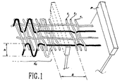
- these adjustments which will be indicated hereinafter “of motion law” and respectively “of amplitude” - are carried out by a control and adjustment device which is apt to produce a relative movement between the warp yarns and the weft yarns, such as to insert, at regular intervals, a weft yarn in an offset position (namely - as shown in fig. 1 - at a preset distance S from the fabric Te ) which, in the successive beating up, will allow to form the loops of the terry cloth.
- a control and adjustment device which is apt to produce a relative movement between the warp yarns and the weft yarns, such as to insert, at regular intervals, a weft yarn in an offset position (namely - as shown in fig. 1 - at a preset distance S from the fabric Te ) which, in the successive beating up, will allow to form the loops of the terry cloth.
- the fabric Te formed on the "weaving side” is shifted at a preset distance S, and kept there during insertion of the first two wefts t 1 and t 2 : before the beat-up of the third weft t 3 , the fabric Te is moved back to the initial position, thereby forming the loop with the regular beat-up of the weft t 3 .
- the first solution acts appropriately on the motion of the sley
- the second solution acts on the motion of the cloth holder, namely on the controlled and coordinate movement of the take-up roller and of the warp yarn guiding roller.
- Both movements are obtained by means of an electromechanical device, which receives the motion from the main shaft of the loom and transmits it to the members concerned through leverages, whose reciprocal engagement is preset by means of low-power actuators.
- EP-A-534.403 in the name of Somet Società Meccanica Tessile S.p.A., the contents of which may be used as reference for a better understanding of the present description.
- Said device comprises first mechanical members, in the form of cam means, to determine the law of the successive cyclic movements of the cloth holder, and second mechanical members, in the form of levers of different length, apt to determine the amplitude of the movement and thus the height of the terry loop.
- Such a device though apt to satisfactorily overcome many of the drawbacks of prior art, allows an automatic adjustment of the amplitude (that is, by using electromagnetically controlled mechanisms) only between three distinct values, one of them being a naught value. It is possible to preset intermediate values of amplitude, or differing from the three predermined values, only by performing manual operations on the kinematic mechanism, in order to change the position of a lever end inside an eyelet.
- EP 518.809 discloses a terry loop forming device according to the preamble of claim 1, where an articulated quadrilateral mechanism is provided and an actuating device is apt to change the length of a lever of said mechanism so as to adjust the amplitude of the motion.
- DE4432452 discloses a terry-loop-forming device where a single drive is used to determine the motion law and the amplitude of the loop-forming movement.
- the scope of the present invention is thus to solve also these further inconveniences of prior art, by supplying an adjustment device to control the cyclic movement of a cloth holder in a terry loom, which allows:
- the device to form terry loops is of the type comprising a drive shaft for transmission of a main rotary movement, and an outlet lever caused to rotate with an oscillating movement, between these two elements there being provided first mechanical members to determine the motion law and second mechanical members to adjust the amplitude of said oscillating movement in which actuating means are apt to change the geometrical position of a hinge of a kinematic chain of said second members, so that a specific transmission ratio and thus a given loop height may correspond to each of the geometrical positions taken up by said hinge.
- Fig. 1 is a diagrammatic perspective view of the weaving zone, illustrating the main parameters to form the loop in a terry cloth;
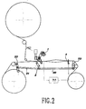
- Fig. 2 is a diagrammatic side elevation view of the main structure of the loom, into which is inserted the device according to the invention
- Figs. 3A and 3B are diagrammatic side elevation views of the device according to the invention, in a first working position for two different rotation angles of the drive shaft of the device;
- Figs. 4A and 4B are diagrammatic side elevation views of the device according to the invention, in a second working position for two different rotation angles of the drive shaft of the device.
- a main motor M1 of the weaving loom is mechanically connected in synchronism both with the sley 3 and with a drive shaft 1 of the device for terry loop formation.
- cams 4a and 4b (figs. 3A-4B) having a profile apt to determine the motion law for terry loop formation.
- said motion law for instance, modify the number of weft yarns being inserted before completion of the loop - said cams 4a and 4b can be easily replaced.
- the cams 4a and 4b transmit the motion to a rocking lever 5, which bears onto said cams by means of rollers 5a and 5b respectively, and which is pivoted in 5c. Having bound the lever 5 in the two rotation senses, there is no need to adopt any precautions (such as return springs) in order to keep the contact between the rollers 5a, 5b, and the cam surfaces 4a, 4b.
- the end of the rocking lever 5 has an eyelet 5d, of suitable length, into which is apt to freely slide a pin 6 fixed to a hinge forming part of an inlet side of an articulated quadrilateral kinematic mechanism.
- Said kinematic mechanism consists of an inlet rod 7, a connection rod 8 and an outlet lever 2.
- the connection rod 8 is pivoted, on one side, by means of the intermediate hinge-pin 6 to the inlet rod 7 and, on the other side, by means of another intermediate hinge 9 to the outlet lever 2.
- the outlet lever 2 oscillating about a first base hinge positioned in the fixed point J 1 , is the outlet lever of the terry loop formation device, since its end 2a is connected to rods 20 and 21 moving, respectively, the front cloth holder 22 and the warp yarn guiding roller 23.
- the inlet rod 7 is hinged at its other end onto a second base hinge 10 fixed to a shifting member.
- said member is in the form of an adjusting lever 11, hinged in a fixed axis J 2 and comprising a sector gear 12 extending over a circumferential path of a certain diameter and length.
- the sector gear 12 engages with a pinion 13 in the form of a worm screw, controlled by means of an auxiliary driving motor M2.
- the coupling between the worm screw 13 and the sector gear 12 forms an irreversible transmission: this represents an advantage, it being sufficient for the motor M2 to transmit a control only during adjustment, while it is no longer necessary for said motor to transmit any torque in steady running conditions, since the position of the shifting member 11 remains unvaried due to irreversibility of the coupling. It is thus evident that the auxiliary motor M2 can also have a low power and limited performances.
- the auxiliary motor M2 allows to change the angular position of the shifting member or adjusting lever 11 and thus the position of the second base hinge 10 which forms part of the articulated quadrilateral of apexes 10-6-9-J 1 . Consequently, also the transmission ratio between the inlet rod 7 and the outlet lever 2 is substantially modified: this allows to vary the amplitude of the oscillating movement transmitted, through the articulated quadrilateral mechanism, from the rocking lever 5 to the outlet lever 2.
- the motor M2 is preferably provided with an encoder allowing a microprocessor to detect the exact position of the adjusting lever 11, so as to preset the proper weaving program and that of terry loop formation.
- the inlet rod 7 and the connection rod 8 have the same length.
- the adjusting lever 11 (figs. 4A and 4B) in which the second movable base hinge 10 perfectly overlaps the intermediate hinge 9: in this condition, the motion of the rocking lever 5 is transmitted to the two rods 7 and 8, which oscillate together without any motion being transmitted to the outlet lever 2 which keeps motionless.
- no oscillating motion is transmitted by the device according to the invention to the cloth holder of the loom, thereby obtaining working conditions in which no terry loop is formed.
- the device according to the present invention it is thus possibile to continuously vary the amplitude of the oscillating movement allowing to form the terry loops, from a naught value corresponding to the normal working conditions of the loom, up to a maximum value determined by the dimensions of the elements of the aforedescribed kinematic chain.
- the device according to the present invention is extremely simple and consists of a comparatively small number of elements; it is easy to operate and requires a positive action of the auxiliary motor M2 only during adjustment, the shifting member 11 remaining motionless in a steady working condition; it allows, in a fully automatic way, to continuously vary the amplitude of the oscillating movement, starting from a naught value, without having to make use of ratchet gears or other mechanisms having to be disconnected.
- the shifting member instead of being in the form of an adjusting lever 11, could be in the form of a toothed sliding cursor apt to shift the hinge 10 along a rectilinear path, instead of a circumferential path.
Claims (9)
- Vorrichtung zum Steuern und Einstellen der Bewegungen der Aufnahmewalze und der den Kettfaden führenden Walze, die bei Frottierwebmaschinen das Bilden der Frottierschlaufen verursachen - von der Art mit einer Antriebswelle (1), die mit einem Hauptantrieb der Webmaschine verbunden ist, und mit einem Ausgangshebel (2) der dazu in der Lage ist, eine zyklische Bewegung auf die Aufnahmewalze und/oder die Führungswalze aufzubringen zwischen der Welle (1) und dem Hebel (2), der mit ersten mechanischen Elementen (4a, 4b, 5) zum Bestimmen des Bewegungsgesetzes und einer kinematischen Kette mit wenigstens einem vierseitigen Mechanismus (7, 8, 2) versehen ist, dadurch gekennzeichnet, dass sie weiter Betätigungsmittel (11, 13 M2) aufweist. die zur Änderung der geometrischen Position eines beweglichen Basisgelenks (10) des vierseitigen Mechanismus zum Einstellen des Übertragungsverhältnisses zwischen der Welle (1) und dem Hebel (2) eingerichtet sind.
- Vorrichtung nach Anspruch 1, wobei der vierseitige Mechanismus eine Eingangsstange (7), die durch die ersten mechanischen Elemente (4a, 4b, 5) gesteuert wird, eine Verbindungsstange (8) und eine Ausgangsstange, die den Ausgangshebel (2) bildet oder mit diesem einstückig ist, aufweist, wobei das bewegliche Basisgelenk (10) mit dem Basisgelenk entweder der Eingangsstange oder der Ausgangsstange übereinstimmt.
- Vorrichtung nach Anspruch 2, wobei das bewegliche Gelenk das Basisgelenk (10) der Eingangsstange (7) ist.
- Vorrichtung nach Anspruch 1, 2 oder 3 wobei das Betätigungsmittel einen Elektromotor (M2) aufweist, der zum Steuern eines Schiebelements zum Verschieben des beweglichen Gelenks (10) eingerichtet ist.
- Vorrichtung nach Anspruch 4, wobei das Schiebelement in der Form eines schwingenden Einstellhebels (11) ist, mit einem Sektorzahnrad, das mit einem entsprechenden Ritzel (13) des Elektromotors (M2) in Eingriff ist.
- Vorrichtung nach einem der Ansprüche 3 - 5, wobei die Eingangsstange (7) und die Verbindungsstange (8) gleich lang sind, so dass eine Position des beweglichen Gelenks (10) bestimmt werden kann, bei der der Ausgangshebel (2) während der Bewegung der ersten mechanischen Elemente bewegungslos verharrt.
- Vorrichtung nach einem der vorangehenden Ansprüche, wobei die ersten mechanischen Elemente einen Schwinghebel (5) aufweisen, der durch Nockenmittel (4a, 4b) gesteuert wird und ein Langloch (5d) aufweist, in der ein Stift (6), der an der Eingangsstange 7 des gelenkigen vierseitigen Mechanismus fixiert ist, frei gleiten kann.
- Verfahren zum Steuern und Einstellen der Bewegungen der Aufnahmewalze und der Kettfadenführungswalze bei Frottierwebmaschinen, die das Bilden der Frottierschlaufen verursacht - mit einer Frottierschlaufenbildungsvorrichtung einschließlich ersten mechanischen Elementen (4a, 4b, 5) zum Bestimmen des Bewegungsgesetzes und einem vierseitigen Mechanismus (7, 8, 2), dadurch gekennzeichnet, dass die Amplituden der Bewegungen, die das Bilden der Frottierschlaufen verursacht, durch Verschieben der Position des beweglichen Basiselements (10) des vierseitigen Mechanismus (7, 8, 2) variiert wird.
- Verfahren nach Anspruch 8, wobei der Null-Wert der Schwingungsamplitude, also der Arbeitsbedingung, in dem keine Frottierschlaufe gebildet wird, durch Bewirken, dass die Position des beweglichen Basisgelenks (10) mit der Position des nicht benachbarten Zwischengelenks (9) des vierseitigen Mechanismus (7, 8, 2) übereinstimmt, erreicht wird.
Applications Claiming Priority (2)
| Application Number | Priority Date | Filing Date | Title |
|---|---|---|---|
| ITMI000436 | 2000-03-07 | ||
| IT2000MI000436A IT1317119B1 (it) | 2000-03-07 | 2000-03-07 | Dispositivo di comando e regolazione per la formazione dei ricci intelai di tessitura di tipo a spugna |
Publications (2)
| Publication Number | Publication Date |
|---|---|
| EP1132509A1 EP1132509A1 (de) | 2001-09-12 |
| EP1132509B1 true EP1132509B1 (de) | 2005-04-06 |
Family
ID=11444333
Family Applications (1)
| Application Number | Title | Priority Date | Filing Date |
|---|---|---|---|
| EP01104353A Expired - Lifetime EP1132509B1 (de) | 2000-03-07 | 2001-02-23 | Verfahren und Vorrichtung zum Steuern und Regeln der Plüschhenkelbildung in Frottierwebmaschinen |
Country Status (5)
| Country | Link |
|---|---|
| EP (1) | EP1132509B1 (de) |
| AT (1) | ATE292702T1 (de) |
| DE (1) | DE60109842T2 (de) |
| ES (1) | ES2240256T3 (de) |
| IT (1) | IT1317119B1 (de) |
Families Citing this family (2)
| Publication number | Priority date | Publication date | Assignee | Title |
|---|---|---|---|---|
| EP1304406A1 (de) * | 2001-10-19 | 2003-04-23 | Promatech S.p.A. | Vorrichtung und Verfahren zum Steuern der Bewegung zur Schlingenbildung in Mehrschuss-Frottierwebmaschinen |
| CN1763282B (zh) * | 2005-11-10 | 2011-02-09 | 杭州纺织机械有限公司 | 新型布动式起毛机构 |
Family Cites Families (3)
| Publication number | Priority date | Publication date | Assignee | Title |
|---|---|---|---|---|
| US5392817A (en) * | 1991-06-11 | 1995-02-28 | Sulzer Brothers Limited | Apparatus for altering the loop length of terry cloth |
| IT1251848B (it) * | 1991-09-23 | 1995-05-26 | Somet Soc Mec Tessile | Dispositivo elettromeccanico per comandare i movimenti di formazione del riccio in telai di tessitura di tessuti a spugna |
| US5518037A (en) * | 1993-09-13 | 1996-05-21 | Kabushiki Kaisha Toyoda Jidoshokki Seisakusho | Cloth fell displacement in a terry loom |
-
2000
- 2000-03-07 IT IT2000MI000436A patent/IT1317119B1/it active
-
2001
- 2001-02-23 EP EP01104353A patent/EP1132509B1/de not_active Expired - Lifetime
- 2001-02-23 AT AT01104353T patent/ATE292702T1/de not_active IP Right Cessation
- 2001-02-23 DE DE60109842T patent/DE60109842T2/de not_active Expired - Lifetime
- 2001-02-23 ES ES01104353T patent/ES2240256T3/es not_active Expired - Lifetime
Also Published As
| Publication number | Publication date |
|---|---|
| IT1317119B1 (it) | 2003-05-27 |
| ES2240256T3 (es) | 2005-10-16 |
| EP1132509A1 (de) | 2001-09-12 |
| ITMI20000436A0 (it) | 2000-03-07 |
| ATE292702T1 (de) | 2005-04-15 |
| DE60109842T2 (de) | 2006-01-19 |
| DE60109842D1 (de) | 2005-05-12 |
| ITMI20000436A1 (it) | 2001-09-07 |
Similar Documents
| Publication | Publication Date | Title |
|---|---|---|
| JP2975387B2 (ja) | 筬の駆動方法及び装置 | |
| US3889719A (en) | Weaving machine for producing terry cloth | |
| EP1132509B1 (de) | Verfahren und Vorrichtung zum Steuern und Regeln der Plüschhenkelbildung in Frottierwebmaschinen | |
| US3428095A (en) | Cloth motion in looms | |
| EP0834611B1 (de) | Vorrichtung zum Einbringen von abwechselnd zwischengelegter Schussfäden an einer Häkelgalonmaschine und damit hergestellter Artikel | |
| GB2063933A (en) | Terry motions | |
| US3678968A (en) | Shuttleless loom | |
| US5320143A (en) | Variable pitch cylindrical cam mechanism for controlling the motion of weft insertion members in shuttleless weaving looms | |
| US4385649A (en) | Device for programmed change of position of nozzles in jet looms | |
| CN110168156A (zh) | 织边装置 | |
| US3752195A (en) | Loom | |
| US20020121311A1 (en) | Apparatus for the manufacture of leno fabrics | |
| EP0768402B1 (de) | Vorrichtung zum Programmieren von Rotationsschaftmaschinen im Webstühlen | |
| EP0893522A1 (de) | Vorrichtung zum Antrieb des Schlitzdreherlitzenmechanismus in Webmaschinen | |
| US4099546A (en) | Device for varying the beating-up position of the reed of a textile loom for Turkish towelling | |
| EP1251194B1 (de) | Verbesserte Vorrichtung zum Programmieren von Rotationsschaftmaschinen in Webstühlen | |
| US3877492A (en) | Terry motion for looms | |
| EP0534403B1 (de) | Elektromechanische Vorrichtung zur Kontrolle der Plüschhenkelbildung in Frottierwebmaschinen | |
| EP3121320B1 (de) | Vorrichtung zur anpassung der spannung der florkettgarne in einer frotteewebmaschine | |
| JPH11172552A (ja) | 布移動式パイル織機の経糸張力補正方法 | |
| EP0036897B1 (de) | Steuervorrichtung für hin- und herbewegende Greifer in schützenlosen Webstühlen | |
| JP3377166B2 (ja) | パイル形成装置 | |
| US3000403A (en) | Weaving machine | |
| US3363653A (en) | Reed controlling mechanism for terry loom | |
| US5285820A (en) | Power loom lay or baton drive |
Legal Events
| Date | Code | Title | Description |
|---|---|---|---|
| PUAI | Public reference made under article 153(3) epc to a published international application that has entered the european phase |
Free format text: ORIGINAL CODE: 0009012 |
|
| AK | Designated contracting states |
Kind code of ref document: A1 Designated state(s): AT BE CH CY DE DK ES FI FR GB GR IE IT LI LU MC NL PT SE TR |
|
| AX | Request for extension of the european patent |
Free format text: AL;LT;LV;MK;RO;SI |
|
| 17P | Request for examination filed |
Effective date: 20010921 |
|
| AKX | Designation fees paid |
Free format text: AT BE CH CY DE DK ES FI FR GB GR IE IT LI LU MC NL PT SE TR |
|
| 17Q | First examination report despatched |
Effective date: 20030929 |
|
| GRAP | Despatch of communication of intention to grant a patent |
Free format text: ORIGINAL CODE: EPIDOSNIGR1 |
|
| GRAS | Grant fee paid |
Free format text: ORIGINAL CODE: EPIDOSNIGR3 |
|
| GRAA | (expected) grant |
Free format text: ORIGINAL CODE: 0009210 |
|
| AK | Designated contracting states |
Kind code of ref document: B1 Designated state(s): AT BE CH CY DE DK ES FI FR GB GR IE IT LI LU MC NL PT SE TR |
|
| PG25 | Lapsed in a contracting state [announced via postgrant information from national office to epo] |
Ref country code: FI Free format text: LAPSE BECAUSE OF FAILURE TO SUBMIT A TRANSLATION OF THE DESCRIPTION OR TO PAY THE FEE WITHIN THE PRESCRIBED TIME-LIMIT Effective date: 20050406 Ref country code: AT Free format text: LAPSE BECAUSE OF FAILURE TO SUBMIT A TRANSLATION OF THE DESCRIPTION OR TO PAY THE FEE WITHIN THE PRESCRIBED TIME-LIMIT Effective date: 20050406 Ref country code: NL Free format text: LAPSE BECAUSE OF FAILURE TO SUBMIT A TRANSLATION OF THE DESCRIPTION OR TO PAY THE FEE WITHIN THE PRESCRIBED TIME-LIMIT Effective date: 20050406 |
|
| REG | Reference to a national code |
Ref country code: GB Ref legal event code: FG4D |
|
| REG | Reference to a national code |
Ref country code: CH Ref legal event code: EP |
|
| REG | Reference to a national code |
Ref country code: IE Ref legal event code: FG4D |
|
| REF | Corresponds to: |
Ref document number: 60109842 Country of ref document: DE Date of ref document: 20050512 Kind code of ref document: P |
|
| PG25 | Lapsed in a contracting state [announced via postgrant information from national office to epo] |
Ref country code: GR Free format text: LAPSE BECAUSE OF FAILURE TO SUBMIT A TRANSLATION OF THE DESCRIPTION OR TO PAY THE FEE WITHIN THE PRESCRIBED TIME-LIMIT Effective date: 20050706 Ref country code: SE Free format text: LAPSE BECAUSE OF FAILURE TO SUBMIT A TRANSLATION OF THE DESCRIPTION OR TO PAY THE FEE WITHIN THE PRESCRIBED TIME-LIMIT Effective date: 20050706 Ref country code: DK Free format text: LAPSE BECAUSE OF FAILURE TO SUBMIT A TRANSLATION OF THE DESCRIPTION OR TO PAY THE FEE WITHIN THE PRESCRIBED TIME-LIMIT Effective date: 20050706 |
|
| REG | Reference to a national code |
Ref country code: CH Ref legal event code: NV Representative=s name: PATENTANWAELTE SCHAAD, BALASS, MENZL & PARTNER AG |
|
| PG25 | Lapsed in a contracting state [announced via postgrant information from national office to epo] |
Ref country code: PT Free format text: LAPSE BECAUSE OF FAILURE TO SUBMIT A TRANSLATION OF THE DESCRIPTION OR TO PAY THE FEE WITHIN THE PRESCRIBED TIME-LIMIT Effective date: 20050908 |
|
| NLV1 | Nl: lapsed or annulled due to failure to fulfill the requirements of art. 29p and 29m of the patents act | ||
| REG | Reference to a national code |
Ref country code: ES Ref legal event code: FG2A Ref document number: 2240256 Country of ref document: ES Kind code of ref document: T3 |
|
| PLBE | No opposition filed within time limit |
Free format text: ORIGINAL CODE: 0009261 |
|
| STAA | Information on the status of an ep patent application or granted ep patent |
Free format text: STATUS: NO OPPOSITION FILED WITHIN TIME LIMIT |
|
| PG25 | Lapsed in a contracting state [announced via postgrant information from national office to epo] |
Ref country code: IE Free format text: LAPSE BECAUSE OF NON-PAYMENT OF DUE FEES Effective date: 20060223 |
|
| PG25 | Lapsed in a contracting state [announced via postgrant information from national office to epo] |
Ref country code: MC Free format text: LAPSE BECAUSE OF NON-PAYMENT OF DUE FEES Effective date: 20060228 Ref country code: LU Free format text: LAPSE BECAUSE OF NON-PAYMENT OF DUE FEES Effective date: 20060228 |
|
| ET | Fr: translation filed | ||
| 26N | No opposition filed |
Effective date: 20060110 |
|
| REG | Reference to a national code |
Ref country code: IE Ref legal event code: MM4A |
|
| PG25 | Lapsed in a contracting state [announced via postgrant information from national office to epo] |
Ref country code: TR Free format text: LAPSE BECAUSE OF FAILURE TO SUBMIT A TRANSLATION OF THE DESCRIPTION OR TO PAY THE FEE WITHIN THE PRESCRIBED TIME-LIMIT Effective date: 20050406 |
|
| PG25 | Lapsed in a contracting state [announced via postgrant information from national office to epo] |
Ref country code: CY Free format text: LAPSE BECAUSE OF FAILURE TO SUBMIT A TRANSLATION OF THE DESCRIPTION OR TO PAY THE FEE WITHIN THE PRESCRIBED TIME-LIMIT Effective date: 20050406 |
|
| PGFP | Annual fee paid to national office [announced via postgrant information from national office to epo] |
Ref country code: ES Payment date: 20090217 Year of fee payment: 9 |
|
| PGFP | Annual fee paid to national office [announced via postgrant information from national office to epo] |
Ref country code: GB Payment date: 20090211 Year of fee payment: 9 |
|
| PGFP | Annual fee paid to national office [announced via postgrant information from national office to epo] |
Ref country code: FR Payment date: 20090211 Year of fee payment: 9 |
|
| GBPC | Gb: european patent ceased through non-payment of renewal fee |
Effective date: 20100223 |
|
| REG | Reference to a national code |
Ref country code: FR Ref legal event code: ST Effective date: 20101029 |
|
| PG25 | Lapsed in a contracting state [announced via postgrant information from national office to epo] |
Ref country code: FR Free format text: LAPSE BECAUSE OF NON-PAYMENT OF DUE FEES Effective date: 20100301 |
|
| PG25 | Lapsed in a contracting state [announced via postgrant information from national office to epo] |
Ref country code: GB Free format text: LAPSE BECAUSE OF NON-PAYMENT OF DUE FEES Effective date: 20100223 |
|
| REG | Reference to a national code |
Ref country code: ES Ref legal event code: FD2A Effective date: 20110407 |
|
| PG25 | Lapsed in a contracting state [announced via postgrant information from national office to epo] |
Ref country code: ES Free format text: LAPSE BECAUSE OF NON-PAYMENT OF DUE FEES Effective date: 20110328 |
|
| PG25 | Lapsed in a contracting state [announced via postgrant information from national office to epo] |
Ref country code: ES Free format text: LAPSE BECAUSE OF NON-PAYMENT OF DUE FEES Effective date: 20100224 |
|
| PGFP | Annual fee paid to national office [announced via postgrant information from national office to epo] |
Ref country code: DE Payment date: 20130219 Year of fee payment: 13 |
|
| REG | Reference to a national code |
Ref country code: DE Ref legal event code: R119 Ref document number: 60109842 Country of ref document: DE |
|
| REG | Reference to a national code |
Ref country code: DE Ref legal event code: R119 Ref document number: 60109842 Country of ref document: DE Effective date: 20140902 |
|
| PG25 | Lapsed in a contracting state [announced via postgrant information from national office to epo] |
Ref country code: DE Free format text: LAPSE BECAUSE OF NON-PAYMENT OF DUE FEES Effective date: 20140902 |
|
| PGFP | Annual fee paid to national office [announced via postgrant information from national office to epo] |
Ref country code: CH Payment date: 20150218 Year of fee payment: 15 |
|
| REG | Reference to a national code |
Ref country code: CH Ref legal event code: PL |
|
| PG25 | Lapsed in a contracting state [announced via postgrant information from national office to epo] |
Ref country code: CH Free format text: LAPSE BECAUSE OF NON-PAYMENT OF DUE FEES Effective date: 20160229 Ref country code: LI Free format text: LAPSE BECAUSE OF NON-PAYMENT OF DUE FEES Effective date: 20160229 |
|
| PGFP | Annual fee paid to national office [announced via postgrant information from national office to epo] |
Ref country code: IT Payment date: 20180124 Year of fee payment: 18 Ref country code: BE Payment date: 20180216 Year of fee payment: 18 |
|
| REG | Reference to a national code |
Ref country code: BE Ref legal event code: MM Effective date: 20190228 |
|
| PG25 | Lapsed in a contracting state [announced via postgrant information from national office to epo] |
Ref country code: IT Free format text: LAPSE BECAUSE OF NON-PAYMENT OF DUE FEES Effective date: 20190223 Ref country code: BE Free format text: LAPSE BECAUSE OF NON-PAYMENT OF DUE FEES Effective date: 20190228 |