EP1132509B1 - Control and adjustment device to form terry loops in terry looms and method thereof - Google Patents
Control and adjustment device to form terry loops in terry looms and method thereof Download PDFInfo
- Publication number
- EP1132509B1 EP1132509B1 EP01104353A EP01104353A EP1132509B1 EP 1132509 B1 EP1132509 B1 EP 1132509B1 EP 01104353 A EP01104353 A EP 01104353A EP 01104353 A EP01104353 A EP 01104353A EP 1132509 B1 EP1132509 B1 EP 1132509B1
- Authority
- EP
- European Patent Office
- Prior art keywords
- terry
- lever
- hinge
- mechanical members
- roller
- Prior art date
- Legal status (The legal status is an assumption and is not a legal conclusion. Google has not performed a legal analysis and makes no representation as to the accuracy of the status listed.)
- Expired - Lifetime
Links
Images


Classifications
-
- D—TEXTILES; PAPER
- D03—WEAVING
- D03D—WOVEN FABRICS; METHODS OF WEAVING; LOOMS
- D03D39/00—Pile-fabric looms
- D03D39/22—Terry looms
- D03D39/223—Cloth control
Definitions
- the present invention concerns a device and a method to control and adjust the members which allow to form the loops in terry looms.
- it concerns a device of the aforementioned type, which allows to easily carry out wide adjustments of the motion laws for the rotary oscillating movements of the take-up roller and for the coordinate alternate translatory movements of the warp yarn guiding roller, which cause the forming of terry loops.
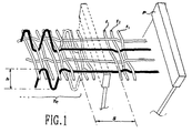
- these adjustments which will be indicated hereinafter “of motion law” and respectively “of amplitude” - are carried out by a control and adjustment device which is apt to produce a relative movement between the warp yarns and the weft yarns, such as to insert, at regular intervals, a weft yarn in an offset position (namely - as shown in fig. 1 - at a preset distance S from the fabric Te ) which, in the successive beating up, will allow to form the loops of the terry cloth.
- a control and adjustment device which is apt to produce a relative movement between the warp yarns and the weft yarns, such as to insert, at regular intervals, a weft yarn in an offset position (namely - as shown in fig. 1 - at a preset distance S from the fabric Te ) which, in the successive beating up, will allow to form the loops of the terry cloth.
- the fabric Te formed on the "weaving side” is shifted at a preset distance S, and kept there during insertion of the first two wefts t 1 and t 2 : before the beat-up of the third weft t 3 , the fabric Te is moved back to the initial position, thereby forming the loop with the regular beat-up of the weft t 3 .
- the first solution acts appropriately on the motion of the sley
- the second solution acts on the motion of the cloth holder, namely on the controlled and coordinate movement of the take-up roller and of the warp yarn guiding roller.
- Both movements are obtained by means of an electromechanical device, which receives the motion from the main shaft of the loom and transmits it to the members concerned through leverages, whose reciprocal engagement is preset by means of low-power actuators.
- EP-A-534.403 in the name of Somet Società Meccanica Tessile S.p.A., the contents of which may be used as reference for a better understanding of the present description.
- Said device comprises first mechanical members, in the form of cam means, to determine the law of the successive cyclic movements of the cloth holder, and second mechanical members, in the form of levers of different length, apt to determine the amplitude of the movement and thus the height of the terry loop.
- Such a device though apt to satisfactorily overcome many of the drawbacks of prior art, allows an automatic adjustment of the amplitude (that is, by using electromagnetically controlled mechanisms) only between three distinct values, one of them being a naught value. It is possible to preset intermediate values of amplitude, or differing from the three predermined values, only by performing manual operations on the kinematic mechanism, in order to change the position of a lever end inside an eyelet.
- EP 518.809 discloses a terry loop forming device according to the preamble of claim 1, where an articulated quadrilateral mechanism is provided and an actuating device is apt to change the length of a lever of said mechanism so as to adjust the amplitude of the motion.
- DE4432452 discloses a terry-loop-forming device where a single drive is used to determine the motion law and the amplitude of the loop-forming movement.
- the scope of the present invention is thus to solve also these further inconveniences of prior art, by supplying an adjustment device to control the cyclic movement of a cloth holder in a terry loom, which allows:
- the device to form terry loops is of the type comprising a drive shaft for transmission of a main rotary movement, and an outlet lever caused to rotate with an oscillating movement, between these two elements there being provided first mechanical members to determine the motion law and second mechanical members to adjust the amplitude of said oscillating movement in which actuating means are apt to change the geometrical position of a hinge of a kinematic chain of said second members, so that a specific transmission ratio and thus a given loop height may correspond to each of the geometrical positions taken up by said hinge.
- Fig. 1 is a diagrammatic perspective view of the weaving zone, illustrating the main parameters to form the loop in a terry cloth;
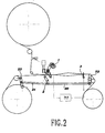
- Fig. 2 is a diagrammatic side elevation view of the main structure of the loom, into which is inserted the device according to the invention
- Figs. 3A and 3B are diagrammatic side elevation views of the device according to the invention, in a first working position for two different rotation angles of the drive shaft of the device;
- Figs. 4A and 4B are diagrammatic side elevation views of the device according to the invention, in a second working position for two different rotation angles of the drive shaft of the device.
- a main motor M1 of the weaving loom is mechanically connected in synchronism both with the sley 3 and with a drive shaft 1 of the device for terry loop formation.
- cams 4a and 4b (figs. 3A-4B) having a profile apt to determine the motion law for terry loop formation.
- said motion law for instance, modify the number of weft yarns being inserted before completion of the loop - said cams 4a and 4b can be easily replaced.
- the cams 4a and 4b transmit the motion to a rocking lever 5, which bears onto said cams by means of rollers 5a and 5b respectively, and which is pivoted in 5c. Having bound the lever 5 in the two rotation senses, there is no need to adopt any precautions (such as return springs) in order to keep the contact between the rollers 5a, 5b, and the cam surfaces 4a, 4b.
- the end of the rocking lever 5 has an eyelet 5d, of suitable length, into which is apt to freely slide a pin 6 fixed to a hinge forming part of an inlet side of an articulated quadrilateral kinematic mechanism.
- Said kinematic mechanism consists of an inlet rod 7, a connection rod 8 and an outlet lever 2.
- the connection rod 8 is pivoted, on one side, by means of the intermediate hinge-pin 6 to the inlet rod 7 and, on the other side, by means of another intermediate hinge 9 to the outlet lever 2.
- the outlet lever 2 oscillating about a first base hinge positioned in the fixed point J 1 , is the outlet lever of the terry loop formation device, since its end 2a is connected to rods 20 and 21 moving, respectively, the front cloth holder 22 and the warp yarn guiding roller 23.
- the inlet rod 7 is hinged at its other end onto a second base hinge 10 fixed to a shifting member.
- said member is in the form of an adjusting lever 11, hinged in a fixed axis J 2 and comprising a sector gear 12 extending over a circumferential path of a certain diameter and length.
- the sector gear 12 engages with a pinion 13 in the form of a worm screw, controlled by means of an auxiliary driving motor M2.
- the coupling between the worm screw 13 and the sector gear 12 forms an irreversible transmission: this represents an advantage, it being sufficient for the motor M2 to transmit a control only during adjustment, while it is no longer necessary for said motor to transmit any torque in steady running conditions, since the position of the shifting member 11 remains unvaried due to irreversibility of the coupling. It is thus evident that the auxiliary motor M2 can also have a low power and limited performances.
- the auxiliary motor M2 allows to change the angular position of the shifting member or adjusting lever 11 and thus the position of the second base hinge 10 which forms part of the articulated quadrilateral of apexes 10-6-9-J 1 . Consequently, also the transmission ratio between the inlet rod 7 and the outlet lever 2 is substantially modified: this allows to vary the amplitude of the oscillating movement transmitted, through the articulated quadrilateral mechanism, from the rocking lever 5 to the outlet lever 2.
- the motor M2 is preferably provided with an encoder allowing a microprocessor to detect the exact position of the adjusting lever 11, so as to preset the proper weaving program and that of terry loop formation.
- the inlet rod 7 and the connection rod 8 have the same length.
- the adjusting lever 11 (figs. 4A and 4B) in which the second movable base hinge 10 perfectly overlaps the intermediate hinge 9: in this condition, the motion of the rocking lever 5 is transmitted to the two rods 7 and 8, which oscillate together without any motion being transmitted to the outlet lever 2 which keeps motionless.
- no oscillating motion is transmitted by the device according to the invention to the cloth holder of the loom, thereby obtaining working conditions in which no terry loop is formed.
- the device according to the present invention it is thus possibile to continuously vary the amplitude of the oscillating movement allowing to form the terry loops, from a naught value corresponding to the normal working conditions of the loom, up to a maximum value determined by the dimensions of the elements of the aforedescribed kinematic chain.
- the device according to the present invention is extremely simple and consists of a comparatively small number of elements; it is easy to operate and requires a positive action of the auxiliary motor M2 only during adjustment, the shifting member 11 remaining motionless in a steady working condition; it allows, in a fully automatic way, to continuously vary the amplitude of the oscillating movement, starting from a naught value, without having to make use of ratchet gears or other mechanisms having to be disconnected.
- the shifting member instead of being in the form of an adjusting lever 11, could be in the form of a toothed sliding cursor apt to shift the hinge 10 along a rectilinear path, instead of a circumferential path.
Abstract
Description
- The present invention concerns a device and a method to control and adjust the members which allow to form the loops in terry looms. In particular, it concerns a device of the aforementioned type, which allows to easily carry out wide adjustments of the motion laws for the rotary oscillating movements of the take-up roller and for the coordinate alternate translatory movements of the warp yarn guiding roller, which cause the forming of terry loops.
- As known, in modern weaving looms there is the need to obtain the maximun flexibility and possibility of adjustment with the minimum manual work on the part of the operators. Particularly in weaving looms which provide for the possibility to weave terry cloths, it is necessary to be able to quickly and easily change both the distance between each terry loop in the cloth (typically, one loop every three or four beatings up of the loom: so-called "3/1 loop" and, respectively, "4/1 loop") and the height of the loop (shown by h in fig. 1) in respect of the basic terry cloth.
- According to the most recent known technique, these adjustments - which will be indicated hereinafter "of motion law" and respectively "of amplitude" - are carried out by a control and adjustment device which is apt to produce a relative movement between the warp yarns and the weft yarns, such as to insert, at regular intervals, a weft yarn in an offset position (namely - as shown in fig. 1 - at a preset distance S from the fabric Te) which, in the successive beating up, will allow to form the loops of the terry cloth.
- Said relative movement can be obtained with two different methods, which are briefly illustrated hereunder with reference to a "3/1 loop" terry cloth.
- According to a first solution, one modifies the beating up point of the reed P, so that the first two wefts t1 and t2 are left at the preset distance S: in the beat-up of the third weft t3 the reed P forms the wanted loop by performing the full stroke.
- According to another solution, the fabric Te formed on the "weaving side" is shifted at a preset distance S, and kept there during insertion of the first two wefts t1 and t2: before the beat-up of the third weft t3, the fabric Te is moved back to the initial position, thereby forming the loop with the regular beat-up of the weft t3.
- In other words, the first solution acts appropriately on the motion of the sley, while the second solution acts on the motion of the cloth holder, namely on the controlled and coordinate movement of the take-up roller and of the warp yarn guiding roller.
- Both movements are obtained by means of an electromechanical device, which receives the motion from the main shaft of the loom and transmits it to the members concerned through leverages, whose reciprocal engagement is preset by means of low-power actuators.
- A device of this type is widely illustrated EP-A-534.403, in the name of Somet Società Meccanica Tessile S.p.A., the contents of which may be used as reference for a better understanding of the present description.
- Said device comprises first mechanical members, in the form of cam means, to determine the law of the successive cyclic movements of the cloth holder, and second mechanical members, in the form of levers of different length, apt to determine the amplitude of the movement and thus the height of the terry loop.
- Such a device, though apt to satisfactorily overcome many of the drawbacks of prior art, allows an automatic adjustment of the amplitude (that is, by using electromagnetically controlled mechanisms) only between three distinct values, one of them being a naught value. It is possible to preset intermediate values of amplitude, or differing from the three predermined values, only by performing manual operations on the kinematic mechanism, in order to change the position of a lever end inside an eyelet.
- Device for the continuous adjustment of similar kinematic mechanisms forming part of this field of technique are known from EP-298.454, EP-350.446, and EP-768.407.
- Nevertheless, all these systems are complicated and thus scarcely reliable; they involve the use of a plurality of members performing relative movements one in respect of the other, which give rise to undesired frictions and overheating; they require a constant active control on an adjustment motor; they involve the use of ratchet gears or other disconnectable mechanisms, to stop the action of the device when the loom must work in normal conditions without having to form a terry loop.
- EP 518.809 discloses a terry loop forming device according to the preamble of claim 1, where an articulated quadrilateral mechanism is provided and an actuating device is apt to change the length of a lever of said mechanism so as to adjust the amplitude of the motion.
DE4432452 discloses a terry-loop-forming device where a single drive is used to determine the motion law and the amplitude of the loop-forming movement. - The scope of the present invention is thus to solve also these further inconveniences of prior art, by supplying an adjustment device to control the cyclic movement of a cloth holder in a terry loom, which allows:
- to continuously vary, in an extremely simple manner, the amplitude of the movement up to reaching naught values of the amplitude for a normal working condition of the loom; and
- to actively operate with a shifting member only during adjustment, said member remaining in a fixed position during normal working in steady conditions;
- all this being achieved with a minimum amount of elements of the kinematic mechanism and by eliminating as far as possible the use of high-friction sliding couplings, so as to provide a device apt to work in a continuous and reliable manner, while requiring very little maintenance.
- said objects are reached by means of a device and method as described in the accompanying claims.
- In short, the device to form terry loops according to the present invention is of the type comprising a drive shaft for transmission of a main rotary movement, and an outlet lever caused to rotate with an oscillating movement, between these two elements there being provided first mechanical members to determine the motion law and second mechanical members to adjust the amplitude of said oscillating movement in which actuating means are apt to change the geometrical position of a hinge of a kinematic chain of said second members, so that a specific transmission ratio and thus a given loop height may correspond to each of the geometrical positions taken up by said hinge.
- Further characteristics and advantages of the device according to the present invention will anyhow be more evident from the following detailed description of a preferred embodiment thereof, given by way of example and illustrated on the accompanying drawings, in which:
- Fig. 1 is a diagrammatic perspective view of the weaving zone, illustrating the main parameters to form the loop in a terry cloth;
- Fig. 2 is a diagrammatic side elevation view of the main structure of the loom, into which is inserted the device according to the invention;
- . Figs. 3A and 3B are diagrammatic side elevation views of the device according to the invention, in a first working position for two different rotation angles of the drive shaft of the device; and
- Figs. 4A and 4B are diagrammatic side elevation views of the device according to the invention, in a second working position for two different rotation angles of the drive shaft of the device.
- With reference to fig. 2, a main motor M1 of the weaving loom is mechanically connected in synchronism both with the
sley 3 and with a drive shaft 1 of the device for terry loop formation. - On said drive or inlet shaft 1 there are keyed two
conjugate cams cams - The
cams lever 5, which bears onto said cams by means ofrollers lever 5 in the two rotation senses, there is no need to adopt any precautions (such as return springs) in order to keep the contact between therollers cam surfaces - According to the invention, the end of the rocking
lever 5 has aneyelet 5d, of suitable length, into which is apt to freely slide apin 6 fixed to a hinge forming part of an inlet side of an articulated quadrilateral kinematic mechanism. - Said kinematic mechanism consists of an inlet rod 7, a
connection rod 8 and anoutlet lever 2. Theconnection rod 8 is pivoted, on one side, by means of the intermediate hinge-pin 6 to the inlet rod 7 and, on the other side, by means of another intermediate hinge 9 to theoutlet lever 2. - The
outlet lever 2, oscillating about a first base hinge positioned in the fixed point J1, is the outlet lever of the terry loop formation device, since itsend 2a is connected torods front cloth holder 22 and the warpyarn guiding roller 23. - Whereas, the inlet rod 7 is hinged at its other end onto a
second base hinge 10 fixed to a shifting member. In the embodiment shown, said member is in the form of an adjustinglever 11, hinged in a fixed axis J2 and comprising asector gear 12 extending over a circumferential path of a certain diameter and length. - The
sector gear 12 engages with apinion 13 in the form of a worm screw, controlled by means of an auxiliary driving motor M2. The coupling between theworm screw 13 and thesector gear 12 forms an irreversible transmission: this represents an advantage, it being sufficient for the motor M2 to transmit a control only during adjustment, while it is no longer necessary for said motor to transmit any torque in steady running conditions, since the position of the shiftingmember 11 remains unvaried due to irreversibility of the coupling. It is thus evident that the auxiliary motor M2 can also have a low power and limited performances. - As can be understood, also by referring to the drawings, the auxiliary motor M2 allows to change the angular position of the shifting member or adjusting
lever 11 and thus the position of thesecond base hinge 10 which forms part of the articulated quadrilateral of apexes 10-6-9-J1. Consequently, also the transmission ratio between the inlet rod 7 and theoutlet lever 2 is substantially modified: this allows to vary the amplitude of the oscillating movement transmitted, through the articulated quadrilateral mechanism, from the rockinglever 5 to theoutlet lever 2. - As can be seen from figs. 3A and 3B (which illustrate two different angular positions, α1 and α2 respectively, of the drive shaft 1) the oscillation of the
rocking lever 5, controlled by thecams pin 6 and theeyelet 5d, and in turn to theoutlet lever 2 with a transmission ratio determined by the geometry of the articulated quadrilateral mechanism, namely by the position of thesecond base hinge 10. - - The motor M2 is preferably provided with an encoder allowing a microprocessor to detect the exact position of the adjusting
lever 11, so as to preset the proper weaving program and that of terry loop formation. - According to a preferred embodiment of the invention, the inlet rod 7 and the
connection rod 8 have the same length. In this case, it is possible to find a position of the adjusting lever 11 (figs. 4A and 4B) in which the second movable base hinge 10 perfectly overlaps the intermediate hinge 9: in this condition, the motion of the rockinglever 5 is transmitted to the tworods 7 and 8, which oscillate together without any motion being transmitted to theoutlet lever 2 which keeps motionless. Evidently, in these conditions, no oscillating motion is transmitted by the device according to the invention to the cloth holder of the loom, thereby obtaining working conditions in which no terry loop is formed. - With the device according to the present invention it is thus possibile to continuously vary the amplitude of the oscillating movement allowing to form the terry loops, from a naught value corresponding to the normal working conditions of the loom, up to a maximum value determined by the dimensions of the elements of the aforedescribed kinematic chain.
- All the objects set forth earlier in the description have thus been achieved. In fact, the device according to the present invention is extremely simple and consists of a comparatively small number of elements; it is easy to operate and requires a positive action of the auxiliary motor M2 only during adjustment, the shifting
member 11 remaining motionless in a steady working condition; it allows, in a fully automatic way, to continuously vary the amplitude of the oscillating movement, starting from a naught value, without having to make use of ratchet gears or other mechanisms having to be disconnected. - It is anyhow understood that the invention is not limited to the particular embodiment described heretofore, which merely represents a non-limiting example of its scope, but many variants can be introduced therein, all within the reach of a person skilled in the art, without thereby departing from the scope of the present invention.
- For example - if it were deemed preferable for the specific working conditions - the shifting member, instead of being in the form of an adjusting
lever 11, could be in the form of a toothed sliding cursor apt to shift thehinge 10 along a rectilinear path, instead of a circumferential path. - Likewise, it is not strictly necessary for the
eyelet 5d to be engaged by the intermediate hinge-pin 6, between the inlet rod 7 and the connectingrod 8, it being sufficient for the motion of the rockinglever 5 to be transmitted to the inlet rod 7.
Claims (9)
- Device to control and adjust, in terry looms, the movements of the take-up roller and of the warp yarn guiding roller which cause the forming of terry loops - of the type comprising a drive shaft (1), connected to a main drive of the loom, and an outlet lever (2) apt to impart a cyclic movement to said take-up roller and/or guiding roller, between said shaft (1) and said lever (2) being provided first mechanical members (4a, 4b, 5) to determine the motion law and a kinematic chain comprising at least a quadrilateral mechanism (7, 8, 2), characterised in that it also comprises actuating means (11, 13 M2) apt to change the geometrical position of a movable base hinge (10) of said quadrilateral mechanism to adjust the transmission ratio between said shaft (1) and said lever (2).
- Device as in claim 1), wherein said quadrilateral mechanism comprises an inlet rod (7) controlled by said first mechanical members (4a, 4b, 5), a connection rod (8), and an outlet rod forming said outlet lever (2) or being integral therewith, said movable base hinge (10) coinciding with the base hinge of one of said inlet or outlet rods.
- Device as in claim 2), wherein said movable hinge is the base hinge (10) of said inlet rod (7).
- Device as in claims 1), 2) or 3), wherein said actuating means comprise an electric motor (M2) apt to control a shifting member to shift said movable hinge (10).
- Device as in claim 4), wherein said shifting member is in the form of an oscillating adjusting lever (11) comprising a sector gear (12) engaged with a corresponding pinion (13) of said electric motor (M2).
- Device as in any one of claims 3) to 5), wherein said inlet rod (7) and said connection rod (8) are of equal length, so that a position of the movable hinge (10) can be determined in correspondence of which the outlet lever (2) keeps motionless during motion of the first mechanical members.
- Device as in any one of the previous claims, wherein said first mechanical members include of a rocking lever (5), controlled by cam means (4a, 4b) and comprising an eyelet (5d) into which is apt to freely slide a pin (6) fixed to the inlet rod (7) of said articulated quadrilateral mechanism.
- Method to control and adjust, in a terry loom, the movements of the take-up roller and of the warp yarn guiding roller which cause the forming of terry loops - comprising to provide a terry loop forming device including first mechanical members (4a, 4b, 5) to determine the motion law and a quadrilateral mechanism (7, 8, 2), characterised in that the amplitude of said movements which cause the forming of terry loops is varied shifting the position of a movable base hinge (10) of said quadrilateral mechanism (7, 8, 2).
- Method as in claim 8), wherein the naught value of said oscillation amplitude, namely the loom working condition in which no terry loop is formed, is obtained by causing the position of said movable base hinge (10) to coincide with the position of the not adjacent intermediate hinge (9) of said quadrilateral mechanism (7, 8, 2).
Applications Claiming Priority (2)
| Application Number | Priority Date | Filing Date | Title |
|---|---|---|---|
| IT2000MI000436A IT1317119B1 (en) | 2000-03-07 | 2000-03-07 | COMMAND AND REGULATION DEVICE FOR THE FORMATION OF SPONGE-TYPE WEAVING CURLS |
| ITMI000436 | 2000-03-07 |
Publications (2)
| Publication Number | Publication Date |
|---|---|
| EP1132509A1 EP1132509A1 (en) | 2001-09-12 |
| EP1132509B1 true EP1132509B1 (en) | 2005-04-06 |
Family
ID=11444333
Family Applications (1)
| Application Number | Title | Priority Date | Filing Date |
|---|---|---|---|
| EP01104353A Expired - Lifetime EP1132509B1 (en) | 2000-03-07 | 2001-02-23 | Control and adjustment device to form terry loops in terry looms and method thereof |
Country Status (5)
| Country | Link |
|---|---|
| EP (1) | EP1132509B1 (en) |
| AT (1) | ATE292702T1 (en) |
| DE (1) | DE60109842T2 (en) |
| ES (1) | ES2240256T3 (en) |
| IT (1) | IT1317119B1 (en) |
Families Citing this family (2)
| Publication number | Priority date | Publication date | Assignee | Title |
|---|---|---|---|---|
| EP1304406A1 (en) * | 2001-10-19 | 2003-04-23 | Promatech S.p.A. | Control device of the motion law to form terry loops in multi-weft terry looms and method thereof |
| CN1763282B (en) * | 2005-11-10 | 2011-02-09 | 杭州纺织机械有限公司 | Novel cloth moving type fuzzing mechanism |
Family Cites Families (3)
| Publication number | Priority date | Publication date | Assignee | Title |
|---|---|---|---|---|
| US5392817A (en) * | 1991-06-11 | 1995-02-28 | Sulzer Brothers Limited | Apparatus for altering the loop length of terry cloth |
| IT1251848B (en) * | 1991-09-23 | 1995-05-26 | Somet Soc Mec Tessile | ELECTROMECHANICAL DEVICE TO COMMAND THE FORMATION MOVEMENTS OF THE CURL IN WEAVING FRAMES OF SPONGE FABRICS |
| IT1267447B1 (en) * | 1993-09-13 | 1997-02-05 | Toyoda Automatic Loom Works | PROCESS AND APPARATUS FOR THE FORMATION OF THE HAIR IN A MACHINE FOR WEAVING HAIR FABRICS. |
-
2000
- 2000-03-07 IT IT2000MI000436A patent/IT1317119B1/en active
-
2001
- 2001-02-23 DE DE60109842T patent/DE60109842T2/en not_active Expired - Lifetime
- 2001-02-23 ES ES01104353T patent/ES2240256T3/en not_active Expired - Lifetime
- 2001-02-23 EP EP01104353A patent/EP1132509B1/en not_active Expired - Lifetime
- 2001-02-23 AT AT01104353T patent/ATE292702T1/en not_active IP Right Cessation
Also Published As
| Publication number | Publication date |
|---|---|
| DE60109842T2 (en) | 2006-01-19 |
| ATE292702T1 (en) | 2005-04-15 |
| IT1317119B1 (en) | 2003-05-27 |
| ITMI20000436A1 (en) | 2001-09-07 |
| ITMI20000436A0 (en) | 2000-03-07 |
| EP1132509A1 (en) | 2001-09-12 |
| DE60109842D1 (en) | 2005-05-12 |
| ES2240256T3 (en) | 2005-10-16 |
Similar Documents
| Publication | Publication Date | Title |
|---|---|---|
| JP2975387B2 (en) | Method and apparatus for driving a reed | |
| US3889719A (en) | Weaving machine for producing terry cloth | |
| EP1132509B1 (en) | Control and adjustment device to form terry loops in terry looms and method thereof | |
| US3428095A (en) | Cloth motion in looms | |
| EP0834611B1 (en) | Device for inserting alternately-interposed wefts on a crochet galloon machine for warp weaving, and article of manufacture thus obtained | |
| GB2063933A (en) | Terry motions | |
| US3678968A (en) | Shuttleless loom | |
| US5320143A (en) | Variable pitch cylindrical cam mechanism for controlling the motion of weft insertion members in shuttleless weaving looms | |
| US4385649A (en) | Device for programmed change of position of nozzles in jet looms | |
| CN110168156A (en) | Selvedge apparatus | |
| US3752195A (en) | Loom | |
| US20020121311A1 (en) | Apparatus for the manufacture of leno fabrics | |
| EP0768402B1 (en) | Device for programming rotary dobbies in weaving machines | |
| EP0893522A1 (en) | Device to control the slotted leno heald weave mechanism in looms | |
| US4099546A (en) | Device for varying the beating-up position of the reed of a textile loom for Turkish towelling | |
| EP1251194B1 (en) | Improved programming device for rotary dobbies of weaving machines | |
| JP2718965B2 (en) | Loom beating position control device | |
| US3877492A (en) | Terry motion for looms | |
| EP0534403B1 (en) | Electromechanical device to control terry loop formation in terry looms | |
| EP3121320B1 (en) | Device for adjusting the tension of the pile warp yarns in a terrycloth weaving loom | |
| JPH11172552A (en) | Warp tension correcting method for cloth-moving pile loom | |
| EP0036897B1 (en) | Control device for reciprocating grippers in shuttleless looms | |
| JP3377166B2 (en) | Pile forming equipment | |
| US3000403A (en) | Weaving machine | |
| US3363653A (en) | Reed controlling mechanism for terry loom |
Legal Events
| Date | Code | Title | Description |
|---|---|---|---|
| PUAI | Public reference made under article 153(3) epc to a published international application that has entered the european phase |
Free format text: ORIGINAL CODE: 0009012 |
|
| AK | Designated contracting states |
Kind code of ref document: A1 Designated state(s): AT BE CH CY DE DK ES FI FR GB GR IE IT LI LU MC NL PT SE TR |
|
| AX | Request for extension of the european patent |
Free format text: AL;LT;LV;MK;RO;SI |
|
| 17P | Request for examination filed |
Effective date: 20010921 |
|
| AKX | Designation fees paid |
Free format text: AT BE CH CY DE DK ES FI FR GB GR IE IT LI LU MC NL PT SE TR |
|
| 17Q | First examination report despatched |
Effective date: 20030929 |
|
| GRAP | Despatch of communication of intention to grant a patent |
Free format text: ORIGINAL CODE: EPIDOSNIGR1 |
|
| GRAS | Grant fee paid |
Free format text: ORIGINAL CODE: EPIDOSNIGR3 |
|
| GRAA | (expected) grant |
Free format text: ORIGINAL CODE: 0009210 |
|
| AK | Designated contracting states |
Kind code of ref document: B1 Designated state(s): AT BE CH CY DE DK ES FI FR GB GR IE IT LI LU MC NL PT SE TR |
|
| PG25 | Lapsed in a contracting state [announced via postgrant information from national office to epo] |
Ref country code: FI Free format text: LAPSE BECAUSE OF FAILURE TO SUBMIT A TRANSLATION OF THE DESCRIPTION OR TO PAY THE FEE WITHIN THE PRESCRIBED TIME-LIMIT Effective date: 20050406 Ref country code: AT Free format text: LAPSE BECAUSE OF FAILURE TO SUBMIT A TRANSLATION OF THE DESCRIPTION OR TO PAY THE FEE WITHIN THE PRESCRIBED TIME-LIMIT Effective date: 20050406 Ref country code: NL Free format text: LAPSE BECAUSE OF FAILURE TO SUBMIT A TRANSLATION OF THE DESCRIPTION OR TO PAY THE FEE WITHIN THE PRESCRIBED TIME-LIMIT Effective date: 20050406 |
|
| REG | Reference to a national code |
Ref country code: GB Ref legal event code: FG4D |
|
| REG | Reference to a national code |
Ref country code: CH Ref legal event code: EP |
|
| REG | Reference to a national code |
Ref country code: IE Ref legal event code: FG4D |
|
| REF | Corresponds to: |
Ref document number: 60109842 Country of ref document: DE Date of ref document: 20050512 Kind code of ref document: P |
|
| PG25 | Lapsed in a contracting state [announced via postgrant information from national office to epo] |
Ref country code: GR Free format text: LAPSE BECAUSE OF FAILURE TO SUBMIT A TRANSLATION OF THE DESCRIPTION OR TO PAY THE FEE WITHIN THE PRESCRIBED TIME-LIMIT Effective date: 20050706 Ref country code: SE Free format text: LAPSE BECAUSE OF FAILURE TO SUBMIT A TRANSLATION OF THE DESCRIPTION OR TO PAY THE FEE WITHIN THE PRESCRIBED TIME-LIMIT Effective date: 20050706 Ref country code: DK Free format text: LAPSE BECAUSE OF FAILURE TO SUBMIT A TRANSLATION OF THE DESCRIPTION OR TO PAY THE FEE WITHIN THE PRESCRIBED TIME-LIMIT Effective date: 20050706 |
|
| REG | Reference to a national code |
Ref country code: CH Ref legal event code: NV Representative=s name: PATENTANWAELTE SCHAAD, BALASS, MENZL & PARTNER AG |
|
| PG25 | Lapsed in a contracting state [announced via postgrant information from national office to epo] |
Ref country code: PT Free format text: LAPSE BECAUSE OF FAILURE TO SUBMIT A TRANSLATION OF THE DESCRIPTION OR TO PAY THE FEE WITHIN THE PRESCRIBED TIME-LIMIT Effective date: 20050908 |
|
| NLV1 | Nl: lapsed or annulled due to failure to fulfill the requirements of art. 29p and 29m of the patents act | ||
| REG | Reference to a national code |
Ref country code: ES Ref legal event code: FG2A Ref document number: 2240256 Country of ref document: ES Kind code of ref document: T3 |
|
| PLBE | No opposition filed within time limit |
Free format text: ORIGINAL CODE: 0009261 |
|
| STAA | Information on the status of an ep patent application or granted ep patent |
Free format text: STATUS: NO OPPOSITION FILED WITHIN TIME LIMIT |
|
| PG25 | Lapsed in a contracting state [announced via postgrant information from national office to epo] |
Ref country code: IE Free format text: LAPSE BECAUSE OF NON-PAYMENT OF DUE FEES Effective date: 20060223 |
|
| PG25 | Lapsed in a contracting state [announced via postgrant information from national office to epo] |
Ref country code: MC Free format text: LAPSE BECAUSE OF NON-PAYMENT OF DUE FEES Effective date: 20060228 Ref country code: LU Free format text: LAPSE BECAUSE OF NON-PAYMENT OF DUE FEES Effective date: 20060228 |
|
| ET | Fr: translation filed | ||
| 26N | No opposition filed |
Effective date: 20060110 |
|
| REG | Reference to a national code |
Ref country code: IE Ref legal event code: MM4A |
|
| PG25 | Lapsed in a contracting state [announced via postgrant information from national office to epo] |
Ref country code: TR Free format text: LAPSE BECAUSE OF FAILURE TO SUBMIT A TRANSLATION OF THE DESCRIPTION OR TO PAY THE FEE WITHIN THE PRESCRIBED TIME-LIMIT Effective date: 20050406 |
|
| PG25 | Lapsed in a contracting state [announced via postgrant information from national office to epo] |
Ref country code: CY Free format text: LAPSE BECAUSE OF FAILURE TO SUBMIT A TRANSLATION OF THE DESCRIPTION OR TO PAY THE FEE WITHIN THE PRESCRIBED TIME-LIMIT Effective date: 20050406 |
|
| PGFP | Annual fee paid to national office [announced via postgrant information from national office to epo] |
Ref country code: ES Payment date: 20090217 Year of fee payment: 9 |
|
| PGFP | Annual fee paid to national office [announced via postgrant information from national office to epo] |
Ref country code: GB Payment date: 20090211 Year of fee payment: 9 |
|
| PGFP | Annual fee paid to national office [announced via postgrant information from national office to epo] |
Ref country code: FR Payment date: 20090211 Year of fee payment: 9 |
|
| GBPC | Gb: european patent ceased through non-payment of renewal fee |
Effective date: 20100223 |
|
| REG | Reference to a national code |
Ref country code: FR Ref legal event code: ST Effective date: 20101029 |
|
| PG25 | Lapsed in a contracting state [announced via postgrant information from national office to epo] |
Ref country code: FR Free format text: LAPSE BECAUSE OF NON-PAYMENT OF DUE FEES Effective date: 20100301 |
|
| PG25 | Lapsed in a contracting state [announced via postgrant information from national office to epo] |
Ref country code: GB Free format text: LAPSE BECAUSE OF NON-PAYMENT OF DUE FEES Effective date: 20100223 |
|
| REG | Reference to a national code |
Ref country code: ES Ref legal event code: FD2A Effective date: 20110407 |
|
| PG25 | Lapsed in a contracting state [announced via postgrant information from national office to epo] |
Ref country code: ES Free format text: LAPSE BECAUSE OF NON-PAYMENT OF DUE FEES Effective date: 20110328 |
|
| PG25 | Lapsed in a contracting state [announced via postgrant information from national office to epo] |
Ref country code: ES Free format text: LAPSE BECAUSE OF NON-PAYMENT OF DUE FEES Effective date: 20100224 |
|
| PGFP | Annual fee paid to national office [announced via postgrant information from national office to epo] |
Ref country code: DE Payment date: 20130219 Year of fee payment: 13 |
|
| REG | Reference to a national code |
Ref country code: DE Ref legal event code: R119 Ref document number: 60109842 Country of ref document: DE |
|
| REG | Reference to a national code |
Ref country code: DE Ref legal event code: R119 Ref document number: 60109842 Country of ref document: DE Effective date: 20140902 |
|
| PG25 | Lapsed in a contracting state [announced via postgrant information from national office to epo] |
Ref country code: DE Free format text: LAPSE BECAUSE OF NON-PAYMENT OF DUE FEES Effective date: 20140902 |
|
| PGFP | Annual fee paid to national office [announced via postgrant information from national office to epo] |
Ref country code: CH Payment date: 20150218 Year of fee payment: 15 |
|
| REG | Reference to a national code |
Ref country code: CH Ref legal event code: PL |
|
| PG25 | Lapsed in a contracting state [announced via postgrant information from national office to epo] |
Ref country code: CH Free format text: LAPSE BECAUSE OF NON-PAYMENT OF DUE FEES Effective date: 20160229 Ref country code: LI Free format text: LAPSE BECAUSE OF NON-PAYMENT OF DUE FEES Effective date: 20160229 |
|
| PGFP | Annual fee paid to national office [announced via postgrant information from national office to epo] |
Ref country code: IT Payment date: 20180124 Year of fee payment: 18 Ref country code: BE Payment date: 20180216 Year of fee payment: 18 |
|
| REG | Reference to a national code |
Ref country code: BE Ref legal event code: MM Effective date: 20190228 |
|
| PG25 | Lapsed in a contracting state [announced via postgrant information from national office to epo] |
Ref country code: IT Free format text: LAPSE BECAUSE OF NON-PAYMENT OF DUE FEES Effective date: 20190223 Ref country code: BE Free format text: LAPSE BECAUSE OF NON-PAYMENT OF DUE FEES Effective date: 20190228 |