EP1132490B1 - Kolben mit einem metallischen verbundwerkstoff - Google Patents
Kolben mit einem metallischen verbundwerkstoff Download PDFInfo
- Publication number
- EP1132490B1 EP1132490B1 EP20000951939 EP00951939A EP1132490B1 EP 1132490 B1 EP1132490 B1 EP 1132490B1 EP 20000951939 EP20000951939 EP 20000951939 EP 00951939 A EP00951939 A EP 00951939A EP 1132490 B1 EP1132490 B1 EP 1132490B1
- Authority
- EP
- European Patent Office
- Prior art keywords
- reinforcements
- metal
- matrix
- matrix composite
- composite
- Prior art date
- Legal status (The legal status is an assumption and is not a legal conclusion. Google has not performed a legal analysis and makes no representation as to the accuracy of the status listed.)
- Expired - Lifetime
Links
Images


Classifications
-
- B—PERFORMING OPERATIONS; TRANSPORTING
- B22—CASTING; POWDER METALLURGY
- B22D—CASTING OF METALS; CASTING OF OTHER SUBSTANCES BY THE SAME PROCESSES OR DEVICES
- B22D18/00—Pressure casting; Vacuum casting
- B22D18/02—Pressure casting making use of mechanical pressure devices, e.g. cast-forging
-
- B—PERFORMING OPERATIONS; TRANSPORTING
- B22—CASTING; POWDER METALLURGY
- B22D—CASTING OF METALS; CASTING OF OTHER SUBSTANCES BY THE SAME PROCESSES OR DEVICES
- B22D19/00—Casting in, on, or around objects which form part of the product
- B22D19/0009—Cylinders, pistons
- B22D19/0027—Cylinders, pistons pistons
-
- B—PERFORMING OPERATIONS; TRANSPORTING
- B22—CASTING; POWDER METALLURGY
- B22D—CASTING OF METALS; CASTING OF OTHER SUBSTANCES BY THE SAME PROCESSES OR DEVICES
- B22D19/00—Casting in, on, or around objects which form part of the product
- B22D19/14—Casting in, on, or around objects which form part of the product the objects being filamentary or particulate in form
-
- B—PERFORMING OPERATIONS; TRANSPORTING
- B22—CASTING; POWDER METALLURGY
- B22F—WORKING METALLIC POWDER; MANUFACTURE OF ARTICLES FROM METALLIC POWDER; MAKING METALLIC POWDER; APPARATUS OR DEVICES SPECIALLY ADAPTED FOR METALLIC POWDER
- B22F1/00—Metallic powder; Treatment of metallic powder, e.g. to facilitate working or to improve properties
- B22F1/06—Metallic powder characterised by the shape of the particles
- B22F1/062—Fibrous particles
-
- C—CHEMISTRY; METALLURGY
- C22—METALLURGY; FERROUS OR NON-FERROUS ALLOYS; TREATMENT OF ALLOYS OR NON-FERROUS METALS
- C22C—ALLOYS
- C22C38/00—Ferrous alloys, e.g. steel alloys
- C22C38/02—Ferrous alloys, e.g. steel alloys containing silicon
-
- C—CHEMISTRY; METALLURGY
- C22—METALLURGY; FERROUS OR NON-FERROUS ALLOYS; TREATMENT OF ALLOYS OR NON-FERROUS METALS
- C22C—ALLOYS
- C22C38/00—Ferrous alloys, e.g. steel alloys
- C22C38/06—Ferrous alloys, e.g. steel alloys containing aluminium
-
- C—CHEMISTRY; METALLURGY
- C22—METALLURGY; FERROUS OR NON-FERROUS ALLOYS; TREATMENT OF ALLOYS OR NON-FERROUS METALS
- C22C—ALLOYS
- C22C38/00—Ferrous alloys, e.g. steel alloys
- C22C38/18—Ferrous alloys, e.g. steel alloys containing chromium
-
- C—CHEMISTRY; METALLURGY
- C22—METALLURGY; FERROUS OR NON-FERROUS ALLOYS; TREATMENT OF ALLOYS OR NON-FERROUS METALS
- C22C—ALLOYS
- C22C49/00—Alloys containing metallic or non-metallic fibres or filaments
- C22C49/14—Alloys containing metallic or non-metallic fibres or filaments characterised by the fibres or filaments
-
- F—MECHANICAL ENGINEERING; LIGHTING; HEATING; WEAPONS; BLASTING
- F02—COMBUSTION ENGINES; HOT-GAS OR COMBUSTION-PRODUCT ENGINE PLANTS
- F02B—INTERNAL-COMBUSTION PISTON ENGINES; COMBUSTION ENGINES IN GENERAL
- F02B23/00—Other engines characterised by special shape or construction of combustion chambers to improve operation
- F02B23/02—Other engines characterised by special shape or construction of combustion chambers to improve operation with compression ignition
- F02B23/06—Other engines characterised by special shape or construction of combustion chambers to improve operation with compression ignition the combustion space being arranged in working piston
- F02B23/0672—Omega-piston bowl, i.e. the combustion space having a central projection pointing towards the cylinder head and the surrounding wall being inclined towards the cylinder center axis
-
- F—MECHANICAL ENGINEERING; LIGHTING; HEATING; WEAPONS; BLASTING
- F02—COMBUSTION ENGINES; HOT-GAS OR COMBUSTION-PRODUCT ENGINE PLANTS
- F02F—CYLINDERS, PISTONS OR CASINGS, FOR COMBUSTION ENGINES; ARRANGEMENTS OF SEALINGS IN COMBUSTION ENGINES
- F02F3/00—Pistons
- F02F3/02—Pistons having means for accommodating or controlling heat expansion
- F02F3/04—Pistons having means for accommodating or controlling heat expansion having expansion-controlling inserts
- F02F3/045—Pistons having means for accommodating or controlling heat expansion having expansion-controlling inserts the inserts being located in the crown
-
- B—PERFORMING OPERATIONS; TRANSPORTING
- B22—CASTING; POWDER METALLURGY
- B22F—WORKING METALLIC POWDER; MANUFACTURE OF ARTICLES FROM METALLIC POWDER; MAKING METALLIC POWDER; APPARATUS OR DEVICES SPECIALLY ADAPTED FOR METALLIC POWDER
- B22F3/00—Manufacture of workpieces or articles from metallic powder characterised by the manner of compacting or sintering; Apparatus specially adapted therefor ; Presses and furnaces
- B22F3/24—After-treatment of workpieces or articles
- B22F2003/248—Thermal after-treatment
-
- F—MECHANICAL ENGINEERING; LIGHTING; HEATING; WEAPONS; BLASTING
- F05—INDEXING SCHEMES RELATING TO ENGINES OR PUMPS IN VARIOUS SUBCLASSES OF CLASSES F01-F04
- F05C—INDEXING SCHEME RELATING TO MATERIALS, MATERIAL PROPERTIES OR MATERIAL CHARACTERISTICS FOR MACHINES, ENGINES OR PUMPS OTHER THAN NON-POSITIVE-DISPLACEMENT MACHINES OR ENGINES
- F05C2201/00—Metals
- F05C2201/02—Light metals
- F05C2201/021—Aluminium
-
- F—MECHANICAL ENGINEERING; LIGHTING; HEATING; WEAPONS; BLASTING
- F05—INDEXING SCHEMES RELATING TO ENGINES OR PUMPS IN VARIOUS SUBCLASSES OF CLASSES F01-F04
- F05C—INDEXING SCHEME RELATING TO MATERIALS, MATERIAL PROPERTIES OR MATERIAL CHARACTERISTICS FOR MACHINES, ENGINES OR PUMPS OTHER THAN NON-POSITIVE-DISPLACEMENT MACHINES OR ENGINES
- F05C2251/00—Material properties
- F05C2251/04—Thermal properties
- F05C2251/042—Expansivity
-
- F—MECHANICAL ENGINEERING; LIGHTING; HEATING; WEAPONS; BLASTING
- F05—INDEXING SCHEMES RELATING TO ENGINES OR PUMPS IN VARIOUS SUBCLASSES OF CLASSES F01-F04
- F05C—INDEXING SCHEME RELATING TO MATERIALS, MATERIAL PROPERTIES OR MATERIAL CHARACTERISTICS FOR MACHINES, ENGINES OR PUMPS OTHER THAN NON-POSITIVE-DISPLACEMENT MACHINES OR ENGINES
- F05C2253/00—Other material characteristics; Treatment of material
- F05C2253/16—Fibres
-
- Y—GENERAL TAGGING OF NEW TECHNOLOGICAL DEVELOPMENTS; GENERAL TAGGING OF CROSS-SECTIONAL TECHNOLOGIES SPANNING OVER SEVERAL SECTIONS OF THE IPC; TECHNICAL SUBJECTS COVERED BY FORMER USPC CROSS-REFERENCE ART COLLECTIONS [XRACs] AND DIGESTS
- Y02—TECHNOLOGIES OR APPLICATIONS FOR MITIGATION OR ADAPTATION AGAINST CLIMATE CHANGE
- Y02T—CLIMATE CHANGE MITIGATION TECHNOLOGIES RELATED TO TRANSPORTATION
- Y02T10/00—Road transport of goods or passengers
- Y02T10/10—Internal combustion engine [ICE] based vehicles
- Y02T10/12—Improving ICE efficiencies
-
- Y—GENERAL TAGGING OF NEW TECHNOLOGICAL DEVELOPMENTS; GENERAL TAGGING OF CROSS-SECTIONAL TECHNOLOGIES SPANNING OVER SEVERAL SECTIONS OF THE IPC; TECHNICAL SUBJECTS COVERED BY FORMER USPC CROSS-REFERENCE ART COLLECTIONS [XRACs] AND DIGESTS
- Y10—TECHNICAL SUBJECTS COVERED BY FORMER USPC
- Y10T—TECHNICAL SUBJECTS COVERED BY FORMER US CLASSIFICATION
- Y10T428/00—Stock material or miscellaneous articles
- Y10T428/12—All metal or with adjacent metals
- Y10T428/12486—Laterally noncoextensive components [e.g., embedded, etc.]
-
- Y—GENERAL TAGGING OF NEW TECHNOLOGICAL DEVELOPMENTS; GENERAL TAGGING OF CROSS-SECTIONAL TECHNOLOGIES SPANNING OVER SEVERAL SECTIONS OF THE IPC; TECHNICAL SUBJECTS COVERED BY FORMER USPC CROSS-REFERENCE ART COLLECTIONS [XRACs] AND DIGESTS
- Y10—TECHNICAL SUBJECTS COVERED BY FORMER USPC
- Y10T—TECHNICAL SUBJECTS COVERED BY FORMER US CLASSIFICATION
- Y10T428/00—Stock material or miscellaneous articles
- Y10T428/12—All metal or with adjacent metals
- Y10T428/12493—Composite; i.e., plural, adjacent, spatially distinct metal components [e.g., layers, joint, etc.]
- Y10T428/12736—Al-base component
- Y10T428/1275—Next to Group VIII or IB metal-base component
- Y10T428/12757—Fe
-
- Y—GENERAL TAGGING OF NEW TECHNOLOGICAL DEVELOPMENTS; GENERAL TAGGING OF CROSS-SECTIONAL TECHNOLOGIES SPANNING OVER SEVERAL SECTIONS OF THE IPC; TECHNICAL SUBJECTS COVERED BY FORMER USPC CROSS-REFERENCE ART COLLECTIONS [XRACs] AND DIGESTS
- Y10—TECHNICAL SUBJECTS COVERED BY FORMER USPC
- Y10T—TECHNICAL SUBJECTS COVERED BY FORMER US CLASSIFICATION
- Y10T428/00—Stock material or miscellaneous articles
- Y10T428/12—All metal or with adjacent metals
- Y10T428/12493—Composite; i.e., plural, adjacent, spatially distinct metal components [e.g., layers, joint, etc.]
- Y10T428/12771—Transition metal-base component
- Y10T428/12861—Group VIII or IB metal-base component
- Y10T428/12951—Fe-base component
- Y10T428/12958—Next to Fe-base component
-
- Y—GENERAL TAGGING OF NEW TECHNOLOGICAL DEVELOPMENTS; GENERAL TAGGING OF CROSS-SECTIONAL TECHNOLOGIES SPANNING OVER SEVERAL SECTIONS OF THE IPC; TECHNICAL SUBJECTS COVERED BY FORMER USPC CROSS-REFERENCE ART COLLECTIONS [XRACs] AND DIGESTS
- Y10—TECHNICAL SUBJECTS COVERED BY FORMER USPC
- Y10T—TECHNICAL SUBJECTS COVERED BY FORMER US CLASSIFICATION
- Y10T428/00—Stock material or miscellaneous articles
- Y10T428/249921—Web or sheet containing structurally defined element or component
- Y10T428/249924—Noninterengaged fiber-containing paper-free web or sheet which is not of specified porosity
- Y10T428/249927—Fiber embedded in a metal matrix
Definitions
- the present invention relates to a piston with a metal matrix composite, including a light metal alloy, e.g., aluminum alloy, magnesium alloy, etc., as a matrix (base metal) and a method to create it.
- a light metal alloy e.g., aluminum alloy, magnesium alloy, etc.
- EP 0 867 517 a composite with an aluminum matrix and a method for production is known.
- EP 0 867 517 is seen as the closest prior art.
- a metal matrix composite (abbrev. as MMC) may be used in the case where required characteristics cannot be obtained with use of a simple light metal alloy with a low melting point (i.e., with low high-temperature strength) or if the required characteristics cannot be obtained with use of a simple light metal alloy with poor wear resistance.
- the metal matrix composite is composed of a metallic matrix and reinforcements. Carbon fibers or ceramic fibers, such as SiC (silicon carbide), Al 2 O 3 (alumina), etc., are used for the reinforcements, for example.
- Components such as automotive parts and aircraft parts of which the weight is closely associated with the fuel-efficiency eagerly require reduction in weight.
- Materials for the components of this type are being changed from the conventional steel over to light metal alloys, such as Al alloy, Mg alloy, etc.
- materials for internal-combustion engines that exposed to high temperature and their peripheral parts engine parts such as pistons, cylinder heads, cylinder blocks, connecting rods, etc.
- high-temperature strength and wear resistance have ceased to be ensured with use of a simple light metal alloy with a low melting point (i.e., with low high-temperature strength) or a simple light metal alloy with poor wear resistance.
- the following is a description of a piston for a diesel engine of an automobile as an example.
- Direct-injection engines have recently been becoming prevailing.
- the load on the side of the combustion chamber of the piston is expected to increase as the development of higher-output versions will advance hereafter.
- the combustion chamber for forming eddies of air called swirls is formed in an end face of the piston. Since the edge (lip portion) that requires machining for finishing is thin-walled, in particular, it is hard to secure satisfactory fatigue strength in a high-temperature zone (e.g., at 300°C or thereabout) with use of conventional aluminum alloys (AC8A, etc.) for castings.
- AC8A aluminum alloys
- Composites that use these Al alloys as their base metal may possibly be subjected to surface treatment to improve their high-temperature fatigue strength. Since the effect of the strength improvement by the surface treatment is small, however, a metal matrix composite (MMC) is expected to be used.
- MMC metal matrix composite
- Feasible reinforcements for the metal matrix composite include metallic fibers, carbon fibers, and ceramic fibers, and besides, porous structures and whiskers (crystal whiskers) formed of these materials, etc.
- fibers that are used as the reinforcements of the metal matrix composite are ceramic fibers, such as SiC, Al 2 O 3 , etc., and metallic fibers have not reached the level of practical use yet. This is so because no manufacturing technique has been established yet for metallic fibers of fiber diameters (several micrometers to tens of micrometers) that are required of reinforcements of a metal matrix composite, so that low-cost metallic fibers to serve for practical use cannot be obtained.
- the casting method is used to compound a matrix and reinforcements.
- a preform preformed piece previously molded to have a given shape and volume content
- fibers that serve as reinforcements is set in a mold.
- a molten matrix metal is poured into the mold.
- the preform is compulsorily impregnated with the matrix metal under a given pressure.
- a metal matrix composite is obtained by hardening the matrix metal.
- Carbon fibers and ceramic fibers have poor wettability with a light metal alloy that forms a base metal (matrix). Therefore, the light metal alloy of the matrix, e.g., Al alloy, fails to get well into spaces between the fibers, so that a large number of cavities (voids) are created inevitably. These defects lower the initial strength of the metal matrix composite and worsen the durability against corrosion or the like.
- a light metal alloy that forms a base metal e.g., Al alloy
- the surface quality of the reinforcements that are formed of carbon fibers or ceramic fibers may be improved by plating or the like.
- the improvement of the surface quality requires many processes and much time, thus resulting in an increase in cost.
- Metallic fibers have a great advantage over carbon fibers and ceramic fibers with respect to the wettability with the matrix metal.
- metallic fibers that are suited for reinforcements are expensive. It is hard for fibers of relatively low-priced stainless steel (SUS) to fulfill the high-level requirement for the high-temperature fatigue strength, wear resistance, etc.
- a composite that uses carbon fibers or ceramic fibers as its reinforcements must be preformed in order to prevent deformation of the reinforcements during casting operation.
- Preforming the carbon fibers or ceramic fibers requires a binder for use as an adhesive agent, and this binder causes the performance of the metal matrix composite to worsen.
- a mold pressing method, extrusion molding method, and centrifugal molding method are known methods for manufacturing a preform with use of a binder. Any of these method requires many processes including a process for loosening fibers, process for applying the binder, temporary molding process, drying process, sintering process, etc.
- a metal matrix composite in which metallic fibers or ceramic fibers for use as reinforcements are mixed in a matrix metal of Al alloy has been developed as means for reducing the weight of and enhancing the strength of an engine piston.
- the casting method is adopted as a method for manufacturing the metal matrix composite of this type.
- heat treatment is carried out to enhance the mechanical strength of the composite after casting operation.
- the Japanese Industrial Standards (JIS.H5202) provide the heat treatment conditions for the Al alloy of this type.
- the aforesaid heat treatment includes a solution-treatment process for solidly solving additive elements in the alloy at high temperature and an age hardening process for extracting again the additive elements that are conducive to the improvement of the mechanical strength of the alloy after the solution-treatment process.
- a solution-treatment process for solidly solving additive elements in the alloy at high temperature
- an age hardening process for extracting again the additive elements that are conducive to the improvement of the mechanical strength of the alloy after the solution-treatment process.
- heat treatment conditions for the AC8A material include 510°C and 4 hours for the solution-treatment process and 170°C and 10 hours for the age hardening process.
- this heat treatment will be referred to as T6 treatment.
- T6 treatment The following problems were aroused when the T6 process was applied to a metal matrix composite.
- the heat treatment is supposed to be executed after ceramic fibers of B 2 Al 2 O 6 or the like, for use as reinforcements, are compounded.
- reactions also occur on the interfaces between the matrix and the reinforcements, and an oxide compound such as MgAl 2 O 4 is formed. Since this oxide compound, like the intermetallic compounds, is very fragile, so that the fatigue strength or the like of the composite is adversely affected.
- the amount of formation of the intermetallic compounds of the composite that uses the metallic fibers is much greater than the amount of formation of the oxide compound obtained when the ceramic fibers are used, and the level of the bad influence is higher.
- a method for coating the surfaces of the fibers used in the reinforcements with a film that cannot easily react with the matrix e.g., an Al 2 O 3 film that is chemically stable, can be adopted as means for solving the above problems.
- this method is not preferable because of its high cost.
- the object of the present invention is to provide a piston including metal matrix composite, using metallic fibers for reinforcements and enjoying excellent strength, wear resistance, etc. without subjecting the reinforcements to any surface treatment such as coating.
- Fe iron
- Ni nickel
- Ti titanium
- Fe iron
- Ni nickel
- Ti titanium
- the oxidation resistance is improved by adding Cr. Normally, compounding a matrix metal and reinforcements requires preheating of preformings of the reinforcements.
- the preheating is carried out in order to improve the wettability with the matrix metal first.
- preheating is required.
- preheating to 600°C to 800°C is necessary in order to prevent occurrence of defects, even if the surface quality is improved by plating or the like.
- metallic fibers is higher in wettability with the matrix metal than ceramic fibers, and their coefficient of thermal expansion is relatively close to that of the matrix metal. Accordingly, the metallic fibers have an advantage over the ceramic fibers in being satisfactorily preheated to a lower temperature (500°C or below) than the ceramic fibers is. However, the metallic fibers have a problem of oxidation by preheating.
- an oxide film may possibly be formed on the surface of each metallic fiber during the preheating process. If this oxide film is an oxide of Fe (Fe 2 O 3 ), the wettability with the matrix metal is poor. Thus, the matrix metal cannot easily get into spaces between the fibers. Since the oxide film easily separates from each metallic fiber, moreover, defects are caused. In order to improve the oxidation resistance during the preheating process, according to the present invention, therefore, oxidation of the base metal (Fe) of the reinforcements is prevented by adding Cr.
- the inventors hereof manufactured a plurality of types of test pieces with varied quantities of Cr added to the base metal (Fe), by arc solution-treatment, and conducted an oxidation test.
- the manufactured test pieces were left to stand for two hours in the atmosphere in electric ovens at different ambient temperatures. After these test pieces were taken out of the electric ovens, the colors of the respective surfaces of the test pieces were visually observed and further observed by means of an electron microscope (SEM), and the surface conditions were checked to see if they were changed by heating.
- SEM electron microscope
- the results of the above examinations are shown in TABLE 1. Based on these examinations, it was confirmed that an oxidation preventing effect is produced with the Cr content at 5% or more. A very small quantity of oxygen was detected in the EDX analysis with the Cr content at 5%. However, this is negligible because it is a dense, very thin Cr oxide that has good wettability with the matrix metal and good adhesion to the metallic fibers.
- the Cr content should be 5% or more.
- the Cr content should preferably be 10% or more.
- Test pieces for which the quantity of Al or Si added to FeCr for use as a base metal is changed variously were manufactured by arc solution-treatment, and the oxidation resistance was evaluated by carrying out the same oxidation test as aforesaid. At the same time, a tensile test on the test pieces was conducted at the ambient temperature of 300°C.
- the ambient temperature of 300°C is equivalent to the working atmosphere temperature of internal-combustion engine parts (e.g., pistons, etc.). Further, the degree of difficulty of fiberization based on drawing of the alloy material and the degree of difficulty of fiberization by the melt extraction method were examined.
- TABLE 2 shows the results of the above tests for the case where Si was added. The same tendency was observed for the case where Al was added.
- ⁇ , ⁇ , and ⁇ represent good, passable, and failure, respectively.
- Cr content [%] Si content [%] Oxidation resistance
- metallic fibers that can display higher strength (800 MPa or more) than stainless steel and can be fiberized preferably have Cr contents of 5 to 30% and Al and/or Si contents of 3 to 10%.
- TABLE 3 shows the diameters and cuttability of metallic fibers that can be manufactured by the melt extraction method.
- the lower limit value of the fiber diameter should not be lower than ⁇ 20 ⁇ m, which is the lower limit for the fiberization by the melt extraction method.
- the upper limit value of the fiber diameter it is expected to be not higher than ⁇ 100 ⁇ m in consideration of the post-workability (cuttability) after compounding.
- Symbol ⁇ 1 represents the diameter of each fiber.
- the cross section of each reinforcement (metallic fiber) may be perfectly circular.
- the cross section should be irregular in the circumferential direction, like those of the metallic fibers that are manufactured by the melt extraction method, since the bite (anchor effect) on the matrix is then improved.
- the present invention there may be obtained a metal matrix composite that enjoys outstanding fatigue strength and wear resistance at high temperature, in particular. Since the metal matrix composite of the present invention is dissolved at 470°C to 500°C, reactants such as intermetallic compounds can be restrained from being formed on the interfaces between the matrix and the reinforcements, and the fatigue strength can be improved further.
- the metal matrix composite of the present invention is substantially formed of metals only, it can be recycled with ease. Since the respective mechanical properties of the matrix and the reinforcements are relatively similar, moreover, cutting that is carried out after casting is easy, and the working time and working cost can be reduced considerably. Since the reinforcements (metallic fibers) can be preformed without using any binder, furthermore, an application process, temporary molding process, drying process, etc. for a binder can be omitted.
- a piston that uses the metal matrix composite of the present invention for a lip portion of its combustion chamber has excellent machinability and enhanced high-temperature strength, and can be recycled.
- FIG. 1 shows an example of a piston 1 for an internal-combustion engine.
- a combustion chamber 2 a recess for producing air currents such as swirls, is formed in a top face 1a of the piston 1 by machining. That portion of the piston 1 which is relatively thin and is exposed to high temperature, that is, a portion including a lip portion 3 of the combustion chamber 2, is composed of a metal matrix composite 4.
- the piston 1 is connected to a connecting rod 6 (only a part of which is shown) by means of a piston pin 5.
- the piston pin 5 is inserted in a piston pin socket hole 7.
- the metal matrix composite 4 a part of which is shown in the enlarged view of FIG. 2, includes a matrix 10 formed of an aluminum alloy and reinforcements 11 formed of metallic fibers with diameters of ⁇ 20 ⁇ m to 100 ⁇ m mixed in the matrix 10.
- the material of the reinforcements 11 is an alloy that consists mainly of Fe and Cr and contains Al and/or Si.
- the Cr content of the reinforcements 11 ranges from 5 to 30% for the aforesaid reason, and the Al and/or Si content ranges from 3 to 10%.
- the piston 1 is manufactured undergoing a metallic fiber manufacturing process for obtaining the reinforcements 11, preforming process, casting process, and machining process.
- the reinforcements 11 are manufactured by the melt extraction method using a metallic fiber manufacturing apparatus 20 that is schematically shown in FIGS. 4 and 5.
- the manufacturing apparatus 20 comprises an apparatus body portion 22, which includes a chamber 21, and a material supply mechanism 23, a metallic fiber recovery portion 24, etc. that are attached to the apparatus body portion 22.
- the disk 34 is formed of a metal with high thermal conductivity, such as copper or copper alloy, or a high-melting point material, such as molybdenum or tungsten, and has a peripheral edge 35 that is brought into contact with the molten metal 30a. If the disk 34 is viewed sideways, as shown in FIG. 5, the peripheral edge 35 of the disk 34 forms a V-shaped sharp edge that covers the whole circumference of the disk 34.
- the disk 34 is rotated at high speed by means of a rotating mechanism 36.
- An unoxidized atmosphere generator 41 is attached to the chamber 21 so that a vacuum atmosphere (decompressed atmosphere, exactly) or an unoxidized atmosphere, such as an inert gas, can be kept in the chamber 21.
- the apparatus 41 is provided with an on-off valve 40, a vacuum pump or inert gas source, etc.
- a high-frequency generator 46 is connected to the high-frequency induction coil 32 through a current control device 45 (shown in FIG. 5). Further provided is a radiation thermometer 47 for detecting the temperature of the molten metal 30a in a noncontact manner. The radiation thermometer 47 is connected electrically to the high-frequency generator 46 through the current control device 45.
- the disk 34 is rotated at a given peripheral speed by means of the rotating mechanism 36.
- the material metal 30 held by means of the holder 31 is gradually pushed up by means of the material supply mechanism 23, moreover, the upper end portion of the material metal 30 moves to the level of the high-frequency induction coil 32.
- the upper end portion of the material metal 30 is heated by means of the high-frequency induction coil 32, whereupon the molten metal 30a is formed on the upper end of the material metal 30.
- the temperature of the molten metal 30a is continually detected by means of the radiation thermometer 47. As a detection signal from the thermometer 47 is fed back to the high-frequency generator 46, the output of the high-frequency generator 46 is adjusted, and the temperature of the molten metal 30a is kept constant.
- the molten metal 30a which is brought into contact with the sharp peripheral edge 35 of the disk 34, is rapidly cooled to be solidified as the disk 34 rotates, and at the same time, continuously flies as metallic fibers (reinforcements 11) with diameters of 20 ⁇ m to 100 ⁇ m in the tangential direction.
- the metallic fibers (reinforcements 11) are introduced into the metallic fiber recovery portion 24. Since the material metal 30 is gradually pushed up by means of the material supply mechanism 23 as the quantity of the molten metal 30a decreases, the state of contact between the peripheral edge 35 of the disk 34 and the molten metal 30a can be kept constant.
- each reinforcement 11 manufactured by the melt extraction method has irregularity in the circumferential direction, as shown in FIG. 3A or 3B, for example, depending on the state of the disk 34 or the molten metal 30a.
- the cross-sectional shape of each reinforcement 11 may vary in the longitudinal direction.
- a disk-shaped preform 11a such as the one shown in FIG. 6A, or a ring-shaped preform 11a', such as the one shown in FIG. 6B, is obtained by preforming the reinforcements 11 into a desired shape by using suitable forming means such as sintering. These preforms 11a and 11a' are compressed into a desired cubic shape so that the reinforcements 11 are intertwined with one another, and are heated so that nodes of the fibers are sintered. Thus, the preforms 11a and 11a' in the form of porous blocks with stable shapes are obtained.
- a preform with a desired shape can be obtained by forming fleecy webs (fibrous aggregates like nonwoven fabric) from the fibrillated reinforcements 11, superposing these webs in tens of layers, and compressively sintering them.
- fleecy webs fibrous aggregates like nonwoven fabric
- the casting process is carried out using a casting mold 61 with a heater 60 for preheating and a heater 62 for heating the preform 11a, as shown in FIG. 7A.
- the casting mold 61 is preheated in advance to a given temperature by means of the heater 60.
- the preform 11a is loaded into the casting mold 61, and a molten alloy 10a for a matrix is poured into the casting mold 61, whereby the preform 11a is impregnated with the molten alloy 10a.
- the molten alloy 10a is pressurized under a pressure P of, e.g., 100 MPa by means of a pressure member 63, as shown in FIG. 7C.
- a pressure member 63 e.g. 100 MPa
- a semi-finished piston 1' is obtained partially having the metal matrix composite 4, as shown in FIG. 7D.
- the volume content (Vf) of the reinforcements 11 in the metal matrix composite 4 ranges from 10% to 50%, and preferably from 10% to 30%.
- the combustion chamber 2 having the lip portion 3 with a desired shape is formed as the obtained semi-finished piston 1' is machined (mainly cut) in the machining process. Further, the top face 1a of the piston 1 and the outer peripheral surface of the piston 1 are finished, and the piston pin socket hole 7 is machined.
- Metallic fibers with diameters of less than ⁇ 20 ⁇ m cannot be easily manufactured by the aforesaid the melt extraction method. If the diameter is not smaller than ⁇ 100 ⁇ m, moreover, the molten metal of the matrix cannot be loaded well into the gaps between the fibers (reinforcements), so that defects (voids) are liable to be caused between the matrix and the reinforcements. If the diameter exceeds ⁇ 100 ⁇ m, furthermore, the influence of the reinforcements, compared with that of the matrix, becomes too great when the composite is machined (or cut), so that it is hard to set working conditions.
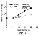
- FIG. 8 shows the result of examination of the relation between the volume content (Vf) of the reinforcements 11 of the metal matrix composite 4 and the time of breakdown.
- Aluminum alloy AC8A (JIS.H5202) for casting was used as the material of the matrix 10 and subjected to heat treatment T6 (JIS.H5202) after casting operation.
- FeCrSi alloy (Cr: 20%, Si: 5%) was used for the reinforcements 11, which were manufactured by the aforementioned the melt extraction method.
- a metal matrix composite as a comparative example is a metallic fiber that is composed of AC8A as its matrix and stainless steel (SUS 304) as its reinforcements.
- both the product of the present invention and the comparative example enjoy the development of an effect on their time of breakdown. While the time of breakdown of the comparative example is about 10 6 cycles when the volume content is not lower than 20%, however, the time of breakdown of the metal matrix composite 4 of the present invention, which uses the reinforcements 11 of FeCr(Al, Si) alloy, is 10 7 or more, displaying a considerable improvement. If the content of the reinforcements 11 exceeds 40%, cavities (voids) are created while the matrix 10 is being cast. Therefore, 40% is the upper limit of the content of the reinforcements 11.
- FIGS. 9 to 11 show processes for manufacturing the piston 1 using the ring-shaped preform 11a' shown in FIG. 6B.
- a molten Al alloy to form the matrix 10 is poured into the casting mold 61'.
- the molten A1 alloy poured into the casting mold 61' hardens and forms a piston body portion 1b.
- the molten Al alloy penetrates into spaces between the reinforcements 11 of the preform 11a' and hardens, whereupon the metal matrix composite 4 is formed.
- the semi-finished piston 1' that includes the metal matrix composite 4, as shown in FIG. 10, is manufactured.
- the semi-finished piston 1' is formed with the combustion chamber 2 that has the lip portion 3 with the desired shape as its workable portion including the metal matrix composite 4 is machined in the machining process, as shown in FIG. 11. Further, the top face 1a of the piston 1 and a piston periphery 1c are finished, and the piston pin socket hole 7 is machined.
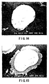
- the inventors hereof conducted various tests for intermetallic compounds that are formed on the interfaces between the matrix 10 and the reinforcements 11.
- the matrix of the metal matrix composite used in the tests is AC8A
- the reinforcements are metallic fibers (diameter: about ⁇ 30 ⁇ m, volume content Vf: 20%) that are formed of FeCrSi alloy (Cr: 20%, Si: 5%) manufactured by the melt extraction method.
- FIG. 14 is a 1,500-magnification photomicrograph of a cross section of the metal matrix composite before heat treatment.
- a substantially circular cross section appearing in the center of FIG. 14 indicates a reinforcement.
- Very minute intermetallic compounds are observed around this reinforcement. The presence of these minute intermetallic compounds implies that a reaction is already caused on the interface between the matrix and the reinforcement when the matrix and the reinforcement are compounded (in the casting process of the matrix). Since the quantity of the intermetallic compounds is very small, however, they never have any bad influences upon the properties of the composite.
- FIG. 15 is a photomicrograph (power: 1,500 magnifications) obtained after the composite was performed solution-treatment at 510°C.
- the whole circumference of a reinforcement is covered with a large quantity of intermetallic compounds.
- These intermetallic compounds are supposed to be grown versions of the minute intermetallic compounds shown in FIG. 14 as nuclei.
- creation of cavities (voids) in the matrix was recognized.
- the cavities are supposed to have been created because the growth of the intermetallic compounds, which are denser than the matrix, caused a substantial change of density in the matrix.
- the abundant intermetallic compounds that cover the whole circumference of the reinforcement are so fragile that they are expected to exert a bad influence upon the fatigue strength of the composite. Further, the creation of the cavities may possibly adversely affect the composite. No growth of the intermetallic compounds was observed in the age hardening (at 170°C for 10 hours).
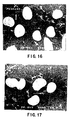
- FIG. 16 is a photomicrograph (500 magnifications) obtained when the composite was performed solution-treatment at 490°C.
- the solution-treatment temperature was at 490°C, as shown in FIG. 16, neither intermetallic compounds nor cavities were observed at all around the reinforcement.
- FIG. 17 is a photomicrograph (500 magnifications) obtained when the composite was performed solution-treatment at 500°C.
- the solution-treatment temperature was at 500°C or thereabout, as shown in FIG. 17, a slight growth of the intermetallic compounds was recognized. However, these intermetallic compounds are not all, and creation of cavities was not recognized.
- FIG. 18 is a photomicrograph (500 magnifications) obtained when the composite was performed solution-treatment at 510°C. When the solution-treatment temperature was at 510°C, as shown in FIG. 18, growth of the intermetallic compounds covering the whole circumference of the reinforcement was recognized.
- the inventors hereof examined the way the hardness of the composite changes depending on the solution-treatment temperature. The result is shown in FIG. 12.
- the axis of ordinate of FIG. 12 represents Rockwell B hardness (test load: 100 kg).
- test load 100 kg.
- the solution-treatment temperature was at 470°C or above, as shown in FIG. 12, higher hardness than that of an AC8A material that contains no reinforcements was obtained.
- the hardness drastically increased at 510°C or thereabout, since a plenty of intermetallic compounds were produced.
- the intermetallic compounds constitute a factor that exerts a bad influence upon the fatigue strength of the metal matrix composite.
- the metal matrix composite can obtain its maximum hardness at temperatures of about 490°C to 500°C except for the temperature (510°C) at which the intermetallic compounds grow.
- the solution-treatment temperature preferably ranges from 470°C to 500°C, and especially, from 490°C to 500°C.
- the rotary bending fatigue test (JIS.Z2274) was conducted at the ambient temperature of 300°C and under repeated stress of 60 MPa.
- the matrix of the composite used in the test is AC8A
- the reinforcements are metallic fibers (diameter: about ⁇ 30 ⁇ m, volume content Vf: 20%) that are formed of FeCrSi alloy (Cr: 20%, Si: 5%).
- the composite was performed solution-treatment at 490°C enjoyed about 10 times as high durability as that of the AC8A material that contains no reinforcements.
Landscapes
- Engineering & Computer Science (AREA)
- Chemical & Material Sciences (AREA)
- Mechanical Engineering (AREA)
- Materials Engineering (AREA)
- Metallurgy (AREA)
- Organic Chemistry (AREA)
- Combustion & Propulsion (AREA)
- General Engineering & Computer Science (AREA)
- Nanotechnology (AREA)
- Manufacture Of Alloys Or Alloy Compounds (AREA)
Claims (7)
- Ein Kolben aus einer Metallmatrixzusammensetzung (4) aus einer Aluminiumlegierungsmatrix (10) und Verstärkungen (11), die in die Matrix (10) hineingemischt sind, wobei der Volumenanteil der Verstärkungen im Bereich von 10 bis 50 % liegt und besagte Verstärkungen (11) metallische Fasern umfassen, die Eisen und Chrom umfassen und zusätzlich Aluminium und/oder Silizium umfassen, wobei der Chromanteil und der Aluminium- und/oder Siliziumanteil der besagten Verstärkungen (11) jeweils im Bereich von 5 bis 30 % und von 3 bis 10 % liegt.
- Ein Verfahren zum Herstellen eines Kolbens nach Anspruch 1.
- Ein Verfahren nach Anspruch 2, das dadurch gekennzeichnet ist, dass eine Lösungsbehandlung bei Temperaturen durchgeführt wird, dass Reaktanten auf den Begrenzungsflächen zwischen der Matrix (10) und den Verstärkungen (11) unterdrückt sind.
- Verfahren nach wenigstens der Ansprüche 2 bis 3, dadurch gekennzeichnet, dass die Reaktanten intermetallische Komponenten sind, wobei die Lösungsbehandlung in einem Temperaturbereich von 470 °C bis 500 °C durchgeführt wird.
- Verfahren nach wenigstens einem der Ansprüche 2 bis 4, dadurch gekennzeichnet, dass die Verstärkungen (11) durch Sinterprozesse in eine vorbestimmte Form vorgeformt werden.
- Verfahren nach einem der Ansprüche 2 bis 5, dadurch gekennzeichnet, dass die Verstärkungen (11) metallische Fasern mit einem Faserdurchmesser von 20 µm bis 100 µm sind, die durch Schmelzextraktionsverfahren hergestellt sind und eine unregelmäßige äußere Oberfläche aufweisen.
- Verfahren gemäß einem der Ansprüche 2 bis 6, dadurch gekennzeichnet, dass der Volumenanteil der Verstärkungen (11) im Bereich von 10 % bis 40 % liegt.
Applications Claiming Priority (5)
| Application Number | Priority Date | Filing Date | Title |
|---|---|---|---|
| JP22635999 | 1999-08-10 | ||
| JP22635999 | 1999-08-10 | ||
| JP2000069001 | 2000-03-13 | ||
| JP2000069001 | 2000-03-13 | ||
| PCT/JP2000/005373 WO2001012871A1 (fr) | 1999-08-10 | 2000-08-10 | Materiau composite a matrice metallique et son utilisation dans un piston |
Publications (3)
| Publication Number | Publication Date |
|---|---|
| EP1132490A1 EP1132490A1 (de) | 2001-09-12 |
| EP1132490A4 EP1132490A4 (de) | 2005-04-13 |
| EP1132490B1 true EP1132490B1 (de) | 2007-01-03 |
Family
ID=26527137
Family Applications (1)
| Application Number | Title | Priority Date | Filing Date |
|---|---|---|---|
| EP20000951939 Expired - Lifetime EP1132490B1 (de) | 1999-08-10 | 2000-08-10 | Kolben mit einem metallischen verbundwerkstoff |
Country Status (5)
| Country | Link |
|---|---|
| US (1) | US6432557B2 (de) |
| EP (1) | EP1132490B1 (de) |
| JP (1) | JP3681354B2 (de) |
| DE (1) | DE60032728T2 (de) |
| WO (1) | WO2001012871A1 (de) |
Cited By (2)
| Publication number | Priority date | Publication date | Assignee | Title |
|---|---|---|---|---|
| RU2555737C1 (ru) * | 2014-01-09 | 2015-07-10 | Федеральное государственное бюджетное образовательное учреждение высшего профессионального образования "Волгоградский государственный технический университет" (ВолгГТУ) | Литейный сплав на основе алюминия для получения пропиткой композиционных материалов с углеграфитовым каркасом |
| RU2653958C1 (ru) * | 2017-04-21 | 2018-05-15 | Федеральное государственное бюджетное образовательное учреждение высшего образования "Волгоградский государственный технический университет" (ВолгГТУ) | Сплав на основе алюминия для получения композиционных материалов |
Families Citing this family (8)
| Publication number | Priority date | Publication date | Assignee | Title |
|---|---|---|---|---|
| EP1808621A1 (de) * | 2004-11-01 | 2007-07-18 | Kabushiki Kaisha Toyota Jidoshokki | Druckbehälter, kompressor und giessverfahren für zylinderblock |
| DE102004056519B4 (de) * | 2004-11-24 | 2017-07-13 | Mahle Gmbh | Verfahren zur Herstellung eines Kolbens für einen Verbrennungsmotor |
| DE102005029103B3 (de) * | 2005-06-23 | 2007-01-04 | Federal-Mogul Nürnberg GmbH | Kolben für einen Verbrennungsmotor und Verfahren zur Herstellung des Kolbens |
| DE102006007148A1 (de) | 2006-02-16 | 2007-08-30 | Volkswagen Ag | Kolben für Verbrennungsmotoren und Verfahren zur Herstellung eines Kolbens für Verbrennungsmotoren |
| DE102010042402A1 (de) * | 2010-10-13 | 2012-04-19 | Federal-Mogul Burscheid Gmbh | Verfahren zur Herstellung eines Kolbenrings mit eingelagerten Partikeln |
| DE102011083860A1 (de) * | 2011-09-30 | 2013-04-04 | Aktiebolaget Skf | Keramikelement und Verfahren zur Herstellung eines Keramikelements |
| JP6638406B2 (ja) * | 2016-01-12 | 2020-01-29 | いすゞ自動車株式会社 | 内燃機関用ピストンおよび内燃機関用ピストンの製造方法 |
| CN107267847B (zh) * | 2017-06-14 | 2019-08-27 | 湘潭大学 | 一种抗高温氧化、耐碱蚀的铁基多孔材料及其制备方法 |
Family Cites Families (14)
| Publication number | Priority date | Publication date | Assignee | Title |
|---|---|---|---|---|
| JPS5967335A (ja) * | 1982-09-27 | 1984-04-17 | Honda Motor Co Ltd | 繊維強化複合部材の製造方法 |
| DE3418405A1 (de) * | 1983-05-18 | 1984-11-29 | Mazda Motor Corp., Hiroshima | Verfahren zur herstellung von gussteilen aus aluminiumlegierung und aus einer aluminiumlegierung bestehender kolben |
| JPS59220273A (ja) | 1983-05-31 | 1984-12-11 | Nissan Motor Co Ltd | 繊維複合鋳造部材の製造方法 |
| JPS6128006A (ja) | 1984-07-16 | 1986-02-07 | 丸五産業株式会社 | 塩化ビニ−ル製作業用手袋の製造方法 |
| JPS61231130A (ja) | 1985-04-05 | 1986-10-15 | Mazda Motor Corp | 複合材成形に供する繊維成形体の製造方法 |
| JPS6233730A (ja) * | 1985-08-02 | 1987-02-13 | Nissan Motor Co Ltd | 耐摩耗性複合材料 |
| BR8700527A (pt) * | 1987-01-29 | 1988-08-16 | Metal Leve Sa | Processo de fabricacao de embolo e embolo para motores de combustao interna |
| US4962003A (en) * | 1988-04-27 | 1990-10-09 | Lhymn Yoon O | Development of fusible alloy composites |
| US5001961A (en) * | 1988-05-09 | 1991-03-26 | Airfoil Textron Inc. | Braided preform |
| JPH0830250B2 (ja) * | 1989-12-13 | 1996-03-27 | 日本冶金工業株式会社 | 製造性に優れるステンレス鋼ファイバー |
| US5523171A (en) * | 1993-12-20 | 1996-06-04 | Hyundai Motor Company | Reinforced material for an automobile connecting rod |
| JPH0830250A (ja) | 1994-07-20 | 1996-02-02 | Fujitsu Ltd | 文章処理装置 |
| JP3242573B2 (ja) * | 1996-08-07 | 2001-12-25 | トヨタ自動車株式会社 | 高温耐酸化性及び耐熱変形性に優れたステンレス鋼線及び繊維 |
| DE19712624C2 (de) * | 1997-03-26 | 1999-11-04 | Vaw Motor Gmbh | Aluminiummatrix-Verbundwerkstoff und Verfahren zu seiner Herstellung |
-
2000
- 2000-08-10 JP JP2001516956A patent/JP3681354B2/ja not_active Expired - Fee Related
- 2000-08-10 DE DE2000632728 patent/DE60032728T2/de not_active Expired - Lifetime
- 2000-08-10 WO PCT/JP2000/005373 patent/WO2001012871A1/ja active IP Right Grant
- 2000-08-10 EP EP20000951939 patent/EP1132490B1/de not_active Expired - Lifetime
-
2001
- 2001-04-05 US US09/827,606 patent/US6432557B2/en not_active Expired - Fee Related
Cited By (2)
| Publication number | Priority date | Publication date | Assignee | Title |
|---|---|---|---|---|
| RU2555737C1 (ru) * | 2014-01-09 | 2015-07-10 | Федеральное государственное бюджетное образовательное учреждение высшего профессионального образования "Волгоградский государственный технический университет" (ВолгГТУ) | Литейный сплав на основе алюминия для получения пропиткой композиционных материалов с углеграфитовым каркасом |
| RU2653958C1 (ru) * | 2017-04-21 | 2018-05-15 | Федеральное государственное бюджетное образовательное учреждение высшего образования "Волгоградский государственный технический университет" (ВолгГТУ) | Сплав на основе алюминия для получения композиционных материалов |
Also Published As
| Publication number | Publication date |
|---|---|
| EP1132490A1 (de) | 2001-09-12 |
| EP1132490A4 (de) | 2005-04-13 |
| US6432557B2 (en) | 2002-08-13 |
| WO2001012871A1 (fr) | 2001-02-22 |
| JP3681354B2 (ja) | 2005-08-10 |
| DE60032728T2 (de) | 2007-04-26 |
| DE60032728D1 (de) | 2007-02-15 |
| US20010028948A1 (en) | 2001-10-11 |
Similar Documents
| Publication | Publication Date | Title |
|---|---|---|
| EP0211557B1 (de) | Verbindung metallischer und keramischer Gegenstände | |
| US4734968A (en) | Method for making a valve-seat insert for internal combustion engines | |
| EP0665777B1 (de) | Sinterwerkstücke | |
| EP1132490B1 (de) | Kolben mit einem metallischen verbundwerkstoff | |
| JPH0891951A (ja) | アルミニウムと窒化ケイ素の接合体およびその製造方法 | |
| JPH02107868A (ja) | ピストン中の構成部品結合方法 | |
| CN108796335A (zh) | 复合结构硬质合金制品的制备方法 | |
| JPWO2004087351A1 (ja) | ダイカストマシン用断熱プランジャースリーブ | |
| Hamada et al. | Experimental investigation of mechanical and tribological characteristics of Al 2024 matrix composite reinforced by yttrium oxide particles | |
| JP4133078B2 (ja) | 繊維強化金属の製造方法 | |
| US4656100A (en) | Fiber reinforced material with matrix metal containing copper and reinforcing fibers containing alumina | |
| JP2004188452A (ja) | 複合部材及びその製造方法 | |
| JPS6021306A (ja) | 複合強化部材の製造方法 | |
| US6821313B2 (en) | Reduced temperature and pressure powder metallurgy process for consolidating rhenium alloys | |
| JP4178070B2 (ja) | 焼結用予成形体のキャニング方法およびそれによる焼結材料の製造方法 | |
| JP4524591B2 (ja) | 複合材料およびその製造方法 | |
| RU2230628C1 (ru) | Способ получения изделия из металлического композиционного материала | |
| US7270782B2 (en) | Reduced temperature and pressure powder metallurgy process for consolidating rhenium alloys | |
| JP2001073869A (ja) | 上下面に溝を有する焼結体でリング溝を強化した内燃機関用アルミニウム合金製ピストン及びその製造方法 | |
| EP0240308B1 (de) | Brennkraftmaschinenkolben und Verfahren zu dessen Verstärkung | |
| JP2008200703A (ja) | 金属基複合材の製造方法 | |
| JP2679160B2 (ja) | 金属基複合材料部材の製造方法 | |
| JPH10130701A (ja) | 金属間化合物複合材料及びその製造方法 | |
| JPH0797644A (ja) | 金属基複合体およびその製造方法 | |
| JPH03189063A (ja) | 鉄系多孔質強化材およびそれと非鉄金属との複合体 |
Legal Events
| Date | Code | Title | Description |
|---|---|---|---|
| PUAI | Public reference made under article 153(3) epc to a published international application that has entered the european phase |
Free format text: ORIGINAL CODE: 0009012 |
|
| 17P | Request for examination filed |
Effective date: 20010502 |
|
| AK | Designated contracting states |
Kind code of ref document: A1 Designated state(s): AT BE CH CY DE DK ES FI FR GB GR IE LI LU MC NL PT SE |
|
| RBV | Designated contracting states (corrected) |
Designated state(s): DE FR GB |
|
| A4 | Supplementary search report drawn up and despatched |
Effective date: 20050301 |
|
| 17Q | First examination report despatched |
Effective date: 20050602 |
|
| GRAP | Despatch of communication of intention to grant a patent |
Free format text: ORIGINAL CODE: EPIDOSNIGR1 |
|
| RTI1 | Title (correction) |
Free format text: PISTON WITH A METAL MATRIX COMPOSITE |
|
| GRAS | Grant fee paid |
Free format text: ORIGINAL CODE: EPIDOSNIGR3 |
|
| GRAA | (expected) grant |
Free format text: ORIGINAL CODE: 0009210 |
|
| AK | Designated contracting states |
Kind code of ref document: B1 Designated state(s): DE FR GB |
|
| REG | Reference to a national code |
Ref country code: GB Ref legal event code: FG4D |
|
| REF | Corresponds to: |
Ref document number: 60032728 Country of ref document: DE Date of ref document: 20070215 Kind code of ref document: P |
|
| ET | Fr: translation filed | ||
| PLBE | No opposition filed within time limit |
Free format text: ORIGINAL CODE: 0009261 |
|
| STAA | Information on the status of an ep patent application or granted ep patent |
Free format text: STATUS: NO OPPOSITION FILED WITHIN TIME LIMIT |
|
| 26N | No opposition filed |
Effective date: 20071005 |
|
| PGFP | Annual fee paid to national office [announced via postgrant information from national office to epo] |
Ref country code: FR Payment date: 20100824 Year of fee payment: 11 Ref country code: DE Payment date: 20100812 Year of fee payment: 11 |
|
| PGFP | Annual fee paid to national office [announced via postgrant information from national office to epo] |
Ref country code: GB Payment date: 20100811 Year of fee payment: 11 |
|
| GBPC | Gb: european patent ceased through non-payment of renewal fee |
Effective date: 20110810 |
|
| REG | Reference to a national code |
Ref country code: FR Ref legal event code: ST Effective date: 20120430 |
|
| REG | Reference to a national code |
Ref country code: DE Ref legal event code: R119 Ref document number: 60032728 Country of ref document: DE Effective date: 20120301 |
|
| PG25 | Lapsed in a contracting state [announced via postgrant information from national office to epo] |
Ref country code: FR Free format text: LAPSE BECAUSE OF NON-PAYMENT OF DUE FEES Effective date: 20110831 Ref country code: GB Free format text: LAPSE BECAUSE OF NON-PAYMENT OF DUE FEES Effective date: 20110810 |
|
| PG25 | Lapsed in a contracting state [announced via postgrant information from national office to epo] |
Ref country code: DE Free format text: LAPSE BECAUSE OF NON-PAYMENT OF DUE FEES Effective date: 20120301 |