EP1132230A1 - Dispositif de chauffage et/ou climatisation de l'habitacle d'un véhicule à moteur - Google Patents
Dispositif de chauffage et/ou climatisation de l'habitacle d'un véhicule à moteur Download PDFInfo
- Publication number
- EP1132230A1 EP1132230A1 EP01105682A EP01105682A EP1132230A1 EP 1132230 A1 EP1132230 A1 EP 1132230A1 EP 01105682 A EP01105682 A EP 01105682A EP 01105682 A EP01105682 A EP 01105682A EP 1132230 A1 EP1132230 A1 EP 1132230A1
- Authority
- EP
- European Patent Office
- Prior art keywords
- loop
- heat
- evaporator
- heat pump
- condenser
- Prior art date
- Legal status (The legal status is an assumption and is not a legal conclusion. Google has not performed a legal analysis and makes no representation as to the accuracy of the status listed.)
- Granted
Links
Images

Classifications
-
- B—PERFORMING OPERATIONS; TRANSPORTING
- B60—VEHICLES IN GENERAL
- B60H—ARRANGEMENTS OF HEATING, COOLING, VENTILATING OR OTHER AIR-TREATING DEVICES SPECIALLY ADAPTED FOR PASSENGER OR GOODS SPACES OF VEHICLES
- B60H1/00—Heating, cooling or ventilating devices
- B60H1/02—Heating, cooling or ventilating devices the heat being derived from the propulsion plant
- B60H1/14—Heating, cooling or ventilating devices the heat being derived from the propulsion plant other than from cooling liquid of the plant
- B60H1/18—Heating, cooling or ventilating devices the heat being derived from the propulsion plant other than from cooling liquid of the plant the air being heated from the plant exhaust gases
- B60H1/20—Heating, cooling or ventilating devices the heat being derived from the propulsion plant other than from cooling liquid of the plant the air being heated from the plant exhaust gases using an intermediate heat-transferring medium
-
- B—PERFORMING OPERATIONS; TRANSPORTING
- B60—VEHICLES IN GENERAL
- B60H—ARRANGEMENTS OF HEATING, COOLING, VENTILATING OR OTHER AIR-TREATING DEVICES SPECIALLY ADAPTED FOR PASSENGER OR GOODS SPACES OF VEHICLES
- B60H1/00—Heating, cooling or ventilating devices
- B60H1/00007—Combined heating, ventilating, or cooling devices
-
- B—PERFORMING OPERATIONS; TRANSPORTING
- B60—VEHICLES IN GENERAL
- B60H—ARRANGEMENTS OF HEATING, COOLING, VENTILATING OR OTHER AIR-TREATING DEVICES SPECIALLY ADAPTED FOR PASSENGER OR GOODS SPACES OF VEHICLES
- B60H1/00—Heating, cooling or ventilating devices
- B60H1/00642—Control systems or circuits; Control members or indication devices for heating, cooling or ventilating devices
- B60H1/00814—Control systems or circuits characterised by their output, for controlling particular components of the heating, cooling or ventilating installation
- B60H1/00878—Control systems or circuits characterised by their output, for controlling particular components of the heating, cooling or ventilating installation the components being temperature regulating devices
- B60H1/00899—Controlling the flow of liquid in a heat pump system
- B60H1/00914—Controlling the flow of liquid in a heat pump system where the flow direction of the refrigerant does not change and there is a bypass of the condenser
-
- B—PERFORMING OPERATIONS; TRANSPORTING
- B60—VEHICLES IN GENERAL
- B60H—ARRANGEMENTS OF HEATING, COOLING, VENTILATING OR OTHER AIR-TREATING DEVICES SPECIALLY ADAPTED FOR PASSENGER OR GOODS SPACES OF VEHICLES
- B60H1/00—Heating, cooling or ventilating devices
- B60H1/00642—Control systems or circuits; Control members or indication devices for heating, cooling or ventilating devices
- B60H1/00814—Control systems or circuits characterised by their output, for controlling particular components of the heating, cooling or ventilating installation
- B60H1/00878—Control systems or circuits characterised by their output, for controlling particular components of the heating, cooling or ventilating installation the components being temperature regulating devices
- B60H1/00899—Controlling the flow of liquid in a heat pump system
- B60H1/00921—Controlling the flow of liquid in a heat pump system where the flow direction of the refrigerant does not change and there is an extra subcondenser, e.g. in an air duct
-
- B—PERFORMING OPERATIONS; TRANSPORTING
- B60—VEHICLES IN GENERAL
- B60H—ARRANGEMENTS OF HEATING, COOLING, VENTILATING OR OTHER AIR-TREATING DEVICES SPECIALLY ADAPTED FOR PASSENGER OR GOODS SPACES OF VEHICLES
- B60H1/00—Heating, cooling or ventilating devices
- B60H1/02—Heating, cooling or ventilating devices the heat being derived from the propulsion plant
- B60H1/025—Heating, cooling or ventilating devices the heat being derived from the propulsion plant from both the cooling liquid and the exhaust gases of the propulsion plant
-
- B—PERFORMING OPERATIONS; TRANSPORTING
- B60—VEHICLES IN GENERAL
- B60H—ARRANGEMENTS OF HEATING, COOLING, VENTILATING OR OTHER AIR-TREATING DEVICES SPECIALLY ADAPTED FOR PASSENGER OR GOODS SPACES OF VEHICLES
- B60H1/00—Heating, cooling or ventilating devices
- B60H1/32—Cooling devices
- B60H1/3204—Cooling devices using compression
-
- B—PERFORMING OPERATIONS; TRANSPORTING
- B60—VEHICLES IN GENERAL
- B60H—ARRANGEMENTS OF HEATING, COOLING, VENTILATING OR OTHER AIR-TREATING DEVICES SPECIALLY ADAPTED FOR PASSENGER OR GOODS SPACES OF VEHICLES
- B60H1/00—Heating, cooling or ventilating devices
- B60H1/32—Cooling devices
- B60H1/3204—Cooling devices using compression
- B60H1/3228—Cooling devices using compression characterised by refrigerant circuit configurations
- B60H1/32284—Cooling devices using compression characterised by refrigerant circuit configurations comprising two or more secondary circuits, e.g. at evaporator and condenser side
-
- B—PERFORMING OPERATIONS; TRANSPORTING
- B60—VEHICLES IN GENERAL
- B60H—ARRANGEMENTS OF HEATING, COOLING, VENTILATING OR OTHER AIR-TREATING DEVICES SPECIALLY ADAPTED FOR PASSENGER OR GOODS SPACES OF VEHICLES
- B60H1/00—Heating, cooling or ventilating devices
- B60H1/00642—Control systems or circuits; Control members or indication devices for heating, cooling or ventilating devices
- B60H1/00814—Control systems or circuits characterised by their output, for controlling particular components of the heating, cooling or ventilating installation
- B60H1/00878—Control systems or circuits characterised by their output, for controlling particular components of the heating, cooling or ventilating installation the components being temperature regulating devices
- B60H2001/00928—Control systems or circuits characterised by their output, for controlling particular components of the heating, cooling or ventilating installation the components being temperature regulating devices comprising a secondary circuit
-
- B—PERFORMING OPERATIONS; TRANSPORTING
- B60—VEHICLES IN GENERAL
- B60H—ARRANGEMENTS OF HEATING, COOLING, VENTILATING OR OTHER AIR-TREATING DEVICES SPECIALLY ADAPTED FOR PASSENGER OR GOODS SPACES OF VEHICLES
- B60H1/00—Heating, cooling or ventilating devices
- B60H1/00642—Control systems or circuits; Control members or indication devices for heating, cooling or ventilating devices
- B60H1/00814—Control systems or circuits characterised by their output, for controlling particular components of the heating, cooling or ventilating installation
- B60H1/00878—Control systems or circuits characterised by their output, for controlling particular components of the heating, cooling or ventilating installation the components being temperature regulating devices
- B60H2001/00949—Control systems or circuits characterised by their output, for controlling particular components of the heating, cooling or ventilating installation the components being temperature regulating devices comprising additional heating/cooling sources, e.g. second evaporator
Definitions
- the invention relates to a heating device and / or air conditioning of the passenger compartment of a motor vehicle comprising a main heating loop and a heating loop auxiliary heating.
- a device having an engine cooling loop in which circulates a heat transfer fluid which takes heat on the engine and which returns it to an air heater, a heat pump loop in which a fluid circulates refrigerant, this loop containing a compressor, a evaporator constituting a cold source of the heat at which the refrigerant draws heat on the external environment, and a condenser constituting a heat source from the heat pump to which the fluid refrigerant gives off heat, the condenser being integrated to the engine cooling loop upstream of the heater.
- the main heating of the passenger compartment is achieved by means of a loop of engine cooling which draws heat from the engine and transfers it to a heat exchanger, called air heater, swept by an air flow which is directed in the passenger compartment.
- a loop of engine cooling which draws heat from the engine and transfers it to a heat exchanger, called air heater, swept by an air flow which is directed in the passenger compartment.
- Japanese document JP 10-76837 (Calsonic) describes a passenger compartment heater of a motor vehicle having a cooling circuit with which it is associated an additional heating circuit which produces a pump heat, by which heat is taken from a cold source by evaporation of a fluid in an evaporator and we transfer this heat to a hot source by condensation of the same fluid in a condenser.
- An exchanger of heat constituting the cold source of the heat pump is integrated in the cooling circuit upstream of the motor, and a heat exchanger constituting the source of the heat pump is integrated into this same circuit in upstream of the heater.
- the refrigerant of the heat pump transfers heat to the heat transfer fluid upstream of the heater.
- the temperature of the heat transfer fluid of the cooling circuit is not increased at the inlet of the motor. On the contrary, it is lowered by the levy from the heat source of the heat pump. Of the so the amount of heat extracted from the engine is not decreased, but increased.
- the energy efficiency of auxiliary heating is significantly improved compared to a device such as that which has been previously described.
- this device has several drawbacks. On the one hand, it does not allow the cooling of the passenger compartment in case of high outside temperature. On the other hand, the heat taken from the cooling circuit, heating the coolant of the heat pump, can lead to an inadmissible suction pressure for the compressor, which can lead to its destruction.
- the object of the invention is in particular to remedy these drawbacks. It offers a heating device and / or air conditioning which cools the passenger compartment in the event of high outside heat. On the other hand, this device allows to control the fluid pressure of the pump loop at heat at the compressor inlet.
- the heating device of the invention has an air conditioning branch containing a condenser and an evaporator, this loop having an upstream end connected to the heat pump loop downstream of the compressor, and a downstream end connected to the pump loop at heat upstream of the compressor, and switching means allowing the coolant to circulate either in the heat pump loop, either in the pump branch heat, so as to form a heat pump loop.
- the device can operate according to at least three different modes.
- a first mode corresponding to a moderate outside temperature
- the cooling loop of the engine works alone.
- a second mode corresponding at a more severe outside temperature or at starting the vehicle.
- the engine cooling loop and the heat pump loop operate simultaneously.
- a third mode corresponding to a temperature high outdoor, only air conditioning loop works.
- the evaporator is integrated in the cooling loop, upstream of the engine.
- the evaporator takes heat on an environment outside the cooling circuit of the motor.
- the loop cooling includes means of control, for example at least one valve, which controls the quantity of heat transfer fluid passing through the evaporator.
- the cooling loop includes means for controls, for example at least one valve, which allow control the amount of heat transfer fluid flowing through the condenser.
- the air conditioning branch includes a refrigerant accumulator.
- the evaporator constitutes advantageously a common coolant accumulator to the air conditioning loop and to the pump loop to heat.
- the heating device has a modular box containing the evaporator, the evaporator control means, the non-return valve, the condenser, the condenser control means, the switching means, and the expansion means of the heat pump loop.
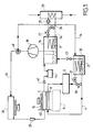
- a motor vehicle has an engine 2.
- the engine 2 is a heat engine, but it could also be an engine of another type, like an electric motor.
- the engine 2 is cooled by a cooling loop 4 which allows the main heating of the passenger compartment 6 shown schematically in dotted lines.
- the cooling loop 4 in which a refrigerant circulates (in example of brine), contains a radiator or air heater 8 crossed by a flow of air blown by a blower 10. This air flow heats up through the air heater which heats the passenger compartment 6.
- the device provides for a second loop, namely a heat pump loop 14 which performs additional heating of the glycol water in the loop cooling 4.
- the heat pump loop 14 comprises successively an evaporator 16, a compressor 18, a condenser 20 and expansion means 22 interposed between the condenser 20 and the evaporator 16.
- the evaporator 16 constitutes a cold source to which the heat pump loop takes heat from the outside environment.
- the evaporator 16 incorporates an exchanger of heat 17 between the refrigerant of the circuit of the loop 14 and a heat transfer fluid which heats up on contact from an external source 23 such as the exhaust pipe or the engine oil circuit.
- This fluid circulates in a loop 24 under the action of a pump 25.
- a valve 26 mounted in bypass on the loop 24, and more particularly on the heat exchanger 17, regulates the amount of fluid flowing through the evaporator 16.
- the valve 26 may in particular be a regulated valve or a thermostatic valve.
- a valve 27 is placed between valve 26 and heat exchanger 17. This valve allows to completely cut the circulation of the fluid in the heat exchanger 17 of the evaporator 16.
- the valve 27 is open when the valve 26 is closed, and vice versa.
- the valves 26 and 27 could be assembled in a three-way valve.
- the compressor 18 can be a displacement compressor variable whose displacement control is done so internal or external.
- the condenser 20 constitutes the hot source of the heat. It incorporates a heat exchanger 21 with water of the engine cooling loop 4.
- the condenser 20 is mounted just upstream of the heater 8.
- the water in the cooling circuit 4 is heated by its passage in condenser 20. It therefore enters the heater at a higher temperature, which allows increase the temperature of the air flow blown into cockpit 6 and therefore provide additional heating if needed.
- valve 30 is mounted in derivation of loop 4 across the condenser 20, therefore of the heat exchanger 21, in order to regulate the amount of heat transfer fluid passing through the condenser.
- the valve 30 can in particular be a regulated valve or a thermostatic valve.
- valve 31 is placed between the valve 30 and the heat exchanger 21. This valve cuts off the circulation of the fluid in the heat exchanger heat 21 of the condenser 20.
- the valve 31 is open when valve 30 is closed, and vice versa.
- the valves 30 and 31 could be combined into a gate valve three ways.
- the level of the suction pressure of the compressor 18 is very important for the functioning of the heat pump. If you add too much heat to the evaporator 16, the suction pressure of the compressor 18 increase, which could lead to pressure level incompatible with the characteristics of compressor resistance.
- the device of the invention allows to regulate the suction pressure of compressor 18 by controlling the fraction of the fluid flowing respectively in evaporator 16 and in the controlled bypass through valve 26. Passing a small amount of fluid in the evaporator, the heat input is reduced and, therefore, the suction pressure of the compressor. Conversely, by passing a large amount of fluid in the evaporator, the heat input is increased and, by Therefore, the suction pressure of the compressor 18.
- the device of the invention therefore provides a simple and effective for regulating the suction pressure of the compressor.
- the flow rate of circulating fluid is reduced in the evaporator 16 by further opening the valve 26 until the compressor suction pressure reaches the level from which it begins to reduce its displacement by itself (internal control) or to from which the displacement can be controlled from the outside (external control).
- the valve 30 improves the priming of the pump to low temperature heat of the loop water temperature cooling 4.
- the flow is reduced water in the high-pressure water-refrigerant exchanger, constituting the condenser 20.
- the heat dissipation being reduced to the hot spring, the temperature of the latter increases and condensing of the refrigerant occurs at a higher pressure, which loads the compressor more 18.
- the motor 2 must then provide a greater effort, which allows more calories to be injected into the circuit water.
- the heating and / or air conditioning device of the invention comprises an air conditioning branch 34.
- This branch contains a condenser 36, expansion means 38, an evaporator 40, a non-return valve 42 and an accumulator refrigerant 44.
- the branch 34 is connected to the heat pump loop 14 in downstream of compressor 18.
- branch 34 is connected to the heat pump loop upstream of the compressor 18 and more particularly at exchanger 16.
- the same refrigerant circulates in the pump circuit to heat and in branch 34.
- Switching means for example a three-way valve 48, allow to make circulate the refrigerant either in loop 14 or in branch 34. Two loops are thus produced, namely a heat pump loop and an air conditioning loop, which have a common part in which we find in especially a common compressor.
- the device can thus operate according to at least three different modes.
- the cooling loop 4 is sufficient to heat the passenger compartment 6.
- the valve 30 is completely open in such a way so that all the glycol water circulates exclusively between motor 2 and heater 8.
- the cooling loop and the heat pump loop 14 are working simultaneously.
- the three-way valve 48 is controlled from so that the refrigerant circulates in the loop heat pump.
- the valves 26 and 30 are completely or partially closed.
- the refrigerant in the heat pump draws heat from the outside environment, for example on the muffler 22. This heat, increased by the mechanical compression energy of the fluid, is transferred to the brine of the cooling circuit at the condenser 20.
- the brine therefore enters in the heater at a higher temperature, which increases the temperature of the air flow blown into the passenger compartment 6 and therefore provide additional heating.
- a third operating mode corresponding to a high outside temperature, there is no need to heat the passenger compartment, but on the contrary cool it.
- the loop air conditioning works.
- the three-way valve 48 is controlled so that the coolant circulates in the air conditioning loop. Valves 26 and 30 are open.
- the air conditioning loop allows to send conventionally in the passenger compartment 6 an air flow set movement by the blower 10, which is common to the branch 34 and to branch 4, and cooled by its passage through the evaporator 40.
- valve 30 can be closed and valve 31 opened.
- the circulation of water in exchanger 21 of condenser 20 has no impact on performance and allows to remove the coolant and push it to the air conditioning loop.
- FIG. 2 An alternative embodiment of the device of FIG. 1.
- This variant is distinguished by the fact that the cold source of the heat pump, namely evaporator 16, draws heat from the loop motor 4 cooling 4.
- loop 4 passes through the evaporator 16 so as to constitute an exchanger low pressure heat between the loop fluid 4 and the refrigerant of the heat pump loop 14.
- a valve 26 is mounted in bypass at the terminals of the evaporator 16, and a similar valve 27 is also provided to that of FIG. 1.
- the water temperature is increased at the outlet of the air heater and therefore at the engine inlet. That leads to a decrease in the amount of heat extracted of the motor.
- valves 26 and 27, as well as that of valves 30 and 31 are identical to what has been described in reference to FIG. 1.
- the valve 26 allows the regulation of the suction pressure of the compressor 18, as well as the regulation of the power of the heat pump.
- Valve 30 facilitates priming of the heat pump at very low temperature.
- the valves 27 and 31 are open when the valves 26 and 30 are closed, and vice versa.
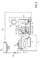
- FIG. 3 a second embodiment of the invention which comprises a modular box 52.
- the interior volume of the housing 52 is separated in two by a internal partition 54 which determines two chambers, namely respectively a chamber 16 which acts as an evaporator and a chamber 20 which acts as a condenser.
- the cooling loop 4 passes through the chamber 16 before returning to the engine.
- loop 4 passes through the condenser chamber 20.
- the valves 26 and 27 are housed inside the chamber 16 and the valves 30 and 31 inside the chamber 20.
- the valve non-return valve 42 is contained in chamber 16 and the valve three lanes 48 in room 20.
- the modular box 52 constitutes a set which contains all the elements necessary for the realization of the circuit of auxiliary heating. To set it up, you just need to plan the necessary connections.
- the other elements of the system heating, in particular the condenser and the evaporator of the air conditioning circuit, as well as the air heater, are classics. They therefore do not require any modification.
Landscapes
- Engineering & Computer Science (AREA)
- Physics & Mathematics (AREA)
- Thermal Sciences (AREA)
- Mechanical Engineering (AREA)
- Chemical & Material Sciences (AREA)
- Combustion & Propulsion (AREA)
- Air-Conditioning For Vehicles (AREA)
Abstract
Description
- la figure 1 est une vue schématique d'un dispositif selon un premier mode de réalisation ;
- la figure 2 est une vue schématique d'un dispositif selon une variante du premier mode de réalisation ; et
- la figure 3 représente un second mode de réalisation de l'invention dans lequel le dispositif est contenu dans un boítier modulaire.
Claims (13)
- Dispositif de chauffage et/ou climatisation de l'habitacle d'un véhicule à moteur, comportant une boucle de refroidissement du moteur (4) dans laquelle circule un fluide caloporteur qui prélève de la chaleur sur le moteur (2) et qui la restitue à un aérotherme (8); une boucle de pompe à chaleur dans laquelle circule un fluide réfrigérant, cette boucle contenant un compresseur (18), un évaporateur (16) constituant une source froide de la pompe à chaleur à laquelle le fluide réfrigérant prélève de la chaleur sur le milieu extérieur, et un condenseur (20) constituant une source chaude de la pompe à chaleur à laquelle le fluide réfrigérant cède de la chaleur, le condenseur (20) étant intégré à la boucle de refroidissement du moteur (2) en amont de l'aérotherme,
caractérisé en qu'il comporte une branche de climatisation contenant un condenseur (36) et un évaporateur (40), cette boucle ayant une extrémité amont raccordée à la boucle de pompe à chaleur (14) en aval du compresseur (18), et une extrémité aval raccordée à la boucle de pompe à chaleur (14) en amont du compresseur (18); et des moyens de commutation (48) permettant de faire circuler le fluide réfrigérant soit dans la boucle de pompe à chaleur (14), soit dans la branche de pompe à chaleur, de manière à former une boucle de pompe à chaleur (14). - Dispositif selon la revendication 1, caractérisé en ce que l'évaporateur (16) de la boucle de pompe à chaleur (14) est intégré dans la boucle de refroidissement, en amont du moteur (2).
- Dispositif selon la revendication 1, caractérisé en ce que l'évaporateur (16) prélève de la chaleur sur un milieu extérieur au circuit de refroidissement du moteur (2).
- Dispositif selon l'une des revendications 1 à 3, caractérisé en ce que la boucle de refroidissement comporte des moyens de contrôle (26, 27) qui permettent de contrôler la quantité de fluide caloporteur qui traverse l'évaporateur (16).
- Dispositif selon la revendication 4, caractérisé en ce que les moyens de contrôle qui permettent de contrôler la quantité de fluide caloporteur qui traverse l'évaporateur (16) sont constitués par au moins une vanne (26, 27).
- Dispositif selon l'une des revendications 1 à 5, caractérisé en ce que la boucle de refroidissement comporte des moyens de contrôle (30, 31) qui permettent de contrôler la quantité de fluide caloporteur qui traverse le condenseur (20).
- Dispositif selon la revendication 6, caractérisé en ce que les moyens de contrôle qui permettent de contrôler la quantité de fluide caloporteur qui traverse le condenseur (20) sont constitués par au moins une vanne (30, 31).
- Dispositif selon l'une des revendications 1 à 7, caractérisé en ce que la branche de climatisation comporte un accumulateur de fluide réfrigérant (44).
- Dispositif selon la revendication 8, caractérisé en ce que l'évaporateur (16) constitue un accumulateur de fluide réfrigérant commun à la boucle de climatisation et à la boucle de pompe à chaleur (14).
- Dispositif selon l'une des revendications 1 à 9, caractérisé en ce que la branche de climatisation comporte un clapet anti-retour (42).
- Dispositif selon l'une des revendications 1 à 10, caractérisé en ce que la boucle de pompe à chaleur (14) comporte des moyens de détente (22) pour détendre le fluide réfrigérant entre le condenseur (20) et l'évaporateur (16).
- Dispositif selon l'une des revendications 1 à 11, caractérisé en ce qu'il comporte un boítier modulaire contenant l'évaporateur (16), des moyens de contrôle de l'évaporateur, le clapet anti-retour, le condenseur (20), les moyens de contrôle du condenseur (20), les moyens de commutation, et les moyens de détente de la boucle de pompe à chaleur (14).
- Dispositif selon l'une des revendications 1 à 12, caractérisé en ce que le moteur (2) est un moteur thermique ou un moteur électrique.
Applications Claiming Priority (2)
| Application Number | Priority Date | Filing Date | Title |
|---|---|---|---|
| FR0003125 | 2000-03-10 | ||
| FR0003125A FR2806038B1 (fr) | 2000-03-10 | 2000-03-10 | Dispositif de chauffage et/ou climatisation de l'habitacle d'un vehicule a moteur |
Publications (2)
| Publication Number | Publication Date |
|---|---|
| EP1132230A1 true EP1132230A1 (fr) | 2001-09-12 |
| EP1132230B1 EP1132230B1 (fr) | 2007-06-27 |
Family
ID=8847972
Family Applications (1)
| Application Number | Title | Priority Date | Filing Date |
|---|---|---|---|
| EP01105682A Expired - Lifetime EP1132230B1 (fr) | 2000-03-10 | 2001-03-07 | Dispositif de chauffage et/ou climatisation de l'habitacle d'un véhicule à moteur |
Country Status (5)
| Country | Link |
|---|---|
| US (1) | US7182129B2 (fr) |
| EP (1) | EP1132230B1 (fr) |
| DE (1) | DE60129062T2 (fr) |
| ES (1) | ES2288890T3 (fr) |
| FR (1) | FR2806038B1 (fr) |
Cited By (4)
| Publication number | Priority date | Publication date | Assignee | Title |
|---|---|---|---|---|
| WO2003064194A1 (fr) * | 2002-01-29 | 2003-08-07 | Audi Ag | Installation de climatisation |
| EP2942256A1 (fr) * | 2014-05-08 | 2015-11-11 | Vossloh Kiepe Ges.m.b.H. | Dispositif de chauffage de l'espace voyageur et/ou de la cabine de conduite de véhicules sur rails |
| EP2942257A1 (fr) * | 2014-05-08 | 2015-11-11 | Vossloh Kiepe Ges.m.b.H. | Dispositif de chauffage de l'espace voyageur et/ou de la cabine de conduite de véhicules sur rails |
| WO2025152582A1 (fr) * | 2024-01-18 | 2025-07-24 | 中车大连机车研究所有限公司 | Climatiseur à pompe à chaleur à dioxyde de carbone à fréquence variable à quasi-deux étapes résistant aux basses températures pour véhicule ferroviaire |
Families Citing this family (37)
| Publication number | Priority date | Publication date | Assignee | Title |
|---|---|---|---|---|
| JP2005518981A (ja) * | 2002-03-04 | 2005-06-30 | ルーク ファールツォイク・ヒドラウリク ゲゼルシャフト ミット ベシュレンクテル ハフツング ウント コンパニー コマンディートゲゼルシャフト | 空調装置 |
| JP3953377B2 (ja) * | 2002-07-16 | 2007-08-08 | トヨタ自動車株式会社 | 空調装置 |
| DE10240712A1 (de) * | 2002-09-04 | 2004-03-18 | Robert Bosch Gmbh | System und Verfahren zur Regulierung des Wärmehaushalts eines Fahrzeugs |
| US7063137B2 (en) * | 2003-07-15 | 2006-06-20 | Delphi Technologies, Inc. | Heat pump with secondary loop air-conditioning system |
| DE102004038790A1 (de) * | 2004-08-09 | 2006-02-23 | Behr Gmbh & Co. Kg | Fahrzeug-Kühlsystem |
| JP4201011B2 (ja) * | 2006-03-27 | 2008-12-24 | トヨタ自動車株式会社 | 蓄熱装置 |
| US8517087B2 (en) * | 2007-02-20 | 2013-08-27 | Bergstrom, Inc. | Combined heating and air conditioning system for vehicles |
| ATE552993T1 (de) * | 2008-04-18 | 2012-04-15 | Valeo Systemes Thermiques | Verbesserte heizungs- und luftkühleinheit für ein automobil |
| DE102008028178A1 (de) * | 2008-05-30 | 2009-12-03 | Konvekta Ag | Klimaanlage zur Konditionierung mehrerer Fluide |
| US20100131152A1 (en) * | 2008-09-05 | 2010-05-27 | Sylvain Castonguay | System, device and method for automatically stopping and starting engines of motor vehicles |
| US8051906B2 (en) * | 2008-11-20 | 2011-11-08 | Delphi Technologies, Inc. | Secondary loop-integral heater core and cooler |
| CN102271943A (zh) * | 2009-01-09 | 2011-12-07 | 卡森尼可关精株式会社 | 车辆用空调装置 |
| KR20120036811A (ko) * | 2009-05-29 | 2012-04-18 | 파커-한니핀 코포레이션 | 펌프형 루프 구동식 증기 압축 냉각 시스템 |
| JP5417123B2 (ja) * | 2009-10-29 | 2014-02-12 | 株式会社日立製作所 | 電動車両の冷却システム |
| DE102011108729A1 (de) * | 2011-07-28 | 2013-01-31 | Volkswagen Aktiengesellschaft | Klimatisierung zum Temperieren von Komponenten sowie eines Innenraums eines Kraftfahrzeugs |
| EP3222449A1 (fr) | 2012-02-28 | 2017-09-27 | Japan Climate Systems Corporation | Climatiseur d'air pour véhicule |
| JP6089357B2 (ja) * | 2012-06-29 | 2017-03-08 | パナソニックIpマネジメント株式会社 | 車両用ヒートポンプ装置 |
| DE102013105747B4 (de) * | 2012-07-18 | 2022-06-09 | Hanon Systems | Vorrichtungen zur Wärmeverteilung in einem Kraftfahrzeug |
| US9618242B2 (en) * | 2013-01-16 | 2017-04-11 | GM Global Technology Operations LLC | Method for controlling a thermal storage heat pump system |
| US9459028B2 (en) * | 2013-01-25 | 2016-10-04 | GM Global Technology Operations LLC | Vehicle heat pump system and method utilizing intermediate gas recompression |
| KR101715723B1 (ko) * | 2013-04-23 | 2017-03-14 | 한온시스템 주식회사 | 차량용 히트 펌프 시스템 |
| KR101416416B1 (ko) * | 2013-06-03 | 2014-07-09 | 현대자동차 주식회사 | 전기 자동차용 난방 시스템 |
| US10183550B2 (en) | 2013-08-26 | 2019-01-22 | Ford Global Technologies, Llc | Method and system for heating a vehicle |
| US10131205B2 (en) * | 2013-08-26 | 2018-11-20 | Ford Global Technologies, Llc | Climate control system |
| JP6249314B2 (ja) * | 2013-09-17 | 2017-12-20 | エルジー・ケム・リミテッド | 熱回収装置 |
| US9630474B2 (en) * | 2013-10-29 | 2017-04-25 | Denso International America, Inc. | Thermostatic controlled heat pump water circuit |
| CN104015586B (zh) * | 2014-06-03 | 2016-01-13 | 镇江市高等专科学校 | 涡流式汽车尾气供暖装置及其控制方法 |
| CN104085270B (zh) * | 2014-06-03 | 2016-08-03 | 镇江市高等专科学校 | 汽车尾气供暖装置及其控制方法 |
| KR102182343B1 (ko) * | 2015-01-12 | 2020-11-25 | 한온시스템 주식회사 | 차량용 히트 펌프 시스템 |
| JP6398764B2 (ja) * | 2015-02-06 | 2018-10-03 | 株式会社デンソー | 車両用熱管理システム |
| KR102170463B1 (ko) * | 2015-03-16 | 2020-10-29 | 한온시스템 주식회사 | 차량용 히트 펌프 시스템 |
| US10018155B2 (en) * | 2016-09-21 | 2018-07-10 | Ford Global Technologies, Llc | System and methods for extracting water from a mechanical air conditioning system for water injection |
| DE102017109309A1 (de) * | 2017-05-02 | 2018-11-08 | Hanon Systems | Klimatisierungssystem eines Kraftfahrzeugs und Verfahren zum Betreiben des Klimatisierungssystems |
| DE102018121390A1 (de) * | 2018-09-03 | 2020-03-05 | Hanon Systems | Thermomanagementanordnung für Fahrzeuge sowie Verfahren zum Betreiben einer Thermomanagementanordnung |
| CN110614912B (zh) * | 2019-09-22 | 2022-05-03 | 安徽安凯汽车股份有限公司 | 一种智能温控节油系统 |
| CN111497556B (zh) * | 2020-04-27 | 2022-07-01 | 吉林大学 | 一种带电机余热回收的二氧化碳热泵空调整车热管理系统 |
| US12023983B2 (en) * | 2021-03-24 | 2024-07-02 | Ford Global Technologies, Llc | Methods and systems for instant cabin heat for a vehicle |
Citations (5)
| Publication number | Priority date | Publication date | Assignee | Title |
|---|---|---|---|---|
| JPS6476837A (en) | 1987-09-18 | 1989-03-22 | Olympus Optical Co | Cooling apparatus of ultrasonic endoscope |
| FR2621867A1 (fr) * | 1987-10-16 | 1989-04-21 | Valeo | Installation de chauffage et de climatisation pour vehicule automobile comportant un generateur de chaleur |
| DE19813674C1 (de) * | 1998-03-27 | 1999-04-15 | Daimler Chrysler Ag | Vorrichtung und Verfahren zum Heizen und Kühlen eines Nutzraumes eines Kraftfahrzeuges |
| DE19806654A1 (de) * | 1998-02-18 | 1999-08-19 | Obrist Engineering Gmbh | Klimaanlage für Fahrzeuge |
| US5971290A (en) * | 1997-04-30 | 1999-10-26 | Honda Giken Kogyo Kabushiki Kaisha | Heat exchange system for electric vehicle |
Family Cites Families (16)
| Publication number | Priority date | Publication date | Assignee | Title |
|---|---|---|---|---|
| US3910345A (en) * | 1974-04-22 | 1975-10-07 | James J Whalen | Heating and cooling system |
| FR2288278A1 (fr) * | 1974-10-18 | 1976-05-14 | Bergeon Et Cie | Systeme a pompe de chaleur pour conditionnement de l'interieur de batiments |
| JPS5924134A (ja) * | 1982-07-31 | 1984-02-07 | Aisin Seiki Co Ltd | 空調器用カロリ−メ−タ− |
| US4616484A (en) * | 1984-11-30 | 1986-10-14 | Kysor Industrial Corporation | Vehicle refrigerant heating and cooling system |
| JPS6213944A (ja) * | 1985-07-09 | 1987-01-22 | Kubota Ltd | ヒ−トポンプ |
| JPS63207709A (ja) * | 1987-02-23 | 1988-08-29 | Toyota Motor Corp | 車両用空調装置 |
| JPH02185821A (ja) * | 1989-01-12 | 1990-07-20 | Diesel Kiki Co Ltd | 自動車用空調装置 |
| JP3237187B2 (ja) * | 1991-06-24 | 2001-12-10 | 株式会社デンソー | 空調装置 |
| JPH06143974A (ja) * | 1992-11-12 | 1994-05-24 | Zexel Corp | 空気調和装置 |
| JPH06262936A (ja) * | 1993-03-10 | 1994-09-20 | Calsonic Corp | 自動車用空気調和装置 |
| JPH06262935A (ja) * | 1993-03-10 | 1994-09-20 | Calsonic Corp | 自動車用空気調和装置 |
| JPH06262934A (ja) * | 1993-03-10 | 1994-09-20 | Calsonic Corp | 自動車用空気調和装置 |
| US5641016A (en) * | 1993-12-27 | 1997-06-24 | Nippondenso Co., Ltd. | Air-conditioning apparatus for vehicle use |
| JPH0886517A (ja) * | 1994-09-14 | 1996-04-02 | Ebara Corp | 熱供給設備 |
| JPH1076837A (ja) * | 1996-09-06 | 1998-03-24 | Calsonic Corp | 自動車用暖房装置 |
| JP3952545B2 (ja) * | 1997-07-24 | 2007-08-01 | 株式会社デンソー | 車両用空調装置 |
-
2000
- 2000-03-10 FR FR0003125A patent/FR2806038B1/fr not_active Expired - Lifetime
-
2001
- 2001-03-07 ES ES01105682T patent/ES2288890T3/es not_active Expired - Lifetime
- 2001-03-07 EP EP01105682A patent/EP1132230B1/fr not_active Expired - Lifetime
- 2001-03-07 DE DE60129062T patent/DE60129062T2/de not_active Expired - Lifetime
- 2001-03-12 US US09/802,982 patent/US7182129B2/en not_active Expired - Lifetime
Patent Citations (5)
| Publication number | Priority date | Publication date | Assignee | Title |
|---|---|---|---|---|
| JPS6476837A (en) | 1987-09-18 | 1989-03-22 | Olympus Optical Co | Cooling apparatus of ultrasonic endoscope |
| FR2621867A1 (fr) * | 1987-10-16 | 1989-04-21 | Valeo | Installation de chauffage et de climatisation pour vehicule automobile comportant un generateur de chaleur |
| US5971290A (en) * | 1997-04-30 | 1999-10-26 | Honda Giken Kogyo Kabushiki Kaisha | Heat exchange system for electric vehicle |
| DE19806654A1 (de) * | 1998-02-18 | 1999-08-19 | Obrist Engineering Gmbh | Klimaanlage für Fahrzeuge |
| DE19813674C1 (de) * | 1998-03-27 | 1999-04-15 | Daimler Chrysler Ag | Vorrichtung und Verfahren zum Heizen und Kühlen eines Nutzraumes eines Kraftfahrzeuges |
Cited By (4)
| Publication number | Priority date | Publication date | Assignee | Title |
|---|---|---|---|---|
| WO2003064194A1 (fr) * | 2002-01-29 | 2003-08-07 | Audi Ag | Installation de climatisation |
| EP2942256A1 (fr) * | 2014-05-08 | 2015-11-11 | Vossloh Kiepe Ges.m.b.H. | Dispositif de chauffage de l'espace voyageur et/ou de la cabine de conduite de véhicules sur rails |
| EP2942257A1 (fr) * | 2014-05-08 | 2015-11-11 | Vossloh Kiepe Ges.m.b.H. | Dispositif de chauffage de l'espace voyageur et/ou de la cabine de conduite de véhicules sur rails |
| WO2025152582A1 (fr) * | 2024-01-18 | 2025-07-24 | 中车大连机车研究所有限公司 | Climatiseur à pompe à chaleur à dioxyde de carbone à fréquence variable à quasi-deux étapes résistant aux basses températures pour véhicule ferroviaire |
Also Published As
| Publication number | Publication date |
|---|---|
| US20010020529A1 (en) | 2001-09-13 |
| DE60129062D1 (de) | 2007-08-09 |
| DE60129062T2 (de) | 2008-03-13 |
| FR2806038B1 (fr) | 2002-09-06 |
| US7182129B2 (en) | 2007-02-27 |
| FR2806038A1 (fr) | 2001-09-14 |
| EP1132230B1 (fr) | 2007-06-27 |
| ES2288890T3 (es) | 2008-02-01 |
Similar Documents
| Publication | Publication Date | Title |
|---|---|---|
| EP1132230B1 (fr) | Dispositif de chauffage et/ou climatisation de l'habitacle d'un véhicule à moteur | |
| FR2898544A1 (fr) | Installation de climatisation | |
| EP1282533B1 (fr) | Dispositif optimise de regulation thermique a pompe a chaleur pour vehicule automobile | |
| EP2643643B2 (fr) | Dispositif de conditionnement thermique d'un habitacle de véhicule | |
| FR2804909A1 (fr) | Equipement de climatisation de vehicule, avec un mode de fonctionnement en pompe a chaleur et/ou en rechauffage | |
| FR2834778A1 (fr) | Dispositif de gestion thermique, notamment pour vehicule automobile equipe d'une pile a combustible | |
| FR2780490A1 (fr) | Systeme de reglage de la temperature dans l'habitacle d'un vehicule a moteur electrique | |
| WO2001087655A9 (fr) | Procede et dispositif de regulation thermique d'un habitacle de vehicule automobile | |
| EP3781882B1 (fr) | Dispositif de conditionnement thermique pour véhicule automobile | |
| WO2023025902A1 (fr) | Système de conditionnement thermique pour véhicule automobile | |
| WO2013004935A2 (fr) | Circuit de refroidissement pour vehicule hybride ou electrique | |
| WO2013079342A1 (fr) | Circuit comprenant un echangeur interne dont une branche est parcourue par un fluide refrigerant selon deux sens opposes | |
| EP4072876B1 (fr) | Système de traitement thermique destiné à un véhicule automobile | |
| FR3079670A1 (fr) | Systeme de conditionnement thermique d'un dispositif de stockage electrique equipant un vehicule | |
| WO2023186488A1 (fr) | Système de conditionnement thermique | |
| WO2001087650A1 (fr) | Dispositif de regulation thermique a pompe a chaleur, pour vehicule automobile | |
| FR2976322A1 (fr) | Repartiteur d'air comprenant un dispositif adapte a echanger de la chaleur avec de l'air de suralimentation, et systeme de transfert thermique comprenant un tel repartiteur | |
| WO2008132369A1 (fr) | Systeme et procede de refroidissement d'un groupe motopropulseur de vehicule automobile | |
| FR3078389A1 (fr) | Installation thermique pour moteurs thermique et electrique avec transmission automatique electrique et condenseur fluide/fluide | |
| FR3141237A1 (fr) | Systeme de gestion thermique pour vehicule hybride ou electrique | |
| FR3101020A1 (fr) | Systeme de traitement thermique destine a un vehicule automobile | |
| FR2913755A1 (fr) | Dispositif de ventilation pour echangeur thermique | |
| FR3164948A1 (fr) | Système de régulation thermique pour habitacle et batterie d’un véhicule électrique comprenant un circuit de pompe à chaleur à injection de gaz | |
| FR2920825A3 (fr) | Dispositif de refroidissement pour moteur a combustion interne regule a partir d'un circuit de recirculation controle par une vanne | |
| EP3557177B1 (fr) | Radiateur de refroidissement avec by-pass intégré et circuit de refroidissement |
Legal Events
| Date | Code | Title | Description |
|---|---|---|---|
| PUAI | Public reference made under article 153(3) epc to a published international application that has entered the european phase |
Free format text: ORIGINAL CODE: 0009012 |
|
| AK | Designated contracting states |
Kind code of ref document: A1 Designated state(s): AT BE CH CY DE DK ES FI FR GB GR IE IT LI LU MC NL PT SE TR Kind code of ref document: A1 Designated state(s): DE ES GB IT |
|
| AX | Request for extension of the european patent |
Free format text: AL;LT;LV;MK;RO;SI |
|
| 17P | Request for examination filed |
Effective date: 20020305 |
|
| AKX | Designation fees paid |
Free format text: DE ES GB IT |
|
| GRAP | Despatch of communication of intention to grant a patent |
Free format text: ORIGINAL CODE: EPIDOSNIGR1 |
|
| GRAS | Grant fee paid |
Free format text: ORIGINAL CODE: EPIDOSNIGR3 |
|
| GRAA | (expected) grant |
Free format text: ORIGINAL CODE: 0009210 |
|
| AK | Designated contracting states |
Kind code of ref document: B1 Designated state(s): DE ES GB IT |
|
| REG | Reference to a national code |
Ref country code: GB Ref legal event code: FG4D Free format text: NOT ENGLISH |
|
| REF | Corresponds to: |
Ref document number: 60129062 Country of ref document: DE Date of ref document: 20070809 Kind code of ref document: P |
|
| GBV | Gb: ep patent (uk) treated as always having been void in accordance with gb section 77(7)/1977 [no translation filed] |
Effective date: 20070627 |
|
| REG | Reference to a national code |
Ref country code: ES Ref legal event code: FG2A Ref document number: 2288890 Country of ref document: ES Kind code of ref document: T3 |
|
| PLBE | No opposition filed within time limit |
Free format text: ORIGINAL CODE: 0009261 |
|
| STAA | Information on the status of an ep patent application or granted ep patent |
Free format text: STATUS: NO OPPOSITION FILED WITHIN TIME LIMIT |
|
| PG25 | Lapsed in a contracting state [announced via postgrant information from national office to epo] |
Ref country code: GB Free format text: LAPSE BECAUSE OF FAILURE TO SUBMIT A TRANSLATION OF THE DESCRIPTION OR TO PAY THE FEE WITHIN THE PRESCRIBED TIME-LIMIT Effective date: 20070627 |
|
| 26N | No opposition filed |
Effective date: 20080328 |
|
| PGFP | Annual fee paid to national office [announced via postgrant information from national office to epo] |
Ref country code: ES Payment date: 20140320 Year of fee payment: 14 Ref country code: IT Payment date: 20140314 Year of fee payment: 14 |
|
| PG25 | Lapsed in a contracting state [announced via postgrant information from national office to epo] |
Ref country code: IT Free format text: LAPSE BECAUSE OF NON-PAYMENT OF DUE FEES Effective date: 20150307 |
|
| REG | Reference to a national code |
Ref country code: ES Ref legal event code: FD2A Effective date: 20160428 |
|
| PG25 | Lapsed in a contracting state [announced via postgrant information from national office to epo] |
Ref country code: ES Free format text: LAPSE BECAUSE OF NON-PAYMENT OF DUE FEES Effective date: 20150308 |
|
| PGFP | Annual fee paid to national office [announced via postgrant information from national office to epo] |
Ref country code: DE Payment date: 20200311 Year of fee payment: 20 |
|
| REG | Reference to a national code |
Ref country code: DE Ref legal event code: R071 Ref document number: 60129062 Country of ref document: DE |
|
| P01 | Opt-out of the competence of the unified patent court (upc) registered |
Effective date: 20230528 |