EP1130332A1 - Einrichtung zur Wärmerückgewinnung - Google Patents
Einrichtung zur Wärmerückgewinnung Download PDFInfo
- Publication number
- EP1130332A1 EP1130332A1 EP00810151A EP00810151A EP1130332A1 EP 1130332 A1 EP1130332 A1 EP 1130332A1 EP 00810151 A EP00810151 A EP 00810151A EP 00810151 A EP00810151 A EP 00810151A EP 1130332 A1 EP1130332 A1 EP 1130332A1
- Authority
- EP
- European Patent Office
- Prior art keywords
- air
- fresh air
- inlet
- pipes
- outlet
- Prior art date
- Legal status (The legal status is an assumption and is not a legal conclusion. Google has not performed a legal analysis and makes no representation as to the accuracy of the status listed.)
- Granted
Links
Images
Classifications
-
- F—MECHANICAL ENGINEERING; LIGHTING; HEATING; WEAPONS; BLASTING
- F24—HEATING; RANGES; VENTILATING
- F24F—AIR-CONDITIONING; AIR-HUMIDIFICATION; VENTILATION; USE OF AIR CURRENTS FOR SCREENING
- F24F12/00—Use of energy recovery systems in air conditioning, ventilation or screening
- F24F12/001—Use of energy recovery systems in air conditioning, ventilation or screening with heat-exchange between supplied and exhausted air
- F24F12/006—Use of energy recovery systems in air conditioning, ventilation or screening with heat-exchange between supplied and exhausted air using an air-to-air heat exchanger
-
- F—MECHANICAL ENGINEERING; LIGHTING; HEATING; WEAPONS; BLASTING
- F24—HEATING; RANGES; VENTILATING
- F24F—AIR-CONDITIONING; AIR-HUMIDIFICATION; VENTILATION; USE OF AIR CURRENTS FOR SCREENING
- F24F7/00—Ventilation
- F24F7/04—Ventilation with ducting systems, e.g. by double walls; with natural circulation
- F24F7/06—Ventilation with ducting systems, e.g. by double walls; with natural circulation with forced air circulation, e.g. by fan positioning of a ventilator in or against a conduit
- F24F7/08—Ventilation with ducting systems, e.g. by double walls; with natural circulation with forced air circulation, e.g. by fan positioning of a ventilator in or against a conduit with separate ducts for supplied and exhausted air with provisions for reversal of the input and output systems
-
- F—MECHANICAL ENGINEERING; LIGHTING; HEATING; WEAPONS; BLASTING
- F24—HEATING; RANGES; VENTILATING
- F24F—AIR-CONDITIONING; AIR-HUMIDIFICATION; VENTILATION; USE OF AIR CURRENTS FOR SCREENING
- F24F13/00—Details common to, or for air-conditioning, air-humidification, ventilation or use of air currents for screening
- F24F13/24—Means for preventing or suppressing noise
- F24F2013/242—Sound-absorbing material
-
- Y—GENERAL TAGGING OF NEW TECHNOLOGICAL DEVELOPMENTS; GENERAL TAGGING OF CROSS-SECTIONAL TECHNOLOGIES SPANNING OVER SEVERAL SECTIONS OF THE IPC; TECHNICAL SUBJECTS COVERED BY FORMER USPC CROSS-REFERENCE ART COLLECTIONS [XRACs] AND DIGESTS
- Y02—TECHNOLOGIES OR APPLICATIONS FOR MITIGATION OR ADAPTATION AGAINST CLIMATE CHANGE
- Y02B—CLIMATE CHANGE MITIGATION TECHNOLOGIES RELATED TO BUILDINGS, e.g. HOUSING, HOUSE APPLIANCES OR RELATED END-USER APPLICATIONS
- Y02B30/00—Energy efficient heating, ventilation or air conditioning [HVAC]
- Y02B30/56—Heat recovery units
Definitions
- the invention relates to a device according to the preamble of first claim.
- DE-A-33 10 569 discloses an embodiment which is only for multi-storey buildings Buildings designed with one fan each for the supply and exhaust air is, the connection of the individual pipe parts with each other to reduce the space required in the installation shaft are interconnected.
- DE-A-37 37 597 describes an embodiment for a one-story Cattle shed with a vacuum blower and two coaxially arranged Tubes and a single blower that works for two blowing directions is designed.
- EP-A-0 533 629 describes an embodiment in which the intake of fresh air and the discharge of the used air through openings done on the roof. This version has been used for many applications as useful, but not quite optimal for other uses proven. This has among other things to do with the flow noise often felt too loud.
- a solution is also sought where the inlets and outlets for fresh and exhaust air are not just on the roof. It also becomes a solution wanted, where it is possible to get fresh air through the inlet to heat an additional supply of heat, which is particularly in the Winter half-year is of great benefit when the heat exchange alone does not produce the desired internal temperature. It is there it is important that the fresh air inlet is designed or arranged in this way is that the exhaust air is not mixed with the fresh air.
- the object of the invention is to create a device at the outset mentioned type, which is for both single and multi-storey Residential and office buildings, especially for ventilation and heating the kitchens and bathrooms inside, as well as for confined spaces.
- the device is designed to discharge vapors and odors be suitable and work quietly.
- the device is based on an arrangement of two coaxially one inside the other arranged pipes, the exhaust air through the inner pipe flows out while the fresh air flows through the annular space flows in between the two pipes.
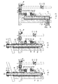
- a ventilation shaft 1 with a shaft wall 2 two pipes 14 and 15, supply air fan 3, air filter 4, maintenance cover 5 and exhaust fan 6. All of these parts are below a floor 7.
- Fig. 1 and 2 show a building with a pitched roof 17, wherein the shaft on the inside with heat and sound insulation 16 is equipped. 1 and 2, the exhaust air 11 is at an opening 22nd omitted at a roof outlet and the fresh or fresh air 10 at the same place let through an opening 21.
- a supply air line 8 and a supply air inlet 9 are also shown in all the figures, which can be provided with a grid.
- One or more can be in the ceiling, side wall or in the floor 7
- Supply air lines 8 must be installed. If the supply air inlet (s) 9 are in the same room, the supply air 10 flows as exhaust air 11 directly to the exhaust fan 6.
- the supply air 10 If the supply air 10 is supplied to another room of the use unit, it flows as overflow air 11 via overflow units 12 to the exhaust fan 6. Serve as a sound absorbing measure those arranged in the supply air line and the overflow unit 12 Silencer 13. To prevent unwanted air circulation There are 6 backflow flaps for the supply and exhaust fan 19 installed.
- the tubes 14 and 15 are preferably arranged coaxially one inside the other, have a circular cross-section, but can also have one any other cross-section, e.g. quadrangular.
- the Shaft usually extends through those used for these rooms Floors of the building from a point above the Flat or pitched roofs 17 to below and below the lowest vented room and ends there with a rain and condensate collector 18.
- the heat and sound insulation 16, the only is indicated in places, can also be used as fire and condensate protection insulation be trained.
- control of this facility can be extended for temporary operation and can be as a two-stage with or without a timer and another switching option for two or more Performance levels are expanded.
- the shaft 1 can be dimensioned such that there are also lines for heating, process water and waste water to let.
- a supply air inlet is in the accessible shaft wall 2 9 with air filter 4 and the exhaust fan 6 with air filter 4 and maintenance cover 5 installed.
- the supply air 10 flows as exhaust air 11 directly to the exhaust air fan 6. If the supply air 10 in another room of the use unit is supplied, this flows as overflow air 11 via overflow units 12 to the exhaust fan 6. For sound insulation are in the supply air line 8 and the overflow unit 12 arranged silencers 13 available. To prevent unwanted Air circulation is in the supply 3 and exhaust fan 6 backflow flaps 19 installed.
- the condensed water flows through the tubes 14, 15 down and is from the collector 24 with a connection to the dirty water.
- the fresh air 25 is used for preheating via an earth register 27 of the usual type sucked in and the exhaust air is led directly outside.
- the Control of the facility for this case takes place in one stage Continuous operation.
- control of this facility can be extended for temporary operation and can be as a two-stage with or without a timer and another switching option for two or more Performance levels are expanded.
Abstract
Description
Claims (9)
- Einrichtung zur Wärmerückgewinnung sowie zur Belüftung und Raumerwärmung mit Mitteln zum Wärmeaustausch zwischen zugeführter Frischluft und der aus dem Raum abgeführten Abluft in einem ein- oder mehrstöckigen Gebäude, wobei diese Mittel zwei ineinander angeordnete Rohre einschliessen und der Ringraum zwischen den Rohren für die Frischluftzufuhr und das innere Rohr für die Abluft ausgelegt ist, dadurch gekennzeichnet, dass die Rohre (14,15) in einem vertikalen Schacht (1) angeordnet sind, der auf der Innenseite mit einer Wärme- und Schallisolation (16) ausgekleidet ist, die auch als Brand- und Kondensatschutzisolation ausgebildet ist, dass Zuleitungen zu den einzelnen Zulufteintritten (9) von Schalldämpfern (13) gegen Strömungeräusche umgeben sind, und dass das untere Ende der vertikalen Rohre (14,15) mit einem lösbaren Abschlussdeckel (18,24) für den Kondensat-Auslass versehen ist.
- Einrichtung nach Anspruch 1, dadurch gekennzeichnet , dass sie zur Verbesserung des Wärmeaustausches zwischen den beiden Rohren (14,15) Leitbleche aufweist.
- Einrichtung nach Anspruch 1 oder 2, dadurch gekennzeichnet, dass sie zur zusätzlichen Erwärmung der Frischluft zusätzlich ein Register aufweist.
- Einrichtung nach Anspruch 1, 2 oder 3, dadurch gekennzeichnet, dass der Einlass für die Frischluft sowie der Auslass für die Abluft auf dem Dach des Gebäudes angeordnet sind.
- Einrichtung nach einem der Ansprüche 1 bis 3, dadurch gekennzeichnet, dass der Einlass für die Frischluft und der Auslass für die Abluft an einer Wandung des Gebäudes angeordnet sind.
- Einrichtung nach Anspruch 4 oder 5, dadurch gekennzeichnet, dass der Einlass und der Auslass derart beabstandet voneinander angeordnet sind, bzw. dass Einzugs- oder Blasrichtung derart festgelegt sind, dass die Abluft nicht an den Frischlufteinlass angezogen werden kann.
- Einrichtung nach einem der Ansprüche 1 bis 3, dadurch gekennzeichnet, dass der Einlass für die Frischluft in einem unter dem Gebäude verlaufenden Lüftungsschacht mit Verbindung zu einem Lufteinlass auf Erdbodenhöhe oder darüber angeordnet ist.
- Einrichtung nach einem der Ansprüche 1 bis 7, dadurch gekennzeichnet, dass der Einlass für die Frischluft und der Auslass für die Abluft über ein Erdregister angeordnet sind.
- Einrichtung nach einem der vorangehenden Ansprüche, dadurch gekennzeichnet, dass sie einen elektrischen Heizkörper am Einlass für die Frischluft zu deren zusätzlichen Erwärmung aufweist.
Priority Applications (3)
| Application Number | Priority Date | Filing Date | Title |
|---|---|---|---|
| DE50007682T DE50007682D1 (de) | 2000-02-23 | 2000-02-23 | Einrichtung zur Wärmerückgewinnung |
| EP00810151A EP1130332B1 (de) | 2000-02-23 | 2000-02-23 | Einrichtung zur Wärmerückgewinnung |
| AT00810151T ATE275717T1 (de) | 2000-02-23 | 2000-02-23 | Einrichtung zur wärmerückgewinnung |
Applications Claiming Priority (1)
| Application Number | Priority Date | Filing Date | Title |
|---|---|---|---|
| EP00810151A EP1130332B1 (de) | 2000-02-23 | 2000-02-23 | Einrichtung zur Wärmerückgewinnung |
Publications (2)
| Publication Number | Publication Date |
|---|---|
| EP1130332A1 true EP1130332A1 (de) | 2001-09-05 |
| EP1130332B1 EP1130332B1 (de) | 2004-09-08 |
Family
ID=8174563
Family Applications (1)
| Application Number | Title | Priority Date | Filing Date |
|---|---|---|---|
| EP00810151A Expired - Lifetime EP1130332B1 (de) | 2000-02-23 | 2000-02-23 | Einrichtung zur Wärmerückgewinnung |
Country Status (3)
| Country | Link |
|---|---|
| EP (1) | EP1130332B1 (de) |
| AT (1) | ATE275717T1 (de) |
| DE (1) | DE50007682D1 (de) |
Cited By (3)
| Publication number | Priority date | Publication date | Assignee | Title |
|---|---|---|---|---|
| DE102006048916A1 (de) * | 2006-10-17 | 2008-04-24 | Paukovic Pavao | Anlage und Verfahren zur Heizung/Kühlung von Familienhäusern mit Frischluft |
| DE102021105980A1 (de) | 2021-03-11 | 2022-09-15 | Werner Schallenberg | Luftführungseinrichtung zum Lüften und Entlüften eines Raumes gegenüber einer außerhalb des Raumes angeordneten Umgebung sowie Lüftungsanordnung mit einer Luftführungseinrichtung und einer Einrichtung zur kontrollierten Wohnraumlüftung |
| GB2617466A (en) * | 2022-04-05 | 2023-10-11 | Sano Development Ltd | Building ventilation system and method |
Families Citing this family (1)
| Publication number | Priority date | Publication date | Assignee | Title |
|---|---|---|---|---|
| CN110966704B (zh) * | 2019-12-19 | 2020-08-28 | 珠海大横琴科技发展有限公司 | 一种新风系统 |
Citations (6)
| Publication number | Priority date | Publication date | Assignee | Title |
|---|---|---|---|---|
| DE3006318A1 (de) * | 1980-02-20 | 1981-08-27 | Max-Schallschluck-Lüftungen GmbH & Co KG, 2000 Hamburg | Lueftervorrichtung |
| US4384609A (en) * | 1982-04-05 | 1983-05-24 | Neuzil Jack E | Earth/block air preconditioner |
| DE3310569A1 (de) | 1983-03-23 | 1984-09-27 | Robert Dipl.-Ing.(FH) 8000 München Spieldiener | Be- und entlueftungsanlage fuer mehrgeschossige bauwerke |
| DE3737579A1 (de) | 1987-11-05 | 1989-05-24 | Bosch Gmbh Robert | Anhaengerbremsventil |
| EP0533629A1 (de) | 1991-09-20 | 1993-03-24 | Wiba, Wintsch + Bach | Verfahren und Einrichtung zur Zufuhr von erwärmter Frischluft |
| FR2712851A1 (fr) * | 1993-11-23 | 1995-06-02 | Illbruck Sa | Conduit de ventilation comportant un atténuateur de bruit en mousse. |
-
2000
- 2000-02-23 AT AT00810151T patent/ATE275717T1/de not_active IP Right Cessation
- 2000-02-23 EP EP00810151A patent/EP1130332B1/de not_active Expired - Lifetime
- 2000-02-23 DE DE50007682T patent/DE50007682D1/de not_active Expired - Fee Related
Patent Citations (6)
| Publication number | Priority date | Publication date | Assignee | Title |
|---|---|---|---|---|
| DE3006318A1 (de) * | 1980-02-20 | 1981-08-27 | Max-Schallschluck-Lüftungen GmbH & Co KG, 2000 Hamburg | Lueftervorrichtung |
| US4384609A (en) * | 1982-04-05 | 1983-05-24 | Neuzil Jack E | Earth/block air preconditioner |
| DE3310569A1 (de) | 1983-03-23 | 1984-09-27 | Robert Dipl.-Ing.(FH) 8000 München Spieldiener | Be- und entlueftungsanlage fuer mehrgeschossige bauwerke |
| DE3737579A1 (de) | 1987-11-05 | 1989-05-24 | Bosch Gmbh Robert | Anhaengerbremsventil |
| EP0533629A1 (de) | 1991-09-20 | 1993-03-24 | Wiba, Wintsch + Bach | Verfahren und Einrichtung zur Zufuhr von erwärmter Frischluft |
| FR2712851A1 (fr) * | 1993-11-23 | 1995-06-02 | Illbruck Sa | Conduit de ventilation comportant un atténuateur de bruit en mousse. |
Cited By (6)
| Publication number | Priority date | Publication date | Assignee | Title |
|---|---|---|---|---|
| DE102006048916A1 (de) * | 2006-10-17 | 2008-04-24 | Paukovic Pavao | Anlage und Verfahren zur Heizung/Kühlung von Familienhäusern mit Frischluft |
| DE102021105980A1 (de) | 2021-03-11 | 2022-09-15 | Werner Schallenberg | Luftführungseinrichtung zum Lüften und Entlüften eines Raumes gegenüber einer außerhalb des Raumes angeordneten Umgebung sowie Lüftungsanordnung mit einer Luftführungseinrichtung und einer Einrichtung zur kontrollierten Wohnraumlüftung |
| GB2617466A (en) * | 2022-04-05 | 2023-10-11 | Sano Development Ltd | Building ventilation system and method |
| GB2617693A (en) * | 2022-04-05 | 2023-10-18 | Sano Development Ltd | Building ventilation system and method |
| GB2617693B (en) * | 2022-04-05 | 2024-04-17 | Sano Development Ltd | Building ventilation system and method |
| GB2617466B (en) * | 2022-04-05 | 2024-04-17 | Sano Development Ltd | Building ventilation system and method |
Also Published As
| Publication number | Publication date |
|---|---|
| EP1130332B1 (de) | 2004-09-08 |
| DE50007682D1 (de) | 2004-10-14 |
| ATE275717T1 (de) | 2004-09-15 |
Similar Documents
| Publication | Publication Date | Title |
|---|---|---|
| EP2342504A1 (de) | Modulares und fassaden-integriertes lüftungs- und klimasystem | |
| DE202004008792U1 (de) | Zentrales Lüftungssystem zur Lüftung eines Wohngebäudes | |
| EP1832818B1 (de) | Lüftungsanlage | |
| EP0533629B1 (de) | Verfahren und Einrichtung zur Zufuhr von erwärmter Frischluft | |
| DE202007008504U1 (de) | Vorrichtung zur Raumlüftung | |
| EP1130332B1 (de) | Einrichtung zur Wärmerückgewinnung | |
| DE202005000661U1 (de) | Umluftdecken-Modul | |
| WO2000031473A1 (de) | Vorrichtung und verfahren zum heizen und/oder lüften eines raumes | |
| EP1619447A2 (de) | Raumlüftungs- oder Raumklimagerät | |
| DE4134305C2 (de) | Frischluftanlage | |
| DE102017112777A1 (de) | Anordnung zur Belüftung eines Gebäudes | |
| EP2365248A1 (de) | Abgaskamin für Heizungsanlagen und Kaminrohr für einen Abgaskamin | |
| DE4135130C2 (de) | Be- und Entlüftungssystem für Wohnräume in Wohnungen | |
| DE20300465U1 (de) | Be- und Entlüftungsanlage mit Gegenstrombetrieb | |
| DE10255172A1 (de) | Raumlüftungsgerät | |
| EP1557618A2 (de) | Raumklimaeinrichtung | |
| DE102005003868B4 (de) | Vorrichtung zur Kondensatabführung in einer Brennwert-Heizungsanlage | |
| DE102009017053A1 (de) | Wärmetauschervorrichtung | |
| AT500559B1 (de) | Raumlufttechnische einrichtung | |
| DE102006048103A1 (de) | Wärmepumpe | |
| DE2757193A1 (de) | Fassadenelement | |
| DE10253264C5 (de) | Dezentrale lufttechnische Einrichtung sowie Verfahren zum dezentralen Heizen oder Kühlen eines Raumes | |
| EP1959205B1 (de) | Kompakte Inneneinheit als Fussbodeneinbaugerät | |
| DE102006039161B3 (de) | Saunakabine mit einem Abluftelement | |
| DE202005016955U1 (de) | Wärmepumpe |
Legal Events
| Date | Code | Title | Description |
|---|---|---|---|
| PUAI | Public reference made under article 153(3) epc to a published international application that has entered the european phase |
Free format text: ORIGINAL CODE: 0009012 |
|
| AK | Designated contracting states |
Kind code of ref document: A1 Designated state(s): AT BE CH CY DE DK ES FI FR GB GR IE IT LI LU MC NL PT SE |
|
| AX | Request for extension of the european patent |
Free format text: AL;LT;LV;MK;RO;SI |
|
| 17P | Request for examination filed |
Effective date: 20020228 |
|
| AKX | Designation fees paid |
Free format text: AT BE CH CY DE DK ES FI FR GB GR IE IT LI LU MC NL PT SE |
|
| 17Q | First examination report despatched |
Effective date: 20020523 |
|
| GRAP | Despatch of communication of intention to grant a patent |
Free format text: ORIGINAL CODE: EPIDOSNIGR1 |
|
| GRAS | Grant fee paid |
Free format text: ORIGINAL CODE: EPIDOSNIGR3 |
|
| GRAA | (expected) grant |
Free format text: ORIGINAL CODE: 0009210 |
|
| RAP1 | Party data changed (applicant data changed or rights of an application transferred) |
Owner name: BACH, URSULA |
|
| AK | Designated contracting states |
Kind code of ref document: B1 Designated state(s): AT CH CY DE DK ES FI FR GB GR IE IT LI LU MC NL PT SE |
|
| PG25 | Lapsed in a contracting state [announced via postgrant information from national office to epo] |
Ref country code: IT Free format text: LAPSE BECAUSE OF FAILURE TO SUBMIT A TRANSLATION OF THE DESCRIPTION OR TO PAY THE FEE WITHIN THE PRESCRIBED TIME-LIMIT;WARNING: LAPSES OF ITALIAN PATENTS WITH EFFECTIVE DATE BEFORE 2007 MAY HAVE OCCURRED AT ANY TIME BEFORE 2007. THE CORRECT EFFECTIVE DATE MAY BE DIFFERENT FROM THE ONE RECORDED. Effective date: 20040908 Ref country code: NL Free format text: LAPSE BECAUSE OF FAILURE TO SUBMIT A TRANSLATION OF THE DESCRIPTION OR TO PAY THE FEE WITHIN THE PRESCRIBED TIME-LIMIT Effective date: 20040908 Ref country code: GB Free format text: LAPSE BECAUSE OF FAILURE TO SUBMIT A TRANSLATION OF THE DESCRIPTION OR TO PAY THE FEE WITHIN THE PRESCRIBED TIME-LIMIT Effective date: 20040908 Ref country code: IE Free format text: LAPSE BECAUSE OF FAILURE TO SUBMIT A TRANSLATION OF THE DESCRIPTION OR TO PAY THE FEE WITHIN THE PRESCRIBED TIME-LIMIT Effective date: 20040908 Ref country code: FR Free format text: LAPSE BECAUSE OF FAILURE TO SUBMIT A TRANSLATION OF THE DESCRIPTION OR TO PAY THE FEE WITHIN THE PRESCRIBED TIME-LIMIT Effective date: 20040908 Ref country code: FI Free format text: LAPSE BECAUSE OF FAILURE TO SUBMIT A TRANSLATION OF THE DESCRIPTION OR TO PAY THE FEE WITHIN THE PRESCRIBED TIME-LIMIT Effective date: 20040908 |
|
| REG | Reference to a national code |
Ref country code: GB Ref legal event code: FG4D Free format text: NOT ENGLISH |
|
| REG | Reference to a national code |
Ref country code: CH Ref legal event code: EP |
|
| REG | Reference to a national code |
Ref country code: IE Ref legal event code: FG4D Free format text: GERMAN |
|
| REF | Corresponds to: |
Ref document number: 50007682 Country of ref document: DE Date of ref document: 20041014 Kind code of ref document: P |
|
| REG | Reference to a national code |
Ref country code: CH Ref legal event code: NV Representative=s name: PATENTANWAELTE FELDMANN & PARTNER AG |
|
| PG25 | Lapsed in a contracting state [announced via postgrant information from national office to epo] |
Ref country code: DK Free format text: LAPSE BECAUSE OF FAILURE TO SUBMIT A TRANSLATION OF THE DESCRIPTION OR TO PAY THE FEE WITHIN THE PRESCRIBED TIME-LIMIT Effective date: 20041208 Ref country code: GR Free format text: LAPSE BECAUSE OF FAILURE TO SUBMIT A TRANSLATION OF THE DESCRIPTION OR TO PAY THE FEE WITHIN THE PRESCRIBED TIME-LIMIT Effective date: 20041208 Ref country code: SE Free format text: LAPSE BECAUSE OF FAILURE TO SUBMIT A TRANSLATION OF THE DESCRIPTION OR TO PAY THE FEE WITHIN THE PRESCRIBED TIME-LIMIT Effective date: 20041208 |
|
| PG25 | Lapsed in a contracting state [announced via postgrant information from national office to epo] |
Ref country code: ES Free format text: LAPSE BECAUSE OF FAILURE TO SUBMIT A TRANSLATION OF THE DESCRIPTION OR TO PAY THE FEE WITHIN THE PRESCRIBED TIME-LIMIT Effective date: 20041219 |
|
| PG25 | Lapsed in a contracting state [announced via postgrant information from national office to epo] |
Ref country code: LU Free format text: LAPSE BECAUSE OF NON-PAYMENT OF DUE FEES Effective date: 20050223 Ref country code: CY Free format text: LAPSE BECAUSE OF FAILURE TO SUBMIT A TRANSLATION OF THE DESCRIPTION OR TO PAY THE FEE WITHIN THE PRESCRIBED TIME-LIMIT Effective date: 20050223 |
|
| PG25 | Lapsed in a contracting state [announced via postgrant information from national office to epo] |
Ref country code: MC Free format text: LAPSE BECAUSE OF NON-PAYMENT OF DUE FEES Effective date: 20050228 |
|
| NLV1 | Nl: lapsed or annulled due to failure to fulfill the requirements of art. 29p and 29m of the patents act | ||
| GBV | Gb: ep patent (uk) treated as always having been void in accordance with gb section 77(7)/1977 [no translation filed] |
Effective date: 20040908 |
|
| REG | Reference to a national code |
Ref country code: IE Ref legal event code: FD4D |
|
| PLBE | No opposition filed within time limit |
Free format text: ORIGINAL CODE: 0009261 |
|
| STAA | Information on the status of an ep patent application or granted ep patent |
Free format text: STATUS: NO OPPOSITION FILED WITHIN TIME LIMIT |
|
| 26N | No opposition filed |
Effective date: 20050609 |
|
| EN | Fr: translation not filed | ||
| REG | Reference to a national code |
Ref country code: CH Ref legal event code: PFA Owner name: BACH, URSULA Free format text: BACH, URSULA#ZUERICHERSTRASSE 44#8953 DIETIKON (CH) -TRANSFER TO- BACH, URSULA#ZUERICHERSTRASSE 44#8953 DIETIKON (CH) |
|
| PG25 | Lapsed in a contracting state [announced via postgrant information from national office to epo] |
Ref country code: PT Free format text: LAPSE BECAUSE OF NON-PAYMENT OF DUE FEES Effective date: 20050208 |
|
| PGFP | Annual fee paid to national office [announced via postgrant information from national office to epo] |
Ref country code: AT Payment date: 20090225 Year of fee payment: 10 |
|
| PGFP | Annual fee paid to national office [announced via postgrant information from national office to epo] |
Ref country code: DE Payment date: 20090225 Year of fee payment: 10 |
|
| PGFP | Annual fee paid to national office [announced via postgrant information from national office to epo] |
Ref country code: CH Payment date: 20090525 Year of fee payment: 10 |
|
| REG | Reference to a national code |
Ref country code: CH Ref legal event code: PL |
|
| PG25 | Lapsed in a contracting state [announced via postgrant information from national office to epo] |
Ref country code: LI Free format text: LAPSE BECAUSE OF NON-PAYMENT OF DUE FEES Effective date: 20100228 Ref country code: CH Free format text: LAPSE BECAUSE OF NON-PAYMENT OF DUE FEES Effective date: 20100228 |
|
| PG25 | Lapsed in a contracting state [announced via postgrant information from national office to epo] |
Ref country code: AT Free format text: LAPSE BECAUSE OF NON-PAYMENT OF DUE FEES Effective date: 20100223 |
|
| PG25 | Lapsed in a contracting state [announced via postgrant information from national office to epo] |
Ref country code: DE Free format text: LAPSE BECAUSE OF NON-PAYMENT OF DUE FEES Effective date: 20100901 |