EP1130217A1 - Befestigung von Laufschaufeln in einer Turbomaschine - Google Patents
Befestigung von Laufschaufeln in einer Turbomaschine Download PDFInfo
- Publication number
- EP1130217A1 EP1130217A1 EP00810175A EP00810175A EP1130217A1 EP 1130217 A1 EP1130217 A1 EP 1130217A1 EP 00810175 A EP00810175 A EP 00810175A EP 00810175 A EP00810175 A EP 00810175A EP 1130217 A1 EP1130217 A1 EP 1130217A1
- Authority
- EP
- European Patent Office
- Prior art keywords
- blade
- connecting piece
- feet
- opening
- roots
- Prior art date
- Legal status (The legal status is an assumption and is not a legal conclusion. Google has not performed a legal analysis and makes no representation as to the accuracy of the status listed.)
- Granted
Links
Images


Classifications
-
- F—MECHANICAL ENGINEERING; LIGHTING; HEATING; WEAPONS; BLASTING
- F01—MACHINES OR ENGINES IN GENERAL; ENGINE PLANTS IN GENERAL; STEAM ENGINES
- F01D—NON-POSITIVE DISPLACEMENT MACHINES OR ENGINES, e.g. STEAM TURBINES
- F01D5/00—Blades; Blade-carrying members; Heating, heat-insulating, cooling or antivibration means on the blades or the members
- F01D5/30—Fixing blades to rotors; Blade roots ; Blade spacers
- F01D5/32—Locking, e.g. by final locking blades or keys
-
- F—MECHANICAL ENGINEERING; LIGHTING; HEATING; WEAPONS; BLASTING
- F01—MACHINES OR ENGINES IN GENERAL; ENGINE PLANTS IN GENERAL; STEAM ENGINES
- F01D—NON-POSITIVE DISPLACEMENT MACHINES OR ENGINES, e.g. STEAM TURBINES
- F01D5/00—Blades; Blade-carrying members; Heating, heat-insulating, cooling or antivibration means on the blades or the members
- F01D5/30—Fixing blades to rotors; Blade roots ; Blade spacers
- F01D5/3023—Fixing blades to rotors; Blade roots ; Blade spacers of radial insertion type, e.g. in individual recesses
- F01D5/303—Fixing blades to rotors; Blade roots ; Blade spacers of radial insertion type, e.g. in individual recesses in a circumferential slot
- F01D5/3038—Fixing blades to rotors; Blade roots ; Blade spacers of radial insertion type, e.g. in individual recesses in a circumferential slot the slot having inwardly directed abutment faces on both sides
Definitions
- the invention relates to blades with blade feet, which in the circumferential grooves Rotor of a turbomachine are attached. It particularly affects hers Fastening and securing against twisting and falling out of the groove.
- a known way of moving blades on a rotor Assembling the turbo machine is anchoring using T-shaped shovel feet Circumferential grooves.
- To mount the blades in a circumferential groove To enable the last bucket in particular is a certain assembly game required in the circumferential direction. When operating the machine it can happen that the blades move and form a gap that is large it is enough that a blade root rotates and falls out of the groove. This Problem is solved by reducing the assembly play by between the bucket feet spacers are tightly installed, so that Assembly game is filled out. After installing the spacers that is however, remaining play between the blade feet is often too small to be free to allow thermal expansions. Because of the strains arise forces that disturb the smooth running of the rotor and finally vibrations can cause.
- the blade roots which are anchored in circumferential grooves, each have at least one depression or opening which runs in the circumferential direction and in which a connecting piece is arranged in each case, which connects at least two blade roots to one another to form a blade package.
- the blade feet thus connected are prevented from twisting.
- a connecting piece consists of a shaped piece of any cross section and is arranged in a recess or opening, the cross section of which is adapted to the shaped piece.
- the depression or opening and the shaped piece are dimensioned such that the shaped piece lies in a depression or opening with little play and a displacement of a blade root and the shaped piece relative to one another is still possible.
- the connecting piece consists of a shaped piece of rectangular cross section, which is inserted in a likewise rectangular depression on the side of the blade root which faces the rotor and the groove base.
- the connecting piece consists of a round wire which is inserted into a drilling opening in the blade root. Again, the diameter of the opening and of the wire is dimensioned such that the blade root can be moved along the wire.
- the blade feet each have a depression or opening which extends in the circumferential direction.
- the blade feet each have two parallel in the circumferential direction running recesses or openings, in each of which a connecting piece is inserted or inserted.
- a single connecting piece is arranged in one embodiment, which extends almost over the entire circumference of a groove and connects almost all blade roots in this groove to one another.
- shorter connecting pieces are arranged in the depressions or openings, each of which connects two or more adjacent blade roots to one another to form a blade package.
- Wells or openings are arranged short connecting pieces that Connect two blade feet to each other to form a pair of blade feet.
- Side by side and parallel connectors are around one Blade root offset from each other by a first connector in a first recess or opening is inserted and a first and adjacent, connects the second blade root.
- a second, parallel Connector is in the second, adjacent recess or opening inserted and connects the second and adjacent, third blade root, and immediately.
- the foot of the last shovel is placed in a mounting gap provided for it the groove is screwed in and secured against rotation by a connecting piece interlocked with the adjacent blade feet by a connector in the depression or opening of the last blade root is pulled in.
- blade attachment In a further embodiment of the blade attachment according to the invention is on the side of the blade root facing the groove base each in one Recess arranged a pressure spring, which causes displacement of the blade further reduced on the rotor, so that a gap formation and resulting aerodynamic disadvantages can be avoided.
- FIG. 1 shows a blade root 1 which is anchored in an inverse T-shaped circumferential groove 2 in a rotor 3 of a turbomachine.
- the blade root 1 has a recess 4 with a rectangular cross section on the side facing the groove base.
- a connector 5 with a similar rectangular cross section is inserted with a little play in the recess.
- the cross section of the recess in the blade root and the associated connecting piece is fundamentally arbitrary. Instead of the rectangular cross section for the depression and the connecting piece, for example, elliptical or round shapes can also be implemented.
- a round recess 6 is arranged, in which a compression spring 7 is inserted, which additionally prevents the blade root from being displaced.
- FIG. 1 shows a blade root 1 which is anchored in an inverse T-shaped circumferential groove 2 in a rotor 3 of a turbomachine.
- the blade root 1 has a recess 4 with a rectangular cross section on the side facing the groove base.
- FIG. 2 shows a view II of several adjacent blade feet 1 anchored in the circumferential groove, which are connected by a connecting piece 5. They form a package of blade feet which, thanks to their greater length, cannot twist in the circumferential groove, even if an assembly gap has arisen due to displacement of the blade feet during operation.
- the connecting piece thus provides an anti-rotation device, which prevents the blades from falling out.
- the blade roots along the entire circumferential groove are connected to one another to form several such blade root packages.
- a connection of almost all blade roots, with the exception of the last or two last blades, can also be carried out.
- FIG. 3 shows several blade roots anchored in a circumferential groove with a further arrangement of connecting pieces according to the invention.
- the blade roots 1, 1a, 1b, 1c, 1d each have two parallel depressions on their side facing the groove bottom, which are arranged on both sides of the blade root center.
- Short connecting pieces 5a, 5b, 5c are inserted in both recesses.
- Each connecting piece connects a pair of blade roots, the connecting pieces arranged in parallel next to each other being offset by one blade root.
- a connecting piece 5a is inserted in the first depression of the two blade feet 1a and 1b, connecting them and securing them against rotation.
- a second connecting piece 5b is inserted in the second, parallel recess of the blade roots 1b and 1c, connecting this pair of blade roots.
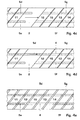
- FIG. 4a shows blade feet 11 and 12, which are spaced apart from the blade feet 13 and 14 by a mounting gap in the circumferential groove 2.
- the blade roots 11 and 12 are connected to one another by connecting pieces 5d and 5e. They both extend over several blade feet, for example.
- the blade feet 13 and 14 are connected and secured to one another by means of connecting pieces 5f and 5g.
- FIG. 4a shows blade feet 11 and 12, which are spaced apart from the blade feet 13 and 14 by a mounting gap in the circumferential groove 2.
- the blade roots 11 and 12 are connected to one another by connecting pieces 5d and 5e. They both extend over several blade feet, for example.
- the blade feet 13 and 14 are connected and secured to one another by means of connecting pieces 5f and 5g.
- FIGS. 4c-e shows the same circumferential groove 2 with the last blade, the blade root 15 of which has been anchored in the assembly gap of the groove 2.
- the depressions 4 of the blade root 15 are still empty here, so the blade root is not yet secured against rotation.
- the locking of this last blade root proceeds as follows according to FIGS. 4c-e: The blade root 12 is first pushed over the remaining gap next to the blade root 15, so that the ends of the connecting pieces 5d and 5e become visible. The connecting piece 5d is then pulled in the same direction until its end comes to rest in the recess 4 of the blade root 12.
- the assembly and locking is completed by slightly increasing the gaps between all the blade feet in the circumferential groove so that the gap that remains after the last blade has been installed is distributed over the entire circumferential groove.
- the intermediate pieces are a known component and are not shown here. They are dimensioned so that they reduce the assembly play and no longer a larger gap can form during turbine operation, which could disturb the smooth running of the rotor. Thanks to the anti-rotation device, however, they no longer have to completely fill up the assembly play, so that there is a sufficiently large free space between the blade feet, in which thermal expansion is freely allowed.
Landscapes
- Engineering & Computer Science (AREA)
- Mechanical Engineering (AREA)
- General Engineering & Computer Science (AREA)
- Turbine Rotor Nozzle Sealing (AREA)
Abstract
Description
Die Schaufelfüsse, welche in Umfangsnuten verankert sind, weisen erfindungsgemäss jeweils mindestens eine Vertiefung oder Öffnung auf, die in Umfangsrichtung verläuft und in denen jeweils ein Verbindungsstück angeordnet ist, das mindestens zwei Schaufelfüsse miteinander zu einem Schaufelpaket verbindet.
Die so verbundenen Schaufelfüsse werden dadurch an einer Verdrehung gehindert. Ein Verbindungsstück besteht aus einem Formstück eines beliebigen Querschnitts, und ist in einer Vertiefung oder Öffnung angeordnet, dessen Querschnitt dem Formstück angepasst ist. Dabei ist die Vertiefung oder Öffnung sowie das Formstück so dimensioniert, dass das Formstück mit kleinem Spiel in einer Vertiefung oder Öffnung liegt und eine Verschiebung eines Schaufelfusses und des Formstücks relativ zueinander noch möglich ist.
In einer zweiten Ausführung der Erfindung besteht das Verbindungsstück aus einem runden Draht, der in einer Bohr-Öffnung im Schaufelfuss eingeschoben ist. Wiederum ist der Durchmesser der Öffnung und des Drahtes so dimensioniert, dass eine Verschiebung des Schaufelfusses entlang dem Draht möglich ist.
In einer weiteren Ausführung sind in den Vertiefungen oder Öffnungen kürzere Verbindungsstücke angeordnet, die jeweils zwei oder mehrere benachbarte Schaufelfüsse miteinander zu einem Schaufelpaket verbinden.
In der Mitte der dem Nutboden zugewandten Seite des Schaufelfusses ist eine runde Vertiefung 6 angeordnet, in der eine Pressfeder 7 eingelegt ist, die den Schaufelfuss zusätzlich an Verschiebungen hindert.
Figur 2 zeigt eine Ansicht II von mehreren benachbarten, in der Umfangsnut verankerten Schaufelfüssen 1, die durch ein Verbindungsstück 5 verbunden sind. Sie bilden ein Paket von Schaufelfüssen, welches sich in der Umfangsnut dank ihrer grösseren Länge nicht verdrehen kann, auch wenn durch Verschiebung der Schaufelfüsse während des Betriebs ein Montagespalt entstanden ist. Das Verbindungsstück gewährt somit eine Verdrehsicherung, die ein Herausfallen der Schaufeln verunmöglicht.
Die Schaufelfüsse entlang der gesamten Umfangsnut werden auf diese Art zu mehreren solcher Schaufelfuss-Paketen miteinander verbunden. Eine Verbindung von fast allen Schaufelfüssen, mit Ausnahme der letzten oder zwei letzten Schaufeln, durch ein einziges Verbindungsstück, ist ebenfalls ausführbar.
In den Figuren 4a bis 4e ist die Montage der letzten Schaufel der Umfangsnut und die Verriegelung ihres Schaufelfusses mit den benachbarten Schaufelfüssen mittels den erfindungsgemässen Verbindungsstücken dargestellt.
Figur 4a zeigt Schaufelfüsse 11 und 12, die von den Schaufelfüssen 13 und 14 durch einen Montagespalt in der Umfangsnut 2 beabstandet sind. Die Schaufelfüsse 11 und 12 sind mit Verbindungsstücken 5d und 5e miteinander verbunden. Sie erstrecken sich beide beispielsweise über mehrere Schaufelfüsse. Die Schaufelfüsse 13 und 14 sind mittels Verbindungsstücken 5f und 5g miteinander verbunden und gesichert.
Figur 4b zeigt dieselbe Umfangsnut 2 mit der letzten Schaufel, deren Schaufelfuss 15 in dem Montagespalt der Nut 2 verankert worden ist. Die Vertiefungen 4 des Schaufelfusses 15 sind hier noch leer, der Schaufelfuss also noch nicht gegen Verdrehung gesichert. Die Verriegelung dieses letzten Schaufelfusses verläuft wie folgt gemäss den Figuren 4c-e: Der Schaufelfuss 12 wird zunächst über den verbleibenden Spalt hinweg neben den Schaufelfuss 15 geschoben, sodass die Enden der Verbindungsstücke 5d und 5e sichtbar werden. Das Verbindungsstück 5d wird sodann in dieselbe Richtung gezogen bis sein Ende in der Vertiefung 4 des Schaufelfusses 12 zu liegen kommt. Die Montage und Verriegelung wird vervollständigt, indem die Spalten zwischen sämtlichen Schaufelfüssen in der Umfangsnut leicht vergrössert werden, sodass der Spalt, der nach der Montage der letzten Schaufel verblieben ist, über die ganze Umfangsnut verteilt wird. Mittels Zwischenstücken werden diese verbleibenden Spalten aufgefüllt.
Es resultiert, dass fast alle Schaufelfüsse mittels zwei parallel verlaufenden Verbindungsstücken gegen Verdrehung gesichert sind und die übrigen Schaufelfüsse zumindest mittels einem Verbindungsstück gesichert sind. Dadurch ist gewährleistet, dass keine der Schaufeln sich verdrehen und aus der Nut fallen kann.
Die Zwischenstücke sind ein bekanntes Bauteil und sind hier nicht dargestellt. Sie sind so dimensioniert, dass sie das Montagespiel verkleinern und sich während des Turbinenbetriebs kein grösserer Spalt mehr bilden kann, welcher die Laufruhe des Rotors stören könnte. Dank der Verdrehsicherung brauchen sie das Montagespiel jedoch nicht mehr restlos aufzufüllen, sodass zwischen den Schaufelfüssen ein genügend grosser freier Raum verbleibt, in dem thermische Dehnungen frei gewährt sind.
- 1, 1a-1d, 11-15
- Schaufelfuss
- 2
- Umfangsnut
- 3
- Rotor
- 4
- Vertiefung
- 5, 5a-g
- Verbindungsstück
- 6
- Vertiefung
- 7
- Anpressfeder
Claims (9)
- Befestigung von Laufschaufeln am Rotor (3) einer Turbomaschine, wobei die Laufschaufeln jeweils einen Schaufelfuss (1) aufweisen, der in einer Umfangsnut (2) verankert ist,
dadurch gekennzeichnet, dass
die Schaufelfüsse (1) jeweils mindestens eine Vertiefung (4) oder Öffnung aufweisen, wobei die Vertiefung oder Öffnung in Umfangsrichtung verläuft und in der Vertiefung oder Öffnung jeweils ein Verbindungsstück (5) angeordnet ist, das der Form der Vertiefung (4) oder Öffnung angepasst ist, und das Verbindungsstück mindestens zwei Schaufelfüsse(1) zu einem Schaufelfuss-Paket verbindet. - Befestigung von Laufschaufeln nach Anspruch 1,
dadurch gekennzeichnet, dass
die Schaufelfüsse (1) jeweils zwei Vertiefungen (4) oder Öffnungen aufweisen, in die je ein Verbindungsstück angeordnet ist. - Befestigung von Laufschaufeln nach Anspruch 1 oder 2,
dadurch gekennzeichnet, dass
die mindestens eine Vertiefung (4) jeweils an der dem Nutboden der Umfangsnut (2) zugewandten Seite des Schaufelfusses (1) angeordnet ist und einen rechteckigen Querschnitt aufweist und das Verbindungsstück (5), das jeweils in die mindestens eine Vertiefung (4) eingelegt ist, ein Formstück von gleichem rechteckigem Querschnitt ist. - Befestigung von Laufschaufeln nach Anspruch 1 oder 2,
dadurch gekennzeichnet, dass
die Öffnung am Schaufelfuss (1) eine Bohröffnung ist und das Verbindungsstück aus einem Draht von gleichem Durchmesser besteht, das in die Bohröffnung eingeschoben ist. - Befestigung von Laufschaufeln nach einem der Ansprüche 1 bis 4,
dadurch gekennzeichnet, dass
die Verbindungsstücke (5) sich fast über den gesamten Nutumfang erstrecken und fast alle Schaufelfüsse (1) zu einem Schaufelpaket verbinden. - Befestigung von Laufschaufeln nach einem der Ansprüche 1 bis 4,
dadurch gekennzeichnet, dass
die Verbindungsstücke (5) sich über zwei oder mehrere Schaufelfüsse (1) erstrecken und diese zu mehreren Schaufelpaketen verbinden. - Befestigung von Laufschaufeln nach Anspruch 6,
dadurch gekennzeichnet, dass
die Schaufelfüsse (2) jeweils zwei Vertiefungen (4) oder Öffnungen aufweisen und die Verbindungsstücke (5) sich jeweils über zwei Schaufelfüsse (1) erstrecken und die parallel nebeneinander angeordneten Verbindungsstücke um einen Schaufelfuss versetzt angeordnet sind. - Befestigung von Laufschaufeln nach einem der Ansprüche 1 bis 7,
dadurch gekennzeichnet, dass
die Schaufelfüsse (1) jeweils eine runde Vertiefung (6) aufweisen, in der eine Anpressfeder (7) angeordnet ist. - Befestigung von Laufschaufeln nach einem der Ansprüche 1 bis 7,
dadurch gekennzeichnet, dass
der letzte in die Umfangsnut (2) montierte Schaufelfuss (1) durch Verschieben von einem oder zwei Verbindungsstücken (5d, 5e) mit den benachbarten Schaufelfüssen verriegelt ist.
Priority Applications (3)
| Application Number | Priority Date | Filing Date | Title |
|---|---|---|---|
| DE50010348T DE50010348D1 (de) | 2000-03-01 | 2000-03-01 | Befestigung von Laufschaufeln in einer Turbomaschine |
| EP00810175A EP1130217B1 (de) | 2000-03-01 | 2000-03-01 | Befestigung von Laufschaufeln in einer Turbomaschine |
| US09/794,050 US20010019697A1 (en) | 2000-03-01 | 2001-02-28 | Fastening rotor blades in a turbomachine |
Applications Claiming Priority (1)
| Application Number | Priority Date | Filing Date | Title |
|---|---|---|---|
| EP00810175A EP1130217B1 (de) | 2000-03-01 | 2000-03-01 | Befestigung von Laufschaufeln in einer Turbomaschine |
Publications (2)
| Publication Number | Publication Date |
|---|---|
| EP1130217A1 true EP1130217A1 (de) | 2001-09-05 |
| EP1130217B1 EP1130217B1 (de) | 2005-05-18 |
Family
ID=8174578
Family Applications (1)
| Application Number | Title | Priority Date | Filing Date |
|---|---|---|---|
| EP00810175A Expired - Lifetime EP1130217B1 (de) | 2000-03-01 | 2000-03-01 | Befestigung von Laufschaufeln in einer Turbomaschine |
Country Status (3)
| Country | Link |
|---|---|
| US (1) | US20010019697A1 (de) |
| EP (1) | EP1130217B1 (de) |
| DE (1) | DE50010348D1 (de) |
Cited By (5)
| Publication number | Priority date | Publication date | Assignee | Title |
|---|---|---|---|---|
| EP1707746A1 (de) * | 2005-03-18 | 2006-10-04 | Siemens Aktiengesellschaft | Maschinenteil einer Strömungsmaschine, Strömungsmaschine und Verfahren zur Montage von Schaufeln bei einem Maschinenteil |
| EP2320030A1 (de) * | 2009-11-10 | 2011-05-11 | Alstom Technology Ltd | Rotor mit Laufschaufel für eine axial durchströmte Turbomaschine |
| CH702203A1 (de) * | 2009-11-10 | 2011-05-13 | Alstom Technology Ltd | Rotor für eine axial durchströmte turbomaschine sowie laufschaufel für einen solchen rotor. |
| EP2562356A1 (de) * | 2011-08-24 | 2013-02-27 | Siemens Aktiengesellschaft | Schaufelanordnung |
| EP4209658A1 (de) * | 2022-01-05 | 2023-07-12 | General Electric Company | Verdichterkomponente mit rückhaltefeder |
Families Citing this family (6)
| Publication number | Priority date | Publication date | Assignee | Title |
|---|---|---|---|---|
| WO2005010323A1 (de) * | 2003-07-26 | 2005-02-03 | Alstom Technology Ltd | Schaufelfussbefestigung für eine turbomaschine |
| US7474643B2 (en) * | 2003-10-02 | 2009-01-06 | Qualcomm Incorporated | Systems and methods for communicating control data using multiple slot formats |
| EP2045444B1 (de) * | 2007-10-01 | 2015-11-18 | Alstom Technology Ltd | Laufschaufel, Verfahren zur Herstellung einer Laufschaufel, sowie Verdichter mit einer solchen Laufschaufel |
| DE102010053141B4 (de) * | 2009-12-07 | 2018-10-11 | General Electric Technology Gmbh | Turbinenaggregat mit möglicher Überdrehung des Fußes einer Schaufel bis zum Einbau einer letzten Schaufel |
| GB201203303D0 (en) | 2012-02-27 | 2012-04-11 | Rolls Royce Plc | Balancing of rotor |
| KR20230091604A (ko) | 2021-12-16 | 2023-06-23 | 한화에어로스페이스 주식회사 | 보호심을 구비하는 로터 어셈블리 및 이를 포함하는 가스 터빈 엔진 |
Citations (7)
| Publication number | Priority date | Publication date | Assignee | Title |
|---|---|---|---|---|
| DE333353C (de) * | 1920-04-16 | 1921-03-18 | Osthoff Fa Walter | Gewebe-Gassengmaschine |
| DE459203C (de) * | 1928-04-27 | E H Hans Holzwarth Dr Ing | Einrichtung zur Schaufelbefestigung fuer Dampf- und Gasturbinen | |
| GB614678A (en) * | 1946-07-19 | 1948-12-20 | Parsons C A & Co Ltd | Improvements in or relating to turbine blading or the like |
| US2809801A (en) * | 1952-04-18 | 1957-10-15 | Ingersoll Rand Co | Turbine rotor construction |
| DE1751819B1 (de) * | 1968-07-26 | 1971-01-21 | Sulzer Ag | Läufer für Str¦mungsmaschinen |
| EP0530097A1 (de) * | 1991-08-28 | 1993-03-03 | Societe Nationale D'etude Et De Construction De Moteurs D'aviation "Snecma" | Turbomaschinenrotor mit Winkelpositionierung der Schaufeln |
| US5509784A (en) * | 1994-07-27 | 1996-04-23 | General Electric Co. | Turbine bucket and wheel assembly with integral bucket shroud |
-
2000
- 2000-03-01 DE DE50010348T patent/DE50010348D1/de not_active Expired - Lifetime
- 2000-03-01 EP EP00810175A patent/EP1130217B1/de not_active Expired - Lifetime
-
2001
- 2001-02-28 US US09/794,050 patent/US20010019697A1/en not_active Abandoned
Patent Citations (7)
| Publication number | Priority date | Publication date | Assignee | Title |
|---|---|---|---|---|
| DE459203C (de) * | 1928-04-27 | E H Hans Holzwarth Dr Ing | Einrichtung zur Schaufelbefestigung fuer Dampf- und Gasturbinen | |
| DE333353C (de) * | 1920-04-16 | 1921-03-18 | Osthoff Fa Walter | Gewebe-Gassengmaschine |
| GB614678A (en) * | 1946-07-19 | 1948-12-20 | Parsons C A & Co Ltd | Improvements in or relating to turbine blading or the like |
| US2809801A (en) * | 1952-04-18 | 1957-10-15 | Ingersoll Rand Co | Turbine rotor construction |
| DE1751819B1 (de) * | 1968-07-26 | 1971-01-21 | Sulzer Ag | Läufer für Str¦mungsmaschinen |
| EP0530097A1 (de) * | 1991-08-28 | 1993-03-03 | Societe Nationale D'etude Et De Construction De Moteurs D'aviation "Snecma" | Turbomaschinenrotor mit Winkelpositionierung der Schaufeln |
| US5509784A (en) * | 1994-07-27 | 1996-04-23 | General Electric Co. | Turbine bucket and wheel assembly with integral bucket shroud |
Cited By (9)
| Publication number | Priority date | Publication date | Assignee | Title |
|---|---|---|---|---|
| EP1707746A1 (de) * | 2005-03-18 | 2006-10-04 | Siemens Aktiengesellschaft | Maschinenteil einer Strömungsmaschine, Strömungsmaschine und Verfahren zur Montage von Schaufeln bei einem Maschinenteil |
| EP2320030A1 (de) * | 2009-11-10 | 2011-05-11 | Alstom Technology Ltd | Rotor mit Laufschaufel für eine axial durchströmte Turbomaschine |
| CH702203A1 (de) * | 2009-11-10 | 2011-05-13 | Alstom Technology Ltd | Rotor für eine axial durchströmte turbomaschine sowie laufschaufel für einen solchen rotor. |
| US8770938B2 (en) | 2009-11-10 | 2014-07-08 | Alstom Technology Ltd | Rotor for an axial-throughflow turbomachine and moving blade for such a rotor |
| EP2562356A1 (de) * | 2011-08-24 | 2013-02-27 | Siemens Aktiengesellschaft | Schaufelanordnung |
| WO2013026735A1 (de) * | 2011-08-24 | 2013-02-28 | Siemens Aktiengesellschaft | Schaufelanordnung |
| CN104053858B (zh) * | 2011-08-24 | 2016-02-17 | 西门子公司 | 叶片装置 |
| US9708919B2 (en) | 2011-08-24 | 2017-07-18 | Siemens Aktiengesellschaft | Blade arrangement |
| EP4209658A1 (de) * | 2022-01-05 | 2023-07-12 | General Electric Company | Verdichterkomponente mit rückhaltefeder |
Also Published As
| Publication number | Publication date |
|---|---|
| EP1130217B1 (de) | 2005-05-18 |
| DE50010348D1 (de) | 2005-06-23 |
| US20010019697A1 (en) | 2001-09-06 |
Similar Documents
| Publication | Publication Date | Title |
|---|---|---|
| EP1130217A1 (de) | Befestigung von Laufschaufeln in einer Turbomaschine | |
| DE69413639T2 (de) | Vorrichtung für die Verbindung von zwei Tunnelelementen | |
| EP0007397A1 (de) | Verbindungsbeschlag | |
| DE7438208U (de) | Kupplung, insbesondere zur verwendung bei turbogeneratoren | |
| DE2724003B2 (de) | Schaufelverriegelung im Stator eines Axialkompressorgehäuses | |
| DE1576979B2 (de) | Läufer für Strömungsmaschinen | |
| DE3818362C2 (de) | Rohrschelle | |
| DE2937244A1 (de) | Wellen-naben-verbindung | |
| EP1028231B1 (de) | Befestigung von Laufschaufeln einer Strömungsmachine | |
| DE3341871A1 (de) | Axialverdichter | |
| EP1552149B1 (de) | Stator für exzenterschneckenpumpen | |
| DE602005001231T2 (de) | Verriegelungsmittel für Gasturbinentriebwerke | |
| DE2930578C3 (de) | Buchse aus elastischem Material für eine Verbindung | |
| DE1954318B2 (de) | Vorrichtung zur Lagerung der Kurbelwelle am Gestell eines Reihenoder V-Motors | |
| EP1382509B1 (de) | Lenksäule | |
| DE3248021A1 (de) | Fuellstueck zur arretierung eines schaufelkranzes in einer schaufelhaltenut eines stroemungsmaschinenrotors | |
| DE2906703B2 (de) | Laschenkette mit abwechselnd Einlaschengliedern und Doppellaschengliedern | |
| DE3223994C2 (de) | Axialsicherungselement | |
| DE1947065A1 (de) | Sicherheitsentkupplungswelle | |
| DE19823157A1 (de) | Einrichtung zur Befestigung der Laufschaufeln axial durchströmter Turbomaschinen | |
| WO2003044926A2 (de) | Dynamoelektrische maschine mit verkeilten wicklungsstäben | |
| DE69002193T2 (de) | Rotor. | |
| DE2601394A1 (de) | Scheiteldichtung | |
| DE4312340C2 (de) | Dübel | |
| EP0940587B1 (de) | Befestigungsvorrichtung |
Legal Events
| Date | Code | Title | Description |
|---|---|---|---|
| PUAI | Public reference made under article 153(3) epc to a published international application that has entered the european phase |
Free format text: ORIGINAL CODE: 0009012 |
|
| AK | Designated contracting states |
Kind code of ref document: A1 Designated state(s): AT BE CH CY DE DK ES FI FR GB GR IE IT LI LU MC NL PT SE Kind code of ref document: A1 Designated state(s): DE GB |
|
| AX | Request for extension of the european patent |
Free format text: AL;LT;LV;MK;RO;SI |
|
| RAP1 | Party data changed (applicant data changed or rights of an application transferred) |
Owner name: ALSTOM (SWITZERLAND) LTD |
|
| RAP1 | Party data changed (applicant data changed or rights of an application transferred) |
Owner name: ALSTOM (SWITZERLAND) LTD |
|
| AKX | Designation fees paid | ||
| REG | Reference to a national code |
Ref country code: DE Ref legal event code: 8566 |
|
| 17P | Request for examination filed |
Effective date: 20020506 |
|
| RBV | Designated contracting states (corrected) |
Designated state(s): DE GB |
|
| RAP1 | Party data changed (applicant data changed or rights of an application transferred) |
Owner name: ALSTOM TECHNOLOGY LTD |
|
| 17Q | First examination report despatched |
Effective date: 20040616 |
|
| GRAP | Despatch of communication of intention to grant a patent |
Free format text: ORIGINAL CODE: EPIDOSNIGR1 |
|
| GRAS | Grant fee paid |
Free format text: ORIGINAL CODE: EPIDOSNIGR3 |
|
| GRAA | (expected) grant |
Free format text: ORIGINAL CODE: 0009210 |
|
| AK | Designated contracting states |
Kind code of ref document: B1 Designated state(s): DE GB |
|
| REG | Reference to a national code |
Ref country code: GB Ref legal event code: FG4D Free format text: NOT ENGLISH |
|
| REF | Corresponds to: |
Ref document number: 50010348 Country of ref document: DE Date of ref document: 20050623 Kind code of ref document: P |
|
| GBT | Gb: translation of ep patent filed (gb section 77(6)(a)/1977) |
Effective date: 20050803 |
|
| PLBE | No opposition filed within time limit |
Free format text: ORIGINAL CODE: 0009261 |
|
| STAA | Information on the status of an ep patent application or granted ep patent |
Free format text: STATUS: NO OPPOSITION FILED WITHIN TIME LIMIT |
|
| 26N | No opposition filed |
Effective date: 20060221 |
|
| PGFP | Annual fee paid to national office [announced via postgrant information from national office to epo] |
Ref country code: GB Payment date: 20130225 Year of fee payment: 14 |
|
| PGFP | Annual fee paid to national office [announced via postgrant information from national office to epo] |
Ref country code: DE Payment date: 20130328 Year of fee payment: 14 |
|
| REG | Reference to a national code |
Ref country code: DE Ref legal event code: R119 Ref document number: 50010348 Country of ref document: DE |
|
| GBPC | Gb: european patent ceased through non-payment of renewal fee |
Effective date: 20140301 |
|
| REG | Reference to a national code |
Ref country code: DE Ref legal event code: R119 Ref document number: 50010348 Country of ref document: DE Effective date: 20141001 |
|
| PG25 | Lapsed in a contracting state [announced via postgrant information from national office to epo] |
Ref country code: GB Free format text: LAPSE BECAUSE OF NON-PAYMENT OF DUE FEES Effective date: 20140301 Ref country code: DE Free format text: LAPSE BECAUSE OF NON-PAYMENT OF DUE FEES Effective date: 20141001 |