EP1130184A2 - Stahlbeton-Stütze - Google Patents
Stahlbeton-Stütze Download PDFInfo
- Publication number
- EP1130184A2 EP1130184A2 EP01104125A EP01104125A EP1130184A2 EP 1130184 A2 EP1130184 A2 EP 1130184A2 EP 01104125 A EP01104125 A EP 01104125A EP 01104125 A EP01104125 A EP 01104125A EP 1130184 A2 EP1130184 A2 EP 1130184A2
- Authority
- EP
- European Patent Office
- Prior art keywords
- steel
- support according
- strength
- concrete
- column
- Prior art date
- Legal status (The legal status is an assumption and is not a legal conclusion. Google has not performed a legal analysis and makes no representation as to the accuracy of the status listed.)
- Granted
Links
- 229910000831 Steel Inorganic materials 0.000 claims abstract description 16
- 239000010959 steel Substances 0.000 claims abstract description 16
- 239000011372 high-strength concrete Substances 0.000 claims abstract description 9
- 238000003466 welding Methods 0.000 claims abstract description 4
- 239000004567 concrete Substances 0.000 claims description 8
- 239000000835 fiber Substances 0.000 claims description 7
- 230000002787 reinforcement Effects 0.000 claims description 7
- 239000011150 reinforced concrete Substances 0.000 claims description 6
- 241000277275 Oncorhynchus mykiss Species 0.000 claims description 3
- 238000004026 adhesive bonding Methods 0.000 claims description 3
- 230000008018 melting Effects 0.000 claims description 2
- 238000002844 melting Methods 0.000 claims description 2
- 239000000945 filler Substances 0.000 claims 1
- 239000000463 material Substances 0.000 abstract description 2
- 230000003014 reinforcing effect Effects 0.000 abstract 4
- XLYOFNOQVPJJNP-UHFFFAOYSA-N water Substances O XLYOFNOQVPJJNP-UHFFFAOYSA-N 0.000 description 4
- 239000004568 cement Substances 0.000 description 2
- 230000001066 destructive effect Effects 0.000 description 1
- 238000009792 diffusion process Methods 0.000 description 1
- 238000011065 in-situ storage Methods 0.000 description 1
- 239000007788 liquid Substances 0.000 description 1
- 238000004519 manufacturing process Methods 0.000 description 1
Images
Classifications
-
- E—FIXED CONSTRUCTIONS
- E04—BUILDING
- E04C—STRUCTURAL ELEMENTS; BUILDING MATERIALS
- E04C3/00—Structural elongated elements designed for load-supporting
- E04C3/30—Columns; Pillars; Struts
- E04C3/34—Columns; Pillars; Struts of concrete other stone-like material, with or without permanent form elements, with or without internal or external reinforcement, e.g. metal coverings
-
- E—FIXED CONSTRUCTIONS
- E04—BUILDING
- E04C—STRUCTURAL ELEMENTS; BUILDING MATERIALS
- E04C5/00—Reinforcing elements, e.g. for concrete; Auxiliary elements therefor
- E04C5/01—Reinforcing elements of metal, e.g. with non-structural coatings
- E04C5/06—Reinforcing elements of metal, e.g. with non-structural coatings of high bending resistance, i.e. of essentially three-dimensional extent, e.g. lattice girders
- E04C5/0604—Prismatic or cylindrical reinforcement cages composed of longitudinal bars and open or closed stirrup rods
Definitions
- the invention relates to a reinforced concrete column.
- support describes rod-shaped pressure element, the larger cross-sectional dimension of which is four times does not exceed the smaller dimension.
- the invention has for its object a maximum payload at the smallest Develop cross-sectional reinforced concrete column, if necessary can also be delivered as a finished part.
- this object is achieved by a reinforced concrete column, consisting of high-strength concrete and one made of high-strength steel Longitudinal reinforcement with a steel head or base plate non-positively connected by gluing or spot welding are, and with a stirrup or spiral reinforcement.
- high-strength concrete denotes concrete of strength classes C55 / 67 - C100 / 115 with a dry bulk density of over 2,100 kg / m 3 , but at most 2,600 kg / m 3 (according to DIN 1045-2) .
- high-strength concretes are those that exceed the strength class C 50/60 according to DIN 1045, for example a C 80/95.
- high-strength concretes with a very low water / cement value of generally less than 0.40 are produced.
- Such concretes are impermeable to liquid water, and the diffusion of water vapor is very slow and depends on the balance. Depending on the ambient conditions, in particular the relative air humidity, a moisture equilibrium is established in the concrete, so that the concrete generally contains more than 3% by weight of water.
- the high-strength steel to be used according to the invention is preferably not cold-drawn and has a quality> S 500.
- Steel S 835/1030 according to DIN EN 10138, part 4 is preferably used; this has a nominal tensile strength of at least 1030 N / mm 2 . According to the invention, therefore, no structural steels are used, but steels of greater strength. High-strength ribbed longitudinal bars but also smooth steels can be used.
- this can be done by adding steel fibers or chips Brittle fracture behavior of the high-strength concrete can be improved. You can these steel fibers or chips have a length of 25 - 60 mm.
- the concrete is an addition of plastic fibers contains by softening, melting or decomposing at temperatures can form a capillary system from 150 - 300 ° C. It is already known and by DE 42 20 274 C2 and EP 0 575 886 B1 Protection provided by the addition of such fibers in components made of high-strength Emphasize, especially reinforced concrete components, the destructive flaking under To prevent fire exposure.
- the capillary system mentioned essentially linear capillary with a diameter between 10 and 100 m and a length between 5 and 35 mm.
- a support according to the invention can extend over one or more storey heights have extending length. It is useful if one in each case at the level of a storey, possibly with one Filling material filled bag is provided.
- the supports according to the invention are preferably used as prefabricated elements concreted and compacted horizontally. Basically, however, is also a manufacture possible as in-situ concrete column.
- the high-strength concrete applies to both the load capacity as well as in the event of fire together with the high-strength steel Carries or survives loads or stresses from fire.
- the invention also detects columns that do not have connecting reinforcement, but only be fixed in place with a oarlock.
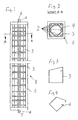
- Figure 1 shows a reinforced concrete column 1 with a longitudinal reinforcement made of high strength Steel.
- Longitudinal bars 2 are provided, that of outer brackets 3 and inner ones Brackets 4 are encompassed, which are somewhat denser in the area of the support ends are arranged as above the central longitudinal section of the support 1.
- the concrete cover is identified by reference number 5.
- the longitudinal bars 2 have a steel head plate 6 at the ends of the supports or base plate 7 non-positively connected by gluing or spot welding.
- An oar 8 can also be attached to fix the position.
Landscapes
- Engineering & Computer Science (AREA)
- Architecture (AREA)
- Civil Engineering (AREA)
- Structural Engineering (AREA)
- Reinforcement Elements For Buildings (AREA)
- Rod-Shaped Construction Members (AREA)
- Joining Of Building Structures In Genera (AREA)
Abstract
Description
- Figur 1
- eine Stütze im lotrechten Schnitt;
- Figur 2
- einen Schnitt gemäß der Linie A-A der Figur 1;
- Figur 3
- einen äußeren Bügel der Bewehrung in Draufsicht und
- Figur 4
- in einer Darstellung gemäß Figur 3 einen inneren Bügel.
Claims (8)
- Stahlbeton-Stütze, bestehend aus hochfestem Beton und einer aus hochfestem Stahl bestehenden Längsbewehrung (2), die an den Stützenenden mit einer stählernen Kopf- bzw. Fußplatte (6, 7) durch Anklebung oder Punktschweißung kraftschlüssig verbunden sind, und mit einer Bügel- bzw. Wendelbewehrung (3, 4).
- Stütze nach Anspruch 1, gekennzeichnet durch einen hochfesten Beton einer Güte > C 50/60, vorzugsweise der Festigkeitsklasse C 100/115.
- Stütze nach Anspruch 1 oder 2, gekennzeichnet durch einen hochfesten Stahl mit einer Güte > S 500.
- Stütze nach Anspruch 1, 2 oder 3, gekennzeichnet durch einen Zusatz von Stahlfasern oder Stahlspänen.
- Stütze nach Anspruch 4, dadurch gekennzeichnet, dass die Stahlfasern oder Stahlspäne eine Länge von 25 - 60 mm aufweisen.
- Stütze nach einem der vorhergehenden Ansprüche, dadurch gekennzeichnet, dass der Beton Kunststofffasern enthält, die durch Erweichen, Schmelzen oder Zersetzen bei Temperaturen von 150 - 300°C ein Kapillarsystem ausbilden können.
- Stütze nach einem der vorhergehenden Ansprüche, gekennzeichnet durch eine sich über eine oder mehrere Geschosshöhen erstreckende Länge.
- Stütze nach Anspruch 7, gekennzeichnet durch jeweils eine in Höhe eines Geschosses eingearbeitete, gegebenenfalls mit einem Füllmaterial ausgefüllte Tasche.
Applications Claiming Priority (2)
| Application Number | Priority Date | Filing Date | Title |
|---|---|---|---|
| DE10009374 | 2000-02-29 | ||
| DE10009374A DE10009374A1 (de) | 2000-02-29 | 2000-02-29 | Stahlbeton-Stütze |
Publications (3)
| Publication Number | Publication Date |
|---|---|
| EP1130184A2 true EP1130184A2 (de) | 2001-09-05 |
| EP1130184A3 EP1130184A3 (de) | 2001-12-12 |
| EP1130184B1 EP1130184B1 (de) | 2005-08-31 |
Family
ID=7632721
Family Applications (1)
| Application Number | Title | Priority Date | Filing Date |
|---|---|---|---|
| EP01104125A Expired - Lifetime EP1130184B1 (de) | 2000-02-29 | 2001-02-21 | Stahlbeton-Stütze |
Country Status (3)
| Country | Link |
|---|---|
| EP (1) | EP1130184B1 (de) |
| AT (1) | ATE303480T1 (de) |
| DE (2) | DE10009374A1 (de) |
Cited By (1)
| Publication number | Priority date | Publication date | Assignee | Title |
|---|---|---|---|---|
| EA010212B1 (ru) * | 2007-05-23 | 2008-06-30 | Общество С Ограниченной Ответственностью «Научно-Технический И Экспериментально-Проектный Центр "Аркос"» | Сборная железобетонная колонна |
Families Citing this family (1)
| Publication number | Priority date | Publication date | Assignee | Title |
|---|---|---|---|---|
| DE10324291A1 (de) * | 2003-05-21 | 2004-12-16 | Weiske, Rainer, Dipl.-Ing. | Bewehrungselement |
Citations (1)
| Publication number | Priority date | Publication date | Assignee | Title |
|---|---|---|---|---|
| EP0575886B1 (de) | 1992-06-20 | 1997-03-12 | Hans Jaklin | Gegen Abplatzungen bei Brandbeanspruchung beständiger Beton oder Mörtel |
Family Cites Families (7)
| Publication number | Priority date | Publication date | Assignee | Title |
|---|---|---|---|---|
| DE7316215U (de) * | 1973-04-28 | 1974-10-17 | Hochtief Ag | Stahlbetonstütze |
| FR2491977A1 (fr) * | 1980-10-15 | 1982-04-16 | Saret | Elements de construction pour ossature de batiment, ossature comprenant ces elements, et procede de construction d'une telle ossature |
| DE3543369A1 (de) * | 1985-12-07 | 1987-06-11 | Trigon Bewehrungstechnik Vertr | Verfahren zum bewehren von vorgefertigten stahlbetonbauteilen sowie vorrichtung zur durchfuehrung des verfahrens |
| CH688285A5 (de) * | 1992-12-22 | 1997-07-15 | Sacac Hergiswil Ag | Stuetze sowie Verfahren zum Herstellen derselben. |
| US5809712A (en) * | 1996-06-06 | 1998-09-22 | Simanjuntak; Johan Hasiholan | System for joining precast concrete columns and slabs |
| WO1998002625A1 (en) * | 1996-07-16 | 1998-01-22 | R. O'rourke And Son Limited | Improvements in or relating to concrete structures |
| EP0861948A1 (de) * | 1997-02-28 | 1998-09-02 | N.V. Bekaert S.A. | Stahlfaser zur Armierung von Stahlbeton hoher Leistung |
-
2000
- 2000-02-29 DE DE10009374A patent/DE10009374A1/de not_active Withdrawn
-
2001
- 2001-02-21 AT AT01104125T patent/ATE303480T1/de active
- 2001-02-21 EP EP01104125A patent/EP1130184B1/de not_active Expired - Lifetime
- 2001-02-21 DE DE50107241T patent/DE50107241D1/de not_active Expired - Lifetime
Patent Citations (2)
| Publication number | Priority date | Publication date | Assignee | Title |
|---|---|---|---|---|
| EP0575886B1 (de) | 1992-06-20 | 1997-03-12 | Hans Jaklin | Gegen Abplatzungen bei Brandbeanspruchung beständiger Beton oder Mörtel |
| DE4220274C2 (de) | 1992-06-20 | 1997-08-21 | Hans Jaklin | Gegen Abplatzungen bei Brandbeanspruchung beständiges Bauteil |
Cited By (1)
| Publication number | Priority date | Publication date | Assignee | Title |
|---|---|---|---|---|
| EA010212B1 (ru) * | 2007-05-23 | 2008-06-30 | Общество С Ограниченной Ответственностью «Научно-Технический И Экспериментально-Проектный Центр "Аркос"» | Сборная железобетонная колонна |
Also Published As
| Publication number | Publication date |
|---|---|
| DE50107241D1 (de) | 2005-10-06 |
| DE10009374A1 (de) | 2001-08-30 |
| EP1130184A3 (de) | 2001-12-12 |
| EP1130184B1 (de) | 2005-08-31 |
| ATE303480T1 (de) | 2005-09-15 |
Similar Documents
| Publication | Publication Date | Title |
|---|---|---|
| WO1998009042A1 (de) | Rohr- und/oder stabförmige faserverstärkte konstruktionen | |
| EP2918772A2 (de) | Ausbausystem für untertägige Tunnel oder Strecken | |
| AT395622B (de) | Bewehrung fuer den anschluss einer balkonplatte | |
| DE69705669T2 (de) | Leiterartige Gleisschwellen | |
| EP0621381A1 (de) | Vorgespanntes Bewehrungselement | |
| EP1130184A2 (de) | Stahlbeton-Stütze | |
| DE2743639A1 (de) | Mit flexiblem stab armierte betonstuetze und verfahren zur herstellung derselben | |
| EP0875635B1 (de) | Verbundbauteil zum im wesentlichen vertikalen Stützen von Bauelementen von Gebäuden | |
| DE4107370C2 (de) | ||
| DE3621611A1 (de) | Bogenbruecke und verfahren zu deren herstellung | |
| DE2409217B2 (de) | Bewehrung für Betonbauteile aus kurzen Mineral-, Glas-, Kohlenstoff-Fasern o.dgl | |
| AT407238B (de) | Plattenförmiger sicherheitsbauteil | |
| CH716796A2 (de) | Verfahren zum Erstellen von mit Profilen aus superelastischen Formgedächtnislegierungen verstärkten Betonbauwerken sowie Betonbauwerk mit solchen Profilen. | |
| WO2009092353A1 (de) | Verfahren zur reduzierung der versinterung von drainagerohren | |
| DE8437161U1 (de) | Ringfoermiges bewehrungselement fuer beton | |
| DE2629373A1 (de) | Verbundbaustoff aus kunststoff-hartschaum mit bewehrungseinlagen aus stahl | |
| CH691691A5 (de) | Stütze, insbesondere Stahlbetonstütze. | |
| DE3331275A1 (de) | Schubbewehrungselement | |
| DE2558661A1 (de) | Betontraeger | |
| EP3640430B1 (de) | Gewindestab zur einbettung in zementhaltigen bindemitteln, daraus gebildete verankerungseinheit sowie verfahren zur herstellung des gewindestabs | |
| JPS62244977A (ja) | コンクリ−ト製既存柱の耐震補強方法 | |
| DE102004005916A1 (de) | Einbauteil für Beton zur Traglasterhöhung bei Druckbelastung | |
| DE19606089A1 (de) | Druckbehälter, insbesondere einer Siedewasser-Kernkraftanlage | |
| DE2236686A1 (de) | Energieabsorbierende zusammengesetzte strukturen | |
| DE19833273A1 (de) | Spanngliedanordnung |
Legal Events
| Date | Code | Title | Description |
|---|---|---|---|
| PUAI | Public reference made under article 153(3) epc to a published international application that has entered the european phase |
Free format text: ORIGINAL CODE: 0009012 |
|
| AK | Designated contracting states |
Kind code of ref document: A2 Designated state(s): AT DE FR GB IT Kind code of ref document: A2 Designated state(s): AT BE CH CY DE DK ES FI FR GB GR IE IT LI LU MC NL PT SE TR |
|
| AX | Request for extension of the european patent |
Free format text: AL;LT;LV;MK;RO;SI |
|
| PUAL | Search report despatched |
Free format text: ORIGINAL CODE: 0009013 |
|
| AK | Designated contracting states |
Kind code of ref document: A3 Designated state(s): AT BE CH CY DE DK ES FI FR GB GR IE IT LI LU MC NL PT SE TR |
|
| AX | Request for extension of the european patent |
Free format text: AL;LT;LV;MK;RO;SI |
|
| 17P | Request for examination filed |
Effective date: 20020516 |
|
| AKX | Designation fees paid |
Free format text: AT DE FR GB IT |
|
| 17Q | First examination report despatched |
Effective date: 20040329 |
|
| GRAP | Despatch of communication of intention to grant a patent |
Free format text: ORIGINAL CODE: EPIDOSNIGR1 |
|
| GRAS | Grant fee paid |
Free format text: ORIGINAL CODE: EPIDOSNIGR3 |
|
| GRAA | (expected) grant |
Free format text: ORIGINAL CODE: 0009210 |
|
| AK | Designated contracting states |
Kind code of ref document: B1 Designated state(s): AT DE FR GB IT |
|
| REG | Reference to a national code |
Ref country code: GB Ref legal event code: FG4D Free format text: NOT ENGLISH |
|
| REF | Corresponds to: |
Ref document number: 50107241 Country of ref document: DE Date of ref document: 20051006 Kind code of ref document: P |
|
| GBT | Gb: translation of ep patent filed (gb section 77(6)(a)/1977) |
Effective date: 20051012 |
|
| ET | Fr: translation filed | ||
| PLBI | Opposition filed |
Free format text: ORIGINAL CODE: 0009260 |
|
| 26 | Opposition filed |
Opponent name: STAHLWERKE ANNAHUETTE Effective date: 20060531 |
|
| PLAX | Notice of opposition and request to file observation + time limit sent |
Free format text: ORIGINAL CODE: EPIDOSNOBS2 |
|
| PLBP | Opposition withdrawn |
Free format text: ORIGINAL CODE: 0009264 |
|
| PLAF | Information modified related to communication of a notice of opposition and request to file observations + time limit |
Free format text: ORIGINAL CODE: EPIDOSCOBS2 |
|
| PLAF | Information modified related to communication of a notice of opposition and request to file observations + time limit |
Free format text: ORIGINAL CODE: EPIDOSCOBS2 |
|
| PLBB | Reply of patent proprietor to notice(s) of opposition received |
Free format text: ORIGINAL CODE: EPIDOSNOBS3 |
|
| PLBD | Termination of opposition procedure: decision despatched |
Free format text: ORIGINAL CODE: EPIDOSNOPC1 |
|
| PLBM | Termination of opposition procedure: date of legal effect published |
Free format text: ORIGINAL CODE: 0009276 |
|
| STAA | Information on the status of an ep patent application or granted ep patent |
Free format text: STATUS: OPPOSITION PROCEDURE CLOSED |
|
| 27C | Opposition proceedings terminated |
Effective date: 20070517 |
|
| PGFP | Annual fee paid to national office [announced via postgrant information from national office to epo] |
Ref country code: DE Payment date: 20110316 Year of fee payment: 11 Ref country code: AT Payment date: 20110225 Year of fee payment: 11 Ref country code: FR Payment date: 20110311 Year of fee payment: 11 |
|
| PGFP | Annual fee paid to national office [announced via postgrant information from national office to epo] |
Ref country code: GB Payment date: 20110224 Year of fee payment: 11 |
|
| PGFP | Annual fee paid to national office [announced via postgrant information from national office to epo] |
Ref country code: IT Payment date: 20110330 Year of fee payment: 11 |
|
| GBPC | Gb: european patent ceased through non-payment of renewal fee |
Effective date: 20120221 |
|
| REG | Reference to a national code |
Ref country code: FR Ref legal event code: ST Effective date: 20121031 |
|
| PG25 | Lapsed in a contracting state [announced via postgrant information from national office to epo] |
Ref country code: IT Free format text: LAPSE BECAUSE OF NON-PAYMENT OF DUE FEES Effective date: 20120221 |
|
| REG | Reference to a national code |
Ref country code: DE Ref legal event code: R119 Ref document number: 50107241 Country of ref document: DE Effective date: 20120901 |
|
| REG | Reference to a national code |
Ref country code: AT Ref legal event code: MM01 Ref document number: 303480 Country of ref document: AT Kind code of ref document: T Effective date: 20120221 |
|
| PG25 | Lapsed in a contracting state [announced via postgrant information from national office to epo] |
Ref country code: AT Free format text: LAPSE BECAUSE OF NON-PAYMENT OF DUE FEES Effective date: 20120221 Ref country code: FR Free format text: LAPSE BECAUSE OF NON-PAYMENT OF DUE FEES Effective date: 20120229 Ref country code: GB Free format text: LAPSE BECAUSE OF NON-PAYMENT OF DUE FEES Effective date: 20120221 |
|
| PG25 | Lapsed in a contracting state [announced via postgrant information from national office to epo] |
Ref country code: DE Free format text: LAPSE BECAUSE OF NON-PAYMENT OF DUE FEES Effective date: 20120901 |