EP1130160A2 - Kalander - Google Patents
Kalander Download PDFInfo
- Publication number
- EP1130160A2 EP1130160A2 EP01104008A EP01104008A EP1130160A2 EP 1130160 A2 EP1130160 A2 EP 1130160A2 EP 01104008 A EP01104008 A EP 01104008A EP 01104008 A EP01104008 A EP 01104008A EP 1130160 A2 EP1130160 A2 EP 1130160A2
- Authority
- EP
- European Patent Office
- Prior art keywords
- piston
- calender according
- tube
- calender
- cylinder
- Prior art date
- Legal status (The legal status is an assumption and is not a legal conclusion. Google has not performed a legal analysis and makes no representation as to the accuracy of the status listed.)
- Granted
Links
Images



Classifications
-
- D—TEXTILES; PAPER
- D21—PAPER-MAKING; PRODUCTION OF CELLULOSE
- D21G—CALENDERS; ACCESSORIES FOR PAPER-MAKING MACHINES
- D21G1/00—Calenders; Smoothing apparatus
-
- D—TEXTILES; PAPER
- D21—PAPER-MAKING; PRODUCTION OF CELLULOSE
- D21G—CALENDERS; ACCESSORIES FOR PAPER-MAKING MACHINES
- D21G1/00—Calenders; Smoothing apparatus
- D21G1/002—Opening or closing mechanisms; Regulating the pressure
Definitions
- the invention relates to a calender with a stand, an upper roller, a lower roller and in between at least two center rolls, which are on cylinders on Stand are supported.
- Such a calender is known from DE 37 02 245 A1. US 4,736,678 and US 5,806,415 also show such Calender.
- the invention is described below using the example of a calender described, in which the center rollers via levers are stored on the stand. Basically, the invention but also applicable when the rollers are in linear guides are stored.
- the cylinders also called compensation cylinders can be based directly or indirectly on the stand or frame of the calender. They have various tasks. During operation, at to which a material web is satined, they compensate overhanging loads on the rollers, for example guide rollers or scraper, or part of the roll load itself.
- the calender according to US 5 806 415 even the complete roll weight is absorbed by these cylinders. The advantages of this driving style are, on the one hand, more even line loads across the width and, on the other hand, possible higher line loads in the upper nips with the same line load in the bottom nip.
- the second task of these cylinders is quick disconnect of the rollers, i.e. one if possible abrupt opening of the nips. Such opening is necessary in certain error situations to get a To avoid damage to the rollers, for example in the Fall of a web break.
- the quick disconnect itself is known. For this, the Lower roller lowered and the cylinders of the middle rollers are relieved. To hit the rollers hard To prevent end position damping, i.e. at the end of the piston movement of the cylinder the outflow cross section for the hydraulic fluid reduced, so that the roller at the end of its movement something is braked more gently.
- the invention has for its object the quick disconnect to improve the calender.
- This task is performed on a calender of the type mentioned Art solved in that the cylinder over more than 3 ⁇ 4 of that needed to lower the center roll Piston stroke controlled discharge path.
- the outflow path is preferably by movement of the piston controlled relative to the cylinder housing. In order to the control results from the movement of the Roller itself. External intervention is not necessary, so that additional control means are eliminated can.
- the resistance of the outflow path preferably increases the further the piston moves into the cylinder housing is. This applies to the usual procedure, where the nips are closed when the piston is extended become. In cases where the nips are reversed with one operated cylinders are closed, takes the resistance of the outflow path decreases accordingly. With this configuration allows you to control the speed of movement of the center rollers so that they control the opening movement Initiate relatively quickly, but then increasingly get slower. So the entire opening movement takes possibly the same length as in the known ones Cases. The enlargement of the nip opening at the beginning of the However, movement is faster.
- the cylinders preferably have different center rolls with closed nips different resistances the outflow paths, with the resistors increase from bottom to top.
- the next center roll must already to travel twice as long, namely the way to the nip between the top and the next Center roller to open the predetermined amount plus the opening width of the top nip.
- a collision Avoiding the "falling" rollers is therefore the resistance in the outflow paths is chosen so that the top roller falls slowest and the initial speeds the rollers when opening from the top is increased below. This is relatively easy by realizing that before the start of the roller movement different resistances in the outflow paths available.
- the roller with the least The hydraulic fluid can cause resistance in the outflow path the quickest to displace from the cylinder and accordingly a larger path at the same time return.
- the cylinders are preferably identical to one another, show different with closed nips wide extended pistons. If the resistance dependent on the position of the piston in the outflow paths then this gives a relatively easy way different despite the same cylinder Flow resistances for different roller positions to provide. If the piston continues to retract then the outflow path already has a larger one Resistance. Such a retracted piston is can be found with a roller higher up. The lowest center roller has extended the furthest Piston and accordingly the lowest flow resistance in the outflow path.
- a tube is advantageously arranged in the cylinder housing, that has openings in its wall and in a hole protrudes into the piston. This tube then forms the variable resistances in the outflow path of the cylinder. The more openings in the wall of the pipe are free are given, the lower the resistance in the outflow path. If the piston is retracted, then covers he gradually more and more openings in the wall of the Pipe and thus automatically increases the resistance in the outflow path.
- the tube preferably projects over the entire piston stroke into the piston. This is a speed control possible over the entire piston stroke.
- the pipe is guided in the piston over the entire piston stroke and thus fixed so that the possibility of errors is kept to a minimum become.
- the tube is preferably open at the end. This plays for the lowering movement, i.e. for opening the Nips, only a subordinate role.
- the opening can but be an advantage when closing the nips.
- the hydraulic fluid inside the Pistons act supportive, so that the piston faster can be extended.
- the tube is advantageously centered in the cylinder housing and arranged centrally to the piston. This makes it unbalanced Avoided burdens.
- the openings are evenly distributed over the length of the tube. This can be achieved, for example, in that the openings are all the same size and lengthways are arranged at equal intervals. Naturally it is also possible to have multiple openings in the same Distribute "altitude" around the circumference of the pipe. If the piston now retracts into the cylinder housing then it covers a quasi linearly increasing opening area and thus reduces the outflow cross section. Because of the discrete distribution of the openings this will of course become discontinuous done, but of minor importance is. You can do such a linear behavior though also generate by having different sizes Openings with different distances along the length of the pipe. With such a linear Behavior leads to a quasi linear decrease in speed.
- the openings according to a predetermined non-linear function distributed over the length of the pipe are at which the outflow cross section to the end the stroke movement decreases disproportionately.
- the outflow cross section is still the smallest at the end the lifting movement.
- the increase in cross section when extending of the piston or vice versa the decrease in cross section however, when the piston is retracted not linear, but according to another function, preferably a quadratic function. So that's it possible at the beginning of the piston movement a lot to provide a larger discharge cross-section, which allows faster piston movement while the Piston braked more towards the end of the movement becomes.
- the outflow path is preferably with a control device connected, a drop in pressure in the cylinder housing prevented.
- a control device connected, a drop in pressure in the cylinder housing prevented.
- the Cylinders take on part of the load, which is reflected in expresses a corresponding pressure in the cylinder. If so the support from the lower rollers is eliminated, then the pressure in the cylinder rises accordingly.
- the control device now ensures that hydraulic fluid can escape from the cylinders. she but also ensures that the pressure in the cylinder does not drop, so the roller still from a certain force is held. The lowering movement can be controlled well so that a collision can be avoided by rollers.
- control device the pressure in the cylinder slightly increased when retracting the piston. This improves the "braking behavior" at the end of the movement. Only when the roller reaches its "end position” has opened the corresponding nips completely pressure is released. In this case the roller or the lever, for example, on one Sit on the end stop.
- calender 1 shows a calender 1 with a stand 2 which a top roller 3 with jacket stroke 4 and a bottom roller 5 are arranged on a setting cylinder 6. Between the upper roller 3 and the lower roller 5 are located several middle rollers 7-10, which are mounted on levers 11-14 are. The levers are around bearing points 15-18 am Stand 2 swiveling.
- the positioning cylinder has 6 raised the lower roller 5, which then the Rollers 10, 9, 8, 7 located above also with lifts so that nips 19-23, in which a material web 24, for example a paper web is satinized, closed become.
- the material web 24 is and guide devices, for example deflection rollers 25 led, for the sake of clarity only for the lever 11 and 12 are shown. Furthermore, the Lever 11-14 still scraper blades or other additional devices be arranged.
- each lever 11-14 is via a compensation cylinder 26-29 supported on stand 2.
- the Compensation cylinders 26-29 are short below referred to as "cylinder”.
- the cylinders 26-29 are all identical in construction. The only difference is in the attachment to the stand, more precisely to the distance an attachment point 30-33 from lever 11-14 in the operating position shown. Accordingly the piston rods 34-37 of the cylinders 26-29 are different extended far.
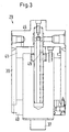
- the cylinders 26-29 have a special construction that will be explained with reference to FIGS. 2 and 3. Shown is the cylinder 29, the explanations accordingly apply to cylinders 26-28 because these are identical. 2 shows the cylinder 29 with extended piston rod 37, while Fig. 3 the cylinder 29 shows with the piston rod 37 retracted.
- the piston rod 37 is arranged on a piston 38, which is movable in a cylinder housing 39.
- the piston 38 penetrates a cover plate 40 of the cylinder housing 39 and is opposite the peripheral wall of the Cylinder housing guided with a face plate 41, the is fastened to the piston 38 by means of bolts 42.
- the Piston 38 has a central bore 43 which extends over almost the entire length of the piston 38 and is at least as long as the stroke H of the piston 38.
- a tube 44 protrudes into the bore 43, which is on the cylinder housing 39, more precisely on a base plate 45 is attached.
- the tube 44 has an end face Opening 46, which opens into the bore 43.
- the pipe 44 is surrounded by a seal 47 on the front End of the piston 38 so arranged in the bore 43 is that it bears sealingly against tube 44.
- the Face plate 41 surrounds the tube 44 with a predetermined Distance, so that between the end plate 41st and an annular space 48 is formed for the tube 44.
- the tube 44 has a plurality of openings in its wall 49 on that of one inside the tube trained channel 50 to the pressure chamber 51, when the piston 38 is extended.
- Channel 50 is connected to a drain port 52.
- the pressure room 51 has a further connection 53. Through this connection 53, for example, the pressure of the hydraulic fluid determine in the pressure chamber 51. It is but also possible here to close the Nips 19-23 supply hydraulic fluid. Further the cylinder housing 39 still has a leakage oil connection 54 on, through the hydraulic fluid that at a Sealing arrangement 55 of the end plate 41 penetrated is can be removed.
- the piston is in the position shown in FIG. 2 38 most extended. Accordingly, they are most of the openings 49 are free, i.e. over the openings 49 is the channel 50 and thus the drain connection 52nd with the pressure chamber 51 in connection. If now the pitch cylinder 6 is relieved and the lower roller 5 is lowered, then the middle rollers 7-10 are no longer the lower roller 5 is supported so that the entire weight the center roll 7-10 from the corresponding cylinder 26-29 must be caught. Accordingly increases the pressure in the pressure chamber 51. Via a not shown Control device is now enabled that hydraulic fluid flows through the drain port 52. The control device ensures that the pressure in the pressure chamber 51 does not drop, but if necessary even increases to a small extent.
- Fig. 4 shows two different alternatives. With circles it is Marked course, which results when the Openings 49 in the axial direction evenly over the length of the tube 44 are distributed. In this case achieved the piston relatively quickly reaches its maximum speed. This speed then drops until it is reached linearly from the end position at about 100 mm.
- a quadratic function distributed the length of the tube 44, i.e. in the farthest extended position of the piston 38 becomes a disproportionately large outflow area through the openings 49 released, which at the end of the stroke (Fig. 3) very much reduced. In this case, a longer driveway a higher speed reached.
- Fig. 5 shows the speed distribution over the Time. After about half a second is the maximum Falling speed of levers 11-14 reached. This then decreases almost linearly. The small gradations result by the fact that the openings 49 are not continuous reducing outflow area available but a gradual reduction.
- Fig. 6 shows the pressure conditions in the pressure chamber 51.
- the Pressure rises slightly.
- the spikes in the curve are due to the fact that when a Openings 49 through the seal 47 a short pressure surge he follows.
- All middle rollers 7-10 move with the maximum Speed, this speed too The beginning of the opening movement is greater than the end.
- the speed distribution is from below graded upwards so that the lower one The roller moves faster than the one above. In order to is a collision between adjacent rollers excluded when opening the nips 19-23.
Landscapes
- Paper (AREA)
- Casting Or Compression Moulding Of Plastics Or The Like (AREA)
Abstract
Description
- Fig. 1
- eine schematische Darstellung eines Kalanders,
- Fig. 2
- einen Zylinder mit ausgefahrenem Kolben,
- Fig. 3
- einen Zylinder mit eingefahrenem Kolben,
- Fig. 4
- zwei Kurven zur Abhängigkeit der Geschwindigkeit vom Weg,
- Fig. 5
- eine Kurve zur Darstellung der Abhängigkeit der Geschwindigkeit von der Zeit und
- Fig. 6
- eine Kurve zur Darstellung des Druckverlaufs über der Zeit.
Claims (15)
- Kalander mit einem Ständer, einer Oberwalze, einer Unterwalze und dazwischen mindestens zwei Mittelwalzen, die über Zylinder am Ständer abgestützt sind, dadurch gekennzeichnet, daß der Zylinder (26-29) einen über mehr als ¾ des zum Absenken der Mittelwalze benötigten Kolbenhubs gesteuerten Ausströmpfad aufweist.
- Kalander nach Anspruch 1, dadurch gekennzeichnet, daß der Ausströmpfad durch eine Bewegung des Kolbens (38) relativ zum Zylindergehäuse (39) gesteuert ist.
- Kalander nach Anspruch 1 oder 2, dadurch gekennzeichnet, daß der Widerstand des Ausströmpfades zunimmt, je weiter der Kolben (38) in das Zylindergehäuse (39) eingefahren ist.
- Kalander nach einem der Ansprüche 1 bis 3, dadurch gekennzeichnet, daß die Zylinder (26-29) unterschiedlicher Mittelwalzen (7-10) bei geschlossenen Nips (19-23) unterschiedliche Widerstände der Ausströmpfade aufweisen, wobei die Widerstände von unten nach oben zunehmen.
- Kalander nach Anspruch 4, dadurch gekennzeichnet, daß die Zylinder (26-29) zueinander gleich ausgebildet, bei geschlossenen Nips (19-23) aber unterschiedlich weit ausgefahrene Kolben (38) aufweisen.
- Kalander nach einem der Ansprüche 1 bis 5, dadurch gekennzeichnet, daß im Zylindergehäuse (39) ein Rohr (44) angeordnet ist, das Öffnungen (49) in seiner Wand aufweist und in eine Bohrung (43) im Kolben (38) hineinragt.
- Kalander nach Anspruch 6, dadurch gekennzeichnet, daß das Rohr (44) über den gesamten Kolbenhub (H) in den Kolben (38) hineinragt.
- Kalander nach Anspruch 6 oder 7, dadurch gekennzeichnet, daß zwischen Kolben (38) und Rohr (44) eine Dichtung (47) angeordnet ist.
- Kalander nach einem der Ansprüche 6 bis 8, dadurch gekennzeichnet, daß das Rohr (44) stirnseitig offen ist.
- Kalander nach einem der Ansprüche 6 bis 9, dadurch gekennzeichnet, daß das Rohr (44) zentrisch im Zylindergehäuse (39) und zentrisch zum Kolben (38) angeordnet ist.
- Kalander nach einem der Ansprüche 6 bis 10, dadurch gekennzeichnet, daß die Öffnungen (49) über die Länge des Rohres (44) gleichmäßig verteilt sind.
- Kalander nach einem der Ansprüche 6 bis 10, dadurch gekennzeichnet, daß die Öffnungen (49) nach einer vorbestimmten nichtlinearen Funktion über die Länge des Rohres (44) verteilt sind, bei der der Ausströmquerschnitt zum Ende der Hubbewegung überproportional abnimmt.
- Kalander nach Anspruch 12, dadurch gekennzeichnet, daß die Funktion eine quadratische Funktion ist.
- Kalander nach einem der Ansprüche 1 bis 13, dadurch gekennzeichnet, daß der Ausströmpfad mit einer Steuereinrichtung verbunden, die ein Absinken des Drucks im Zylindergehäuse (39) verhindert.
- Kalander nach Anspruch 14, dadurch gekennzeichnet, daß die Steuereinrichtung den Druck im Zylinder (39) beim Einfahren des Kolbens (38) geringfügig erhöht.
Applications Claiming Priority (2)
| Application Number | Priority Date | Filing Date | Title |
|---|---|---|---|
| DE10010772 | 2000-03-04 | ||
| DE10010772A DE10010772C1 (de) | 2000-03-04 | 2000-03-04 | Kalander |
Publications (3)
| Publication Number | Publication Date |
|---|---|
| EP1130160A2 true EP1130160A2 (de) | 2001-09-05 |
| EP1130160A3 EP1130160A3 (de) | 2002-01-16 |
| EP1130160B1 EP1130160B1 (de) | 2004-04-28 |
Family
ID=7633628
Family Applications (1)
| Application Number | Title | Priority Date | Filing Date |
|---|---|---|---|
| EP01104008A Expired - Lifetime EP1130160B1 (de) | 2000-03-04 | 2001-02-20 | Kalander |
Country Status (3)
| Country | Link |
|---|---|
| US (1) | US6606940B2 (de) |
| EP (1) | EP1130160B1 (de) |
| DE (2) | DE10010772C1 (de) |
Families Citing this family (3)
| Publication number | Priority date | Publication date | Assignee | Title |
|---|---|---|---|---|
| DE10206256B4 (de) * | 2002-02-15 | 2006-09-21 | Beiersdorf Ag | Flächenkalandar und Flächenkalandrierverfahren |
| FI5496U1 (fi) * | 2002-06-10 | 2002-08-28 | Metso Paper Inc | Moninippikalanterin kevennyssylinterirakenne |
| FI121082B (fi) * | 2006-10-06 | 2010-06-30 | Metso Paper Inc | Menetelmä ja järjestely telaston pika-avaamiseksi monitelakalenterissa |
Family Cites Families (6)
| Publication number | Priority date | Publication date | Assignee | Title |
|---|---|---|---|---|
| GB1291086A (en) * | 1968-11-27 | 1972-09-27 | Kleinewefers Soehne J | Means for setting a roll gap |
| DE3640161A1 (de) * | 1985-12-23 | 1987-07-02 | Escher Wyss Gmbh | Vorrichtung zum zueinander positionieren von walzenflaechen |
| DE3702245C3 (de) | 1987-01-27 | 1993-12-23 | Kleinewefers Gmbh | Kalander |
| FI83346C (fi) * | 1989-01-27 | 1991-06-25 | Valmet Paper Machinery Inc | Kalander, saerskilt en superkalander. |
| DE4314670C2 (de) * | 1993-05-04 | 1996-02-01 | Kleinewefers Gmbh | Kalander |
| FI107626B (fi) * | 1996-05-06 | 2001-09-14 | Metso Paper Inc | Menetelmä kalanterin, etenkin superkalanterin telaston pika-avauksessa ja hydraulijärjestelmä kalanterin, etenkin superkalanterin telastoa varten |
-
2000
- 2000-03-04 DE DE10010772A patent/DE10010772C1/de not_active Expired - Fee Related
-
2001
- 2001-02-20 DE DE50102094T patent/DE50102094D1/de not_active Expired - Lifetime
- 2001-02-20 EP EP01104008A patent/EP1130160B1/de not_active Expired - Lifetime
- 2001-03-02 US US09/796,453 patent/US6606940B2/en not_active Expired - Fee Related
Also Published As
| Publication number | Publication date |
|---|---|
| DE10010772C1 (de) | 2001-05-10 |
| US20010018869A1 (en) | 2001-09-06 |
| EP1130160B1 (de) | 2004-04-28 |
| US6606940B2 (en) | 2003-08-19 |
| DE50102094D1 (de) | 2004-06-03 |
| EP1130160A3 (de) | 2002-01-16 |
Similar Documents
| Publication | Publication Date | Title |
|---|---|---|
| DE3820974C2 (de) | ||
| DE3640161C2 (de) | ||
| EP0273185B1 (de) | Walze mit steuerbarem Liniendruck | |
| EP2580507B1 (de) | Ventilanordnung | |
| DE2623492C3 (de) | Vorrichtung zur Drucksteuerung für Walzeinrichtungen | |
| DE2410077A1 (de) | Einrichtung zur einstellung des durchflussquerschnittes bei hydraulischen ventilen | |
| EP2529137B1 (de) | Druckbegrenzungsventil | |
| DE102004030045B3 (de) | Ventilanordnung in einem Hydraulikkreis, Verwendung derselben und Anordnung zum Steuern eines hydraulischen Fahrzeugantriebs | |
| WO2005011885A1 (de) | Walzvorrichtung | |
| DE2320363B2 (de) | Kalander | |
| CH680151A5 (de) | ||
| EP1130160B1 (de) | Kalander | |
| EP0505349B2 (de) | Hydraulische Zylinder/Kolben-Anordnung | |
| WO2005011884A1 (de) | Walzvorrichtung | |
| DE3805323C1 (de) | ||
| DE2748611C2 (de) | ||
| DE19608801A1 (de) | Hydraulisches Lasthalte- bzw. Senkbremsventil | |
| EP1176252B1 (de) | Kalander | |
| DE3100093C2 (de) | ||
| CH649484A5 (de) | Vertikal-druckgiessmaschine mit einem rueckzugszylinderaggregat. | |
| DE2558068C2 (de) | Hydrostatische Stützvorrichtung | |
| DE2010322C3 (de) | Vorrichtung zum Belasten und Trennen der Walzen eines Kalanders | |
| DE1773415C3 (de) | Druckregelventil fur hydraulische Flüssigkeiten | |
| EP0918946B1 (de) | Kalander | |
| DE2915505A1 (de) | Kraftbegrenzer fuer eine stellstange |
Legal Events
| Date | Code | Title | Description |
|---|---|---|---|
| PUAI | Public reference made under article 153(3) epc to a published international application that has entered the european phase |
Free format text: ORIGINAL CODE: 0009012 |
|
| AK | Designated contracting states |
Kind code of ref document: A2 Designated state(s): DE FI FR GB SE Kind code of ref document: A2 Designated state(s): AT BE CH CY DE DK ES FI FR GB GR IE IT LI LU MC NL PT SE TR |
|
| AX | Request for extension of the european patent |
Free format text: AL;LT;LV;MK;RO;SI |
|
| PUAL | Search report despatched |
Free format text: ORIGINAL CODE: 0009013 |
|
| AK | Designated contracting states |
Kind code of ref document: A3 Designated state(s): AT BE CH CY DE DK ES FI FR GB GR IE IT LI LU MC NL PT SE TR |
|
| AX | Request for extension of the european patent |
Free format text: AL;LT;LV;MK;RO;SI |
|
| 17P | Request for examination filed |
Effective date: 20011219 |
|
| AKX | Designation fees paid |
Free format text: DE FI FR GB SE |
|
| GRAP | Despatch of communication of intention to grant a patent |
Free format text: ORIGINAL CODE: EPIDOSNIGR1 |
|
| GRAS | Grant fee paid |
Free format text: ORIGINAL CODE: EPIDOSNIGR3 |
|
| GRAA | (expected) grant |
Free format text: ORIGINAL CODE: 0009210 |
|
| AK | Designated contracting states |
Kind code of ref document: B1 Designated state(s): DE FI FR GB SE |
|
| REG | Reference to a national code |
Ref country code: GB Ref legal event code: FG4D Free format text: NOT ENGLISH |
|
| REG | Reference to a national code |
Ref country code: IE Ref legal event code: FG4D Free format text: GERMAN |
|
| REF | Corresponds to: |
Ref document number: 50102094 Country of ref document: DE Date of ref document: 20040603 Kind code of ref document: P |
|
| REG | Reference to a national code |
Ref country code: SE Ref legal event code: TRGR |
|
| GBT | Gb: translation of ep patent filed (gb section 77(6)(a)/1977) |
Effective date: 20040806 |
|
| REG | Reference to a national code |
Ref country code: IE Ref legal event code: FD4D |
|
| ET | Fr: translation filed | ||
| PLBE | No opposition filed within time limit |
Free format text: ORIGINAL CODE: 0009261 |
|
| STAA | Information on the status of an ep patent application or granted ep patent |
Free format text: STATUS: NO OPPOSITION FILED WITHIN TIME LIMIT |
|
| 26N | No opposition filed |
Effective date: 20050131 |
|
| PGFP | Annual fee paid to national office [announced via postgrant information from national office to epo] |
Ref country code: SE Payment date: 20060214 Year of fee payment: 6 |
|
| PGFP | Annual fee paid to national office [announced via postgrant information from national office to epo] |
Ref country code: FR Payment date: 20060216 Year of fee payment: 6 |
|
| PG25 | Lapsed in a contracting state [announced via postgrant information from national office to epo] |
Ref country code: SE Free format text: LAPSE BECAUSE OF NON-PAYMENT OF DUE FEES Effective date: 20070221 |
|
| EUG | Se: european patent has lapsed | ||
| GBPC | Gb: european patent ceased through non-payment of renewal fee |
Effective date: 20070220 |
|
| REG | Reference to a national code |
Ref country code: FR Ref legal event code: ST Effective date: 20071030 |
|
| PG25 | Lapsed in a contracting state [announced via postgrant information from national office to epo] |
Ref country code: FR Free format text: LAPSE BECAUSE OF NON-PAYMENT OF DUE FEES Effective date: 20070228 Ref country code: GB Free format text: LAPSE BECAUSE OF NON-PAYMENT OF DUE FEES Effective date: 20070220 |
|
| PGFP | Annual fee paid to national office [announced via postgrant information from national office to epo] |
Ref country code: GB Payment date: 20060221 Year of fee payment: 6 |
|
| PGFP | Annual fee paid to national office [announced via postgrant information from national office to epo] |
Ref country code: FI Payment date: 20150211 Year of fee payment: 15 Ref country code: DE Payment date: 20150219 Year of fee payment: 15 |
|
| REG | Reference to a national code |
Ref country code: DE Ref legal event code: R119 Ref document number: 50102094 Country of ref document: DE |
|
| PG25 | Lapsed in a contracting state [announced via postgrant information from national office to epo] |
Ref country code: FI Free format text: LAPSE BECAUSE OF NON-PAYMENT OF DUE FEES Effective date: 20160220 |
|
| PG25 | Lapsed in a contracting state [announced via postgrant information from national office to epo] |
Ref country code: DE Free format text: LAPSE BECAUSE OF NON-PAYMENT OF DUE FEES Effective date: 20160901 |