EP1129634B1 - Verschluss für Fussbekleidung - Google Patents
Verschluss für Fussbekleidung Download PDFInfo
- Publication number
- EP1129634B1 EP1129634B1 EP01301606A EP01301606A EP1129634B1 EP 1129634 B1 EP1129634 B1 EP 1129634B1 EP 01301606 A EP01301606 A EP 01301606A EP 01301606 A EP01301606 A EP 01301606A EP 1129634 B1 EP1129634 B1 EP 1129634B1
- Authority
- EP
- European Patent Office
- Prior art keywords
- fastener
- devices
- strap
- magnet
- operable
- Prior art date
- Legal status (The legal status is an assumption and is not a legal conclusion. Google has not performed a legal analysis and makes no representation as to the accuracy of the status listed.)
- Expired - Lifetime
Links
Images

Classifications
-
- A—HUMAN NECESSITIES
- A43—FOOTWEAR
- A43C—FASTENINGS OR ATTACHMENTS OF FOOTWEAR; LACES IN GENERAL
- A43C11/00—Other fastenings specially adapted for shoes
- A43C11/14—Clamp fastenings, e.g. strap fastenings; Clamp-buckle fastenings; Fastenings with toggle levers
-
- A—HUMAN NECESSITIES
- A43—FOOTWEAR
- A43B—CHARACTERISTIC FEATURES OF FOOTWEAR; PARTS OF FOOTWEAR
- A43B1/00—Footwear characterised by the material
- A43B1/0054—Footwear characterised by the material provided with magnets, magnetic parts or magnetic substances
-
- Y—GENERAL TAGGING OF NEW TECHNOLOGICAL DEVELOPMENTS; GENERAL TAGGING OF CROSS-SECTIONAL TECHNOLOGIES SPANNING OVER SEVERAL SECTIONS OF THE IPC; TECHNICAL SUBJECTS COVERED BY FORMER USPC CROSS-REFERENCE ART COLLECTIONS [XRACs] AND DIGESTS
- Y10—TECHNICAL SUBJECTS COVERED BY FORMER USPC
- Y10T—TECHNICAL SUBJECTS COVERED BY FORMER US CLASSIFICATION
- Y10T24/00—Buckles, buttons, clasps, etc.
- Y10T24/32—Buckles, buttons, clasps, etc. having magnetic fastener
Definitions
- the present invention relates to a fastener for footwear and in particular to a fastener suitable for all types and designs of footwear that employ straps for securement especially but not exclusively sandals.
- footwear such as sandals have two or three separate straps each carrying a fastener. This enables the sandal to be securely fastened to the foot when worn but also makes the sandal easy to remove.
- the fastener for such sandal straps is most commonly in the form of a buckle that allows for adjustment of the length of the strap for comfort. More recently alternative fasteners such as Velcro TM have been used.
- German publication DE 197 19 269 describes a magnetic fastener for shoes, bags, rucksacks and the like.
- This fastener consists of two co-operating magnets: one recessed within its mount and the other protruding from a second mount by an equivalent extent. In this way, when fastened, the first mount contains the protrusion of the second magnet and relative shear movement of the two parts of the fastener is prevented.
- the present invention seeks to provide a new fastener for footwear that is simple and easy to operate.
- the present invention provides a fastener for use on footwear comprising first and second inter-engaging devices at least one of the devices having a magnetically attractive member for holding the two devices together, the first and second inter-engaging devices further including co-operable surfaces for preventing shear movement of the devices relative to one another.
- the first device further includes strap attachment means for securing a strap to the first device.
- the fastener is characterised in that the co-operable surface of the first device and the strap attachment means are located at opposite ends of the first device such that when the two devices are held together the co-operable surfaces of the first and second devices prevent relative shear movement other than as follows: the shear movement of the second device in a direction of the strap secured to the strap attachment means of the first device is permitted.
- the first device further includes handle means for enabling the device to be gripped.
- the second device may further include securement means for enabling securement of the second device to a surface in which the securement means may comprise a pair of flanges.
- the magnetically attractive members of the first and second devices consist of a pair of cylindrical magnets and the co-operable surfaces of the first and second devices may comprise the outer surface of a curved wall and a follower.
- the fastener 1 consists of two inter-engaging devices: a clasp 2 and a lug member 3.
- the clasp 2 is shown and consists of a main body 4 with an outwardly extending grip 5, strap engaging means 6 for securing the clasp 2 to a strap 7, a downwardly depending tooth 8 and a first magnet 9.
- the main body 4 is preferably moulded from hard plastic such as nylon or acetal and includes a downwardly facing recess 10 in which the magnet is located.
- the strap engaging means 6 illustrated in Figure 1 is a bar arranged to pass through a loop provided in the end of the strap 7, any suitable strap securement mechanism may be used.
- the magnet 9 is generally cylindrical and is located between the strap engaging means 6 and the tooth 8.
- the downwardly depending tooth 8 is located at the opposite end of the main body to the strap engaging means 6 and is preferably integrally moulded with the main body 4.
- the tooth 8 projects beyond the exposed surface of the magnet and describes an arc that substantially corresponds to, but lies outside of, the perimeter of the first magnet 9.
- the tooth 8 need not comprise a single downwardly depending flange and instead may be constructed from a plurality of smaller spaced fingers.
- the grip 5 extends away from the tooth 8 and the main body 4 and provides a ledge that is grasped by someone wishing to release the fastener, as is described in greater detail below.
- the grip 5 may be made moulded with the main body 4 in a hard plastics material or may be made from a softer plastics material to improve the ease of use of the grip and enhance its tactile value. In the latter case, the grip may be moulded to the main body in a two-shot moulding process. The surface of the grip 5 may be contoured or roughened to further improve its tactile value.
- the lug 3 is i lustrated in Figure 2 and comprises a base support 11 on which is secured a second magnet 12.
- the second magnet 12 is also generally cylindrical and is surrounded by a perimeter wall 13 to further hold the magnet 12 in place.
- flanges 14 are provided to enable the lug to be secured to a strap or upper.
- the base support 11 of the lug 3 is preferably moulded from hard plastics material and ideally the same material as the clasp, the flanges 14 are best moulded so as to be thinner than the rest of the fastener. This enables the flanges 14 to be stitched to a strap or upper.
- the lug may be attached to a strap or upper by means of a suitable adhesive.
- the first and second magnets 9,12 are of conventional ferric material or a more specialised magnetic compound such as bonded neodemium may be used. Both are coated, for example with a plated nickel finish, to protect the magnets from corrosion.
- the magnets 9,12 are bonded or moulded in to the clasp 2 and lug 3 with the exposed surface of each magnet being approximately flush with the edges of the surrounding walls of either the main body 4 or the perimeter wall 13. In this way dirt can be prevented from becoming trapped in between the magnets and the mouldings in which they are mounted and can prevent dirt from partially obscuring the surface of the magnets.
- each magnet has a large exposed face for contact with the face of the opposing magnet.
- both magnetic members may be permanently magnetised, in an alternative embodiment only one of the magnetic members is permanently magnetised and the second of the magnetic members is constructed from a material that is attracted to the opposing magnetic member.
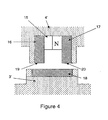
- Figure 4 an alternative fastener is shown which employs a single magnet. With this arrangement the magnet 15 is mounted in the main body 4' with opposing metal bands 16,17 either side of the magnet 15. In the lug 3' a metal plate 18 is provided that extends so as to engage with end faces 19,20 of the metal bands.
- the metal bands 16,17 and the plate 18 may be made from steel, for example.
- Such an arrangement has an advantage over two magnet arrangements of lower material costs as well as concealment and protection for the magnet.
- the fastener may have only one lug and so be restricted in its fastening position, it possible for a plurality of lugs to be provided on a strap or the upper in a line to allow for different fastening positions. Adjustments to the structure and arrangement of the parts of the fastener are envisaged without departing from the scope of the present invention, as defined by the appended claims
Landscapes
- Footwear And Its Accessory, Manufacturing Method And Apparatuses (AREA)
- Purses, Travelling Bags, Baskets, Or Suitcases (AREA)
- Buckles (AREA)
Claims (9)
- Verschluss zur Verwendung auf Fußbekleidung, umfassend eine erste (2) und eine zweite (3) Vorrichtung, die ineinander greifen, wobei jede der ineinandergreifenden Vorrichtungen jeweilige Halteelemente (9, 12) aufweist, um die zwei Vorrichtungen zusammenzuhalten, wobei mindestens eines der Halteelemente (9, 12) magnetisch anziehend ist und die erste (2) und die zweite (3) ineinandergreifende Vorrichtung Oberflächen (8, 13) einschließen, die zusammenwirken können, um eine Scherbewegung der Vorrichtungen relativ zueinander zu verhindern, wobei die erste Vorrichtung (2) weiter Riemenbefestigungsmittel (6) zur Befestigung eines Riemens (7) an der ersten Vorrichtung einschließt, dadurch gekennzeichnet, dass die Oberfläche (8) der ersten Vorrichtung, die zusammenwirken kann, und die Riemenbefestigungsmittel (6) zu entgegengesetzten Enden der ersten Vorrichtung hin angeordnet sind, so dass, wenn die zwei Vorrichtungen (2, 3) zusammengehalten werden, die Oberflächen (8, 13) der ersten und der zweiten Vorrichtung, die zusammenwirken können, eine andere relative Scherbewegung als die relative Scherbewegung der zweiten Vorrichtung in Richtung des an den Riemenbefestigungsmitteln (6) der ersten Vorrichtung befestigten Riemens (7) verhindern.
- Verschluss nach Anspruch 1, bei dem die Oberflächen (8, 13) der ersten und der zweiten Vorrichtung, die zusammenwirken können, ein Paar Wände umfassen, wobei die erste Wand (8) des Paars eine Innenseite aufweist, die einen Bogen beschreibt, und die zweite Wand (13) des Paars eine Außenseite aufweist, die der Innenseite der ersten Wand im Wesentlichen entspricht.
- Verschluss nach Anspruch 2, bei dem eine von der ersten (8) oder der zweiten (13) Wand von einer Mehrzahl von im Abstand angeordneten Fingern beschrieben wird, die angeordnet sind, um einen Bogen zu bilden.
- Verschluss nach einem der vorangehenden Ansprüche, bei dem die erste Vorrichtung (2) weiter Griffmittel (5) einschließt, um es zu ermöglichen, die Vorrichtung zu ergreifen.
- Verschluss nach einem der vorangehenden Ansprüche, bei dem die zweite Vorrichtung (3) weiter Befestigungsmittel (14) einschließt, um eine Befestigung der zweiten Vorrichtung an einer Oberfläche zu ermöglichen.
- Verschluss nach einem der vorangehenden Ansprüche, bei dem die erste Vorrichtung (2) das magnetisch anziehende Halteelement (9, 15) einschließt, das zwischen der Oberfläche (8), die zusammenwirken kann, und den Riemenbefestigungsmitteln (6) angeordnet ist.
- Verschluss nach Anspruch 6, bei dem das magnetisch anziehende Halteelement (9) der ersten Vorrichtung einen Magneten (15) umfasst, der gegenüberliegende Metallstreifen (16, 17) beiderseits des Magneten umfasst, und das Halteelement der zweiten Vorrichtung eine Metallplatte (18) umfasst, die mit den Stirnflächen der Metallstreifen in Eingriff tritt, wenn die zwei Vorrichtungen zusammengehalten werden.
- Verschluss nach einem der Ansprüche 1 bis 6, bei dem die Halteelemente (9, 12) der ersten und der zweiten Vorrichtung aus jeweiligen magnetisch anziehenden Elementen in Form eines Paars von zylindrischen Magneten bestehen.
- Verschluss nach einem der vorangehenden Ansprüche, bei dem die erste (2) und die zweite (3) Vorrichtung aus geformtem Kunststoff hergestellt sind.
Applications Claiming Priority (2)
| Application Number | Priority Date | Filing Date | Title |
|---|---|---|---|
| GBGB0004821.5A GB0004821D0 (en) | 2000-02-29 | 2000-02-29 | Fastener for footwear |
| GB0004821 | 2000-02-29 |
Publications (2)
| Publication Number | Publication Date |
|---|---|
| EP1129634A1 EP1129634A1 (de) | 2001-09-05 |
| EP1129634B1 true EP1129634B1 (de) | 2006-08-23 |
Family
ID=9886654
Family Applications (1)
| Application Number | Title | Priority Date | Filing Date |
|---|---|---|---|
| EP01301606A Expired - Lifetime EP1129634B1 (de) | 2000-02-29 | 2001-02-22 | Verschluss für Fussbekleidung |
Country Status (6)
| Country | Link |
|---|---|
| US (1) | US6532687B2 (de) |
| EP (1) | EP1129634B1 (de) |
| AT (1) | ATE336917T1 (de) |
| DE (1) | DE60122404T2 (de) |
| ES (1) | ES2270960T3 (de) |
| GB (1) | GB0004821D0 (de) |
Cited By (1)
| Publication number | Priority date | Publication date | Assignee | Title |
|---|---|---|---|---|
| DE102011012159A1 (de) | 2010-05-14 | 2011-11-17 | Max Neumeyer | Verschluss für Fußbekleidung |
Families Citing this family (12)
| Publication number | Priority date | Publication date | Assignee | Title |
|---|---|---|---|---|
| US6880270B2 (en) * | 2001-07-13 | 2005-04-19 | Suzanne K. Prather | Shoe with magnetic fastener |
| US6829847B2 (en) * | 2002-09-12 | 2004-12-14 | Global Brand Marketing Inc. | Pant cuff protector |
| US7444768B2 (en) * | 2004-02-12 | 2008-11-04 | Nike, Inc. | Footwear and other systems including a flexible mesh or braided closure system |
| US7650704B2 (en) * | 2006-04-12 | 2010-01-26 | Richardson Margaret A | Footwear system with interchangeable portions |
| KR100833682B1 (ko) * | 2006-04-27 | 2008-05-29 | 황종오 | 신발끈의 결속장치 |
| FR2905605B1 (fr) * | 2006-09-13 | 2008-11-21 | Salomon Sa | Article comprenant un lien de retenue ou de serrage d'un pied ou d'une chaussure. |
| US8282667B2 (en) | 2009-06-05 | 2012-10-09 | Entellus Medical, Inc. | Sinus dilation catheter |
| WO2012027311A2 (en) | 2010-08-26 | 2012-03-01 | Linda Faye Moore | Two-piece transformable boot |
| EP2948015B1 (de) | 2013-01-28 | 2018-05-16 | Fox Head, Inc. | Befestigungssystem für schuhe |
| USD769608S1 (en) | 2014-12-12 | 2016-10-25 | Zubits, Llc | Footwear closure |
| US9730494B1 (en) | 2016-09-23 | 2017-08-15 | Feinstein Patents, Llc | Self-fitting, self-adjusting, automatically adjusting and/or automatically fitting shoe/sneaker/footwear |
| US10674779B2 (en) * | 2017-08-30 | 2020-06-09 | Nike, Inc. | Magnetic fastener for an article of footwear |
Family Cites Families (15)
| Publication number | Priority date | Publication date | Assignee | Title |
|---|---|---|---|---|
| CH374845A (de) * | 1959-11-10 | 1964-01-31 | Matzinger Walter Dr Med | Knopf zum Verbinden von textilen Flächengebilden, z. B. Kleidungs- und Wäschestücken |
| DE1168140B (de) * | 1961-03-13 | 1964-04-16 | Kangol Helmets Ltd | Verschlussschnalle fuer Sicherheitsgurt |
| US3111737A (en) * | 1962-04-02 | 1963-11-26 | North & Judd Mfg Co | Magnetic fastener |
| US3324521A (en) | 1966-03-18 | 1967-06-13 | Scovill Manufacturing Co | Magnetic fastening means |
| DE2434177A1 (de) * | 1974-07-16 | 1976-02-05 | Ludwig Bourguignon | Halte- und verschlusselement fuer nichtmagnetische artikel |
| JPS557938U (de) * | 1978-06-29 | 1980-01-19 | ||
| US4249267A (en) | 1979-09-04 | 1981-02-10 | Voss Clifford C | Magnetic fabric fastener and closure means |
| DE3306396A1 (de) * | 1983-02-24 | 1984-08-30 | Birkenstock Orthopädie GmbH, 5340 Bad Honnef | Verschluss fuer schuhwerk |
| US4646350A (en) * | 1984-03-23 | 1987-02-24 | Batra Vijay K | Shoe with audible message |
| JPS6035502A (ja) * | 1984-04-27 | 1985-02-23 | Tamao Morita | バンド係合具 |
| US5432986A (en) | 1993-06-15 | 1995-07-18 | Sexton; Jason | Magnetic fastener |
| US5473799A (en) | 1994-02-23 | 1995-12-12 | Application Art Laboratories Co., Ltd. | Magnetic closure device |
| DE19719269C2 (de) * | 1996-09-27 | 2001-05-31 | Inga Bauer | Magnetverschluß |
| DE19729610A1 (de) * | 1997-07-10 | 1999-01-14 | Weber Unger Georg | Verschluß für Bekleidungsstücke |
| IT1297007B1 (it) * | 1997-12-22 | 1999-08-03 | Sama S P A | Chiusura magnetica ad innesto reciproco per borse, zaini, capi di abbigliamento e simili |
-
2000
- 2000-02-29 GB GBGB0004821.5A patent/GB0004821D0/en not_active Ceased
-
2001
- 2001-02-22 AT AT01301606T patent/ATE336917T1/de not_active IP Right Cessation
- 2001-02-22 EP EP01301606A patent/EP1129634B1/de not_active Expired - Lifetime
- 2001-02-22 DE DE60122404T patent/DE60122404T2/de not_active Expired - Lifetime
- 2001-02-22 ES ES01301606T patent/ES2270960T3/es not_active Expired - Lifetime
- 2001-02-23 US US09/792,822 patent/US6532687B2/en not_active Expired - Lifetime
Cited By (1)
| Publication number | Priority date | Publication date | Assignee | Title |
|---|---|---|---|---|
| DE102011012159A1 (de) | 2010-05-14 | 2011-11-17 | Max Neumeyer | Verschluss für Fußbekleidung |
Also Published As
| Publication number | Publication date |
|---|---|
| EP1129634A1 (de) | 2001-09-05 |
| US20020078596A1 (en) | 2002-06-27 |
| GB0004821D0 (en) | 2000-04-19 |
| DE60122404D1 (de) | 2006-10-05 |
| ATE336917T1 (de) | 2006-09-15 |
| DE60122404T2 (de) | 2007-05-03 |
| US6532687B2 (en) | 2003-03-18 |
| ES2270960T3 (es) | 2007-04-16 |
Similar Documents
| Publication | Publication Date | Title |
|---|---|---|
| EP1129634B1 (de) | Verschluss für Fussbekleidung | |
| US8978213B2 (en) | Clamping buckle for belts and straps | |
| US20060163295A1 (en) | Belt clip | |
| EP3641582B1 (de) | Magnethaken | |
| US4942663A (en) | Sheath | |
| US20040232180A1 (en) | Belt clip and locking fastener for selectively securing an electronic device | |
| WO2020214232A1 (en) | A detachable finger grip for a mobile electronic device | |
| GB2355281A (en) | Magnetic fastener | |
| US7284304B2 (en) | Retaining assembly | |
| KR100548955B1 (ko) | 키를 갖는 파스너 | |
| US20050035164A1 (en) | Belt clip and locking fastener for selectively securing an electronic device | |
| EP1319348A2 (de) | Wechselbare selbeinstellende Vorrichtung für Gürtel | |
| US20190160930A1 (en) | Hand-held magnetic clamping device for car covers | |
| US20080041899A1 (en) | Personal Accessory Carrier | |
| JP2019201994A (ja) | 衣服ベルト用バックル | |
| WO2003047819A1 (en) | Armband for holding fastening pieces | |
| USD411478S (en) | Magnetic aligning spring snap fastener | |
| US5170541A (en) | Fastening apparatus for handbag straps | |
| KR101633418B1 (ko) | 간편하게 이중 구조로 체결되는 손목 시계줄 체결구조 | |
| WO2006002428A9 (en) | Two-position fastener for brassieres | |
| USD439147S1 (en) | Magnetic aligning spring snap fastener | |
| JPS6239056Y2 (de) | ||
| US11116305B2 (en) | Appliance belt clip and holster system | |
| US20200336580A1 (en) | Detachable finger grip for a mobile electronic device | |
| WO2024026421A1 (en) | Backpack or shoulder strap accessory mount |
Legal Events
| Date | Code | Title | Description |
|---|---|---|---|
| PUAI | Public reference made under article 153(3) epc to a published international application that has entered the european phase |
Free format text: ORIGINAL CODE: 0009012 |
|
| AK | Designated contracting states |
Kind code of ref document: A1 Designated state(s): AT BE CH CY DE DK ES FI FR GB GR IE IT LI LU MC NL PT SE TR |
|
| AX | Request for extension of the european patent |
Free format text: AL;LT;LV;MK;RO;SI |
|
| 17P | Request for examination filed |
Effective date: 20020304 |
|
| AKX | Designation fees paid |
Free format text: AT BE CH CY DE DK ES FI FR GB GR IE IT LI LU MC NL PT SE TR |
|
| 17Q | First examination report despatched |
Effective date: 20040701 |
|
| GRAP | Despatch of communication of intention to grant a patent |
Free format text: ORIGINAL CODE: EPIDOSNIGR1 |
|
| GRAS | Grant fee paid |
Free format text: ORIGINAL CODE: EPIDOSNIGR3 |
|
| GRAA | (expected) grant |
Free format text: ORIGINAL CODE: 0009210 |
|
| AK | Designated contracting states |
Kind code of ref document: B1 Designated state(s): AT BE CH CY DE DK ES FI FR GB GR IE IT LI LU MC NL PT SE TR |
|
| PG25 | Lapsed in a contracting state [announced via postgrant information from national office to epo] |
Ref country code: IT Free format text: LAPSE BECAUSE OF FAILURE TO SUBMIT A TRANSLATION OF THE DESCRIPTION OR TO PAY THE FEE WITHIN THE PRESCRIBED TIME-LIMIT;WARNING: LAPSES OF ITALIAN PATENTS WITH EFFECTIVE DATE BEFORE 2007 MAY HAVE OCCURRED AT ANY TIME BEFORE 2007. THE CORRECT EFFECTIVE DATE MAY BE DIFFERENT FROM THE ONE RECORDED. Effective date: 20060823 Ref country code: FI Free format text: LAPSE BECAUSE OF FAILURE TO SUBMIT A TRANSLATION OF THE DESCRIPTION OR TO PAY THE FEE WITHIN THE PRESCRIBED TIME-LIMIT Effective date: 20060823 Ref country code: CH Free format text: LAPSE BECAUSE OF FAILURE TO SUBMIT A TRANSLATION OF THE DESCRIPTION OR TO PAY THE FEE WITHIN THE PRESCRIBED TIME-LIMIT Effective date: 20060823 Ref country code: LI Free format text: LAPSE BECAUSE OF FAILURE TO SUBMIT A TRANSLATION OF THE DESCRIPTION OR TO PAY THE FEE WITHIN THE PRESCRIBED TIME-LIMIT Effective date: 20060823 Ref country code: NL Free format text: LAPSE BECAUSE OF FAILURE TO SUBMIT A TRANSLATION OF THE DESCRIPTION OR TO PAY THE FEE WITHIN THE PRESCRIBED TIME-LIMIT Effective date: 20060823 Ref country code: BE Free format text: LAPSE BECAUSE OF FAILURE TO SUBMIT A TRANSLATION OF THE DESCRIPTION OR TO PAY THE FEE WITHIN THE PRESCRIBED TIME-LIMIT Effective date: 20060823 Ref country code: AT Free format text: LAPSE BECAUSE OF FAILURE TO SUBMIT A TRANSLATION OF THE DESCRIPTION OR TO PAY THE FEE WITHIN THE PRESCRIBED TIME-LIMIT Effective date: 20060823 |
|
| REG | Reference to a national code |
Ref country code: GB Ref legal event code: FG4D |
|
| REG | Reference to a national code |
Ref country code: CH Ref legal event code: EP |
|
| REG | Reference to a national code |
Ref country code: IE Ref legal event code: FG4D |
|
| REF | Corresponds to: |
Ref document number: 60122404 Country of ref document: DE Date of ref document: 20061005 Kind code of ref document: P |
|
| PG25 | Lapsed in a contracting state [announced via postgrant information from national office to epo] |
Ref country code: DK Free format text: LAPSE BECAUSE OF FAILURE TO SUBMIT A TRANSLATION OF THE DESCRIPTION OR TO PAY THE FEE WITHIN THE PRESCRIBED TIME-LIMIT Effective date: 20061123 Ref country code: SE Free format text: LAPSE BECAUSE OF FAILURE TO SUBMIT A TRANSLATION OF THE DESCRIPTION OR TO PAY THE FEE WITHIN THE PRESCRIBED TIME-LIMIT Effective date: 20061123 |
|
| PG25 | Lapsed in a contracting state [announced via postgrant information from national office to epo] |
Ref country code: PT Free format text: LAPSE BECAUSE OF FAILURE TO SUBMIT A TRANSLATION OF THE DESCRIPTION OR TO PAY THE FEE WITHIN THE PRESCRIBED TIME-LIMIT Effective date: 20070124 |
|
| NLV1 | Nl: lapsed or annulled due to failure to fulfill the requirements of art. 29p and 29m of the patents act | ||
| PG25 | Lapsed in a contracting state [announced via postgrant information from national office to epo] |
Ref country code: MC Free format text: LAPSE BECAUSE OF NON-PAYMENT OF DUE FEES Effective date: 20070228 |
|
| REG | Reference to a national code |
Ref country code: CH Ref legal event code: PL |
|
| ET | Fr: translation filed | ||
| REG | Reference to a national code |
Ref country code: ES Ref legal event code: FG2A Ref document number: 2270960 Country of ref document: ES Kind code of ref document: T3 |
|
| PLBE | No opposition filed within time limit |
Free format text: ORIGINAL CODE: 0009261 |
|
| STAA | Information on the status of an ep patent application or granted ep patent |
Free format text: STATUS: NO OPPOSITION FILED WITHIN TIME LIMIT |
|
| 26N | No opposition filed |
Effective date: 20070524 |
|
| PG25 | Lapsed in a contracting state [announced via postgrant information from national office to epo] |
Ref country code: IE Free format text: LAPSE BECAUSE OF NON-PAYMENT OF DUE FEES Effective date: 20070222 |
|
| PG25 | Lapsed in a contracting state [announced via postgrant information from national office to epo] |
Ref country code: GR Free format text: LAPSE BECAUSE OF FAILURE TO SUBMIT A TRANSLATION OF THE DESCRIPTION OR TO PAY THE FEE WITHIN THE PRESCRIBED TIME-LIMIT Effective date: 20061124 |
|
| PG25 | Lapsed in a contracting state [announced via postgrant information from national office to epo] |
Ref country code: LU Free format text: LAPSE BECAUSE OF NON-PAYMENT OF DUE FEES Effective date: 20070222 Ref country code: CY Free format text: LAPSE BECAUSE OF FAILURE TO SUBMIT A TRANSLATION OF THE DESCRIPTION OR TO PAY THE FEE WITHIN THE PRESCRIBED TIME-LIMIT Effective date: 20060823 |
|
| PG25 | Lapsed in a contracting state [announced via postgrant information from national office to epo] |
Ref country code: TR Free format text: LAPSE BECAUSE OF FAILURE TO SUBMIT A TRANSLATION OF THE DESCRIPTION OR TO PAY THE FEE WITHIN THE PRESCRIBED TIME-LIMIT Effective date: 20060823 |
|
| REG | Reference to a national code |
Ref country code: FR Ref legal event code: PLFP Year of fee payment: 16 |
|
| REG | Reference to a national code |
Ref country code: FR Ref legal event code: PLFP Year of fee payment: 17 |
|
| PGFP | Annual fee paid to national office [announced via postgrant information from national office to epo] |
Ref country code: DE Payment date: 20170214 Year of fee payment: 17 Ref country code: FR Payment date: 20170112 Year of fee payment: 17 |
|
| PGFP | Annual fee paid to national office [announced via postgrant information from national office to epo] |
Ref country code: GB Payment date: 20170222 Year of fee payment: 17 |
|
| PGFP | Annual fee paid to national office [announced via postgrant information from national office to epo] |
Ref country code: ES Payment date: 20170110 Year of fee payment: 17 |
|
| REG | Reference to a national code |
Ref country code: DE Ref legal event code: R119 Ref document number: 60122404 Country of ref document: DE |
|
| GBPC | Gb: european patent ceased through non-payment of renewal fee |
Effective date: 20180222 |
|
| REG | Reference to a national code |
Ref country code: FR Ref legal event code: ST Effective date: 20181031 |
|
| PG25 | Lapsed in a contracting state [announced via postgrant information from national office to epo] |
Ref country code: DE Free format text: LAPSE BECAUSE OF NON-PAYMENT OF DUE FEES Effective date: 20180901 |
|
| PG25 | Lapsed in a contracting state [announced via postgrant information from national office to epo] |
Ref country code: GB Free format text: LAPSE BECAUSE OF NON-PAYMENT OF DUE FEES Effective date: 20180222 Ref country code: FR Free format text: LAPSE BECAUSE OF NON-PAYMENT OF DUE FEES Effective date: 20180228 |
|
| REG | Reference to a national code |
Ref country code: ES Ref legal event code: FD2A Effective date: 20190801 |
|
| PG25 | Lapsed in a contracting state [announced via postgrant information from national office to epo] |
Ref country code: ES Free format text: LAPSE BECAUSE OF NON-PAYMENT OF DUE FEES Effective date: 20180223 |