EP1128965B1 - Positioniermittel für handdrucker - Google Patents
Positioniermittel für handdrucker Download PDFInfo
- Publication number
- EP1128965B1 EP1128965B1 EP99950991A EP99950991A EP1128965B1 EP 1128965 B1 EP1128965 B1 EP 1128965B1 EP 99950991 A EP99950991 A EP 99950991A EP 99950991 A EP99950991 A EP 99950991A EP 1128965 B1 EP1128965 B1 EP 1128965B1
- Authority
- EP
- European Patent Office
- Prior art keywords
- printer
- image receiving
- receiving medium
- window
- Prior art date
- Legal status (The legal status is an assumption and is not a legal conclusion. Google has not performed a legal analysis and makes no representation as to the accuracy of the status listed.)
- Expired - Lifetime
Links
Images


Classifications
-
- B—PERFORMING OPERATIONS; TRANSPORTING
- B41—PRINTING; LINING MACHINES; TYPEWRITERS; STAMPS
- B41J—TYPEWRITERS; SELECTIVE PRINTING MECHANISMS, i.e. MECHANISMS PRINTING OTHERWISE THAN FROM A FORME; CORRECTION OF TYPOGRAPHICAL ERRORS
- B41J11/00—Devices or arrangements of selective printing mechanisms, e.g. ink-jet printers or thermal printers, for supporting or handling copy material in sheet or web form
- B41J11/0045—Guides for printing material
- B41J11/0055—Lateral guides, e.g. guides for preventing skewed conveyance of printing material
-
- B—PERFORMING OPERATIONS; TRANSPORTING
- B41—PRINTING; LINING MACHINES; TYPEWRITERS; STAMPS
- B41J—TYPEWRITERS; SELECTIVE PRINTING MECHANISMS, i.e. MECHANISMS PRINTING OTHERWISE THAN FROM A FORME; CORRECTION OF TYPOGRAPHICAL ERRORS
- B41J3/00—Typewriters or selective printing or marking mechanisms characterised by the purpose for which they are constructed
- B41J3/36—Typewriters or selective printing or marking mechanisms characterised by the purpose for which they are constructed for portability, i.e. hand-held printers or laptop printers
-
- B—PERFORMING OPERATIONS; TRANSPORTING
- B41—PRINTING; LINING MACHINES; TYPEWRITERS; STAMPS
- B41J—TYPEWRITERS; SELECTIVE PRINTING MECHANISMS, i.e. MECHANISMS PRINTING OTHERWISE THAN FROM A FORME; CORRECTION OF TYPOGRAPHICAL ERRORS
- B41J3/00—Typewriters or selective printing or marking mechanisms characterised by the purpose for which they are constructed
- B41J3/407—Typewriters or selective printing or marking mechanisms characterised by the purpose for which they are constructed for marking on special material
-
- B—PERFORMING OPERATIONS; TRANSPORTING
- B41—PRINTING; LINING MACHINES; TYPEWRITERS; STAMPS
- B41J—TYPEWRITERS; SELECTIVE PRINTING MECHANISMS, i.e. MECHANISMS PRINTING OTHERWISE THAN FROM A FORME; CORRECTION OF TYPOGRAPHICAL ERRORS
- B41J3/00—Typewriters or selective printing or marking mechanisms characterised by the purpose for which they are constructed
- B41J3/44—Typewriters or selective printing mechanisms having dual functions or combined with, or coupled to, apparatus performing other functions
Definitions
- the present invention relates to a printer according to the prior art portion of claim 1.
- a number of printers arranged to be manually placed on an image receiving medium are known.
- the printing means of the printer or the entire printer is operable to scan over the image receiving medium in the printing operation.
- the medium is not fed through the printer - as in most office sheet printers -, but the printer is placed upon the medium.
- Such a printer is known from EP 564297 A.
- the printer has an ink jet printhead which is scanning in two orthogonal directions over the image receiving medium, onto which the printer is placed manually.
- the printer is connected to a computer and capable eg. of printing addresses onto envelopes, but can also be used separately from the computer for printing data downloaded from the computer to the printer.
- US 5634730 A Another ink jet printer to be placed on a printing medium is disclosed in US 5634730 A.
- This printer is provided with a keyboard for data inputting, but can also print images downloaded from a computer.
- the print head scans over the image receiving medium along a special path, eg. helically or like a pendulum.
- DE 3142937 A refers to a so-called hand stamp which is placed manually on the image receiving medium. It can print data downloaded from an accounting machine, or images consisting of user-selected fixed phrases.
- the hand stamp has a thermal print head and an ink ribbon for printing.
- US 5063451 A discloses another printing apparatus which can be placed on an object and print a selected pattern by means of a scanning print head onto the surface of the object.
- the printer is provided with a frame member having a window through which printing is performed.
- the frame member is positioned such that the window is aligned in the position.
- the printing mechanism is movably (hinged or slidably) mounted to the frame member.
- US 4436439 A discloses a small printer in which the image receiving medium is fed through the printer and the printed image can be viewed through a window.
- This printer has an ink jet print head mounted on a crank.
- GB-A-2236985 discloses hand held printer disclosing the features in the precharacterising portion of claim 1.
- JP-A-61175056 discloses a hand printer connected to a printing input unit.
- the printers known in the prior art are thus capable of printing an image onto an image receiving medium, and make use of a scanning printhead. Printing is performed in two steps: the first one is alignment of the printer on the image receiving medium such that the image can be printed in the desired position and the second step is printing.
- alignment of the printer in the appropriate printing position is somewhat difficult, since the known direct printers do not allow to view the image receiving medium when the printer is in position (EP 564297, US 5634730, DE 3142937), or require closing of the printer after aligning (US 5063451), such that the printer may accidentally slip out of the desired printing position during closing, but the user cannot notice this movement, such that printing is not always performed with perfect alignment.
- the object of the present invention is hence to provide a printer of the type which is manually placed on an image receiving medium, which allows an easy alignment.
- a printer comprising: a housing arranged to be manually positioned on an image receiving medium, the housing being provided with a window; a printhead provided in the housing; a print face exposed to the image receiving medium, the print face defining a region in which the print head is operable to print a desired pattern onto the image receiving medium; wherein the window is arranged such that the print face is visible through the window; and characterised in that the printer further comprises a base station for receiving the housing when the printer is not in use, whereby the printhead is protected, the base station having a first cable for providing power and data to the printhead and a second cable for connecting the base station to a remote computer.
- the core of this aspect of the invention is thus to have a window in the housing of the printer, such that a user can see the print face and the image receiving medium the window. Since the boundaries of the print face as well as the medium are visible, it is easy for the user to move the printer over the image receiving medium until perfect alignment is obtained. Then, the printing sequence can be initiated.
- a means for projecting a light spot onto the image receiving medium.
- These means can be a LED with a focusing lens, and/or a solid state laser.
- two light spots are projected onto the image receiving medium, so that an imaginary line connecting both spots is oriented parallel to an edge of the print face.
- a sighting arrangement within the housing of the printer, the sighting arrangement arranged such that the print face (and thus the image receiving medium) can be seen through it, and comprising two vertically separated reference features, preferably crosshairs. The user can thus look through the sighting arrangement and align the printer with the image receiving medium.
- two sighting arrangements are provided, so that an imaginary line connecting both sighting arrangements is oriented parallel to an edge of the print face.
- the window can comprise a first area and a second area, the first area being clear and the second area being frosted.
- the first area is preferably approximately rectangular and surrounded by the second area.
- the user can view through the window and the first area he or she sees corresponds to the print face, at least when viewed from a larger distance from the housing.
- a window having a frosted area is provided in a printer having a sighting arrangement (eg. crosshairs) within the housing, which can be seen through the window. In this case, alignment errors caused by parallax can be even further reduced.
- the window is preferably hingedly mounted to the housing, and may comprise two parts, which are hingedly mounted together. Alternatively, the window is releasably mounted to the housing.
- the print face is surrounded by a thin fixed guide, the guide being sufficiently thin to allow a movement of the printhead within the print face, and visible through the window.
- the print face is surrounded by hingedly mounted print area guides, the print area guides being biased such that they are normally aligned vertically upstanding from a plane defined by a print face, and arranged to be moved aside by the print head (during a printing sequence), and the print area guides being visible through the window.
- the thin fixed guide or the hinged print area guides allow a full range of travel of the print head - which is normally an ink jet print head and thus has to move close to the image receiving medium, at a distance smaller than the thickness of the bottom part of the housing of the printer - over the print face, since they are designed to be sufficiently thin or flexible so as not to block the print head, but exactly indicate the boundaries of the print face.
- the printer further comprises a scanner operable to scan the print face; a controller connected to the scanner, the print head and a display, the display being provided within the housing of the printer or external to the printer; wherein the controller is operable to detect markings on the image receiving medium, the markings being scanned by means of the scanner, and that the controller is operable to display an information referring to a direction in which the printer is to be moved in order to obtain alignment between the print face and the detected markings.
- the scanner After placing the printer on an image receiving medium, the scanner first of all scans the surface of the image receiving medium adjacent the print face. This can be performed upon detection that the printer contacts the medium, or when a corresponding button has been depressed.
- the scanner produces image data, and the controller checks whether they comprise eg. a horizontal or vertical straight line, or another special marking as a cross, which is defined by an intersection of two lines.
- the controller controls a display which indicates to the user in which direction the printer has to be moved in order to align it with the detected marking on the image receiving medium.
- the display may show arrows indicating the appropriate direction and/or flashing elements as LEDs to indicate in which direction to move (translate and/or rotate) the printer.
- an image receiving medium and the printer, wherein the image receiving medium is provided with pre-printed or punched alignment marks for aligning the printer to the image receiving medium.
- the pre-printed or punched alignment marks make alignment of the printer on the image receiving medium easier.
- the image receiving medium can be a strip of labels.
- an image receiving medium is an ID card
- the printer prints alignment marks onto the ID card, said alignment marks being provided for alignment of the ID card in subsequent lamination.
- the image receiving medium is preferably an ID card, and the alignment marks are provided for alignment of the ID card in a subsequent lamination process.
- the base station is provided with a stop arranged to align a print medium on the base station with respect to the printer, wherein the position of the stop is adjustable and has a number of predetermined positions at which said stop can be arrested.
- the stop is adjustable, eg. like a stop in a hole puncher, it can be simply adjusted to the size of the medium to be printed.
- Figure 1 shows a printing system consisting of a computer 10, a computer controlled display 12, which is in the described embodiment of the invention a CRT, a keyboard 14 linked to the computer 10 by means of a cable 16, another cable 18, connecting the computer 10 with a base station 20, which is connected to a printer 24 by means of a cable 22.
- the printer 24 is linked to the computer 10 via the cables 18,22 and the base station 20.
- the computer 10 comprises a processor on which software is running, comprising an operating system, a printer driver to enable printing with the printer 24 from the operating system, and a software application by which data can be created, selected and formatted on the PC, for defining image patterns to be printed by the printer 24.
- the software application can be activated in a number of ways:
- a switch 32 is provided in the base station 24 sensing the presence or absence of the printer 24 by means of a pin 30.
- the pin 30 is depressed, and the switch 32 is closed.
- the switch 32 is connected via some electronic circuits to the computer 18 and activates the software application for printing.
- the base station 20 is connected to the computer 10 by means of the cable 18, which can be a parallel or a USB cable. Electric power is supplied to the base station 20 by a separate mains transformer, but could also be supplied from the computer via the cable 18, preferably when the cable 18 is a USB cable.
- the cable 18 can be hard wired to the base station 20, or connected to a socket on the base station, which is preferably provided at the rear thereof.
- the handheld printer will be placed in the base station 20.
- the base station 20 will ensure that the ink jet print head of the printer 24 is protected when not in use by a capping device that will be automatically triggered whenever the printer is inserted into the base station 20.
- the base station 20 will also cause the print head of the printer 24 to eject ink into a reservoir and mechanically clean the surface of the print head. These measures are necessary to maintain optimum print quality.
- the umbilical cable 22 connects the base station 20 to the hand held printer 24, providing both power and data.
- a LED on the printer will indicate that power is on.
- the printer 24 is removed from the base station 24 and positioned on the surface to be printed. The length of the cable 22 limits the distance of travel from the base station.
- the printer is arranged to be disconnected from the basestation by unplugging the unbilical cable 22 and moved to another location where printing of the contents of onboard memory, ie. downloaded image data, can be effected.
- the user will employ scroll buttons on the printer to select the required print data, which appear in a small LCD. Once a selection has been made, pressing the print button 34 will activate printing. Having selected the data to print using the software application (or the scroll buttons on the printer), the user will activate printing from the print button 34 on the hand held printer 24 itself.
- Print alignment is achieved visually through a transparent window 36 in the printer casing.
- This window 36 can also be opened for inserting an ink cartridge into the printer 24 before use.
- the cartrige is then clamped in a carriage of the printer 24.
- the window 36 must be closed before printing; thus there is a switch provided in the housing of the printer for detecting whether the window is closed or not and to trigger the carriage to move into the load/unload position.
- the switch disables printing. Changing a cartridge is achieved by lifting a retaining lever or disengaging a retaining catch and extracting the cartridge in use and replacing this with a new or different colour cartridge in the way described above. If the removed cartridge still contains ink and is to be reused it must be capped to avoid the ink drying out.
- the printer 24 contains a print mechanism with the ink jet print head having a number of print nozzles, and an ink supply.
- the print head is moved by means of motor driven scanning means within the housing in two (generally orthogonal) directions such that a rectangular area can be imprinted through an aperture of the printer 24 at the bottom of its housing.
- the printer 24 is placed manually on an image receiving medium and - when the print button 34 is depressed - the printhead scans over the medium and imprints it by spitting ink droplets onto it.
- FIG. 1 shows the presence of a "Smart Card” reader 28 in the base station 20.
- Smart cards 26 ie. memory cards, may be used for storing data or images or as a substitute for additional RAM in the base station.
- a printer which can only be used as a stand-alone device, ie. in cooperation with a base station.
- the functionality of the printer is then as follows: the user removes the printer from the base station.
- a single button 36 (see Figure 2) will switch the printer on and off, and a LED on the printer will indicate that power is on.
- a ROM card containing the selected image data is inserted into the printer.
- the ROM card is printed with images of its content and the sequence of images provided on the ROM card is indicated numerically on a display of the printer.
- the user will select the desired image using scroll buttons to scroll forward or backwards through the numbered content.
- the user will activate printing from the button 36 on the handheld printer itself.
- the printer 24 has a housing, the underside of which can be abutted against the surface of the image receiving medium to be printed.
- a print face 11 is defined by the scanning range of a ink jet print head cartridge 126 which can be replaced using the cartridge release mechanism described above.
- the ink jet print head cartridge 126 is mounted for movement along a write axis 128 by virtue of a cooperating lead screw 130 and nut 132. The movement is controlled by a stepper motor 134.
- the position of the writing axis 128 can be altered by an indexing axis lead screw and bush 136 controlled by a further stepper motor 138.
- Reference numeral 140 designates a stability bar which extends parallel to the write axis 128, the inkjet print head cartridge 126 being mounted between the write axis 128 and the stability bar 140.
- Reference numeral 142 desingates an indexing axis stability bar and bush.
- the printer also includes an electronic controller 100 having a microprocessor for controlling movement of the stepper motor 34 and generating signals for controlling the print head and having a buffer memory for storing data.
- the microprocessor is capable of converting data from a computer to which the device is connected into a format suitable for driving the print head.
- the buffer memory can store information in a variety of formats to enable the printer to work with a variety of computer equipment.
- a printer 24 positioned on an image receiving medium 40 is shown.
- the window 36 enables the user to view the position of the print face 11.
- the window 36 is provided with two distinct areas: a clear area 44 and a frosted area 46.
- the clear are 44 is rectangular and provided approximately in the center of the window 36, while the frosted area 46 surrounds the clear area 44.
- These two areas 44,46 are thus located such that the user can see exactly only the print face 11 through the clear area 44, but not the area of the image receiving medium 40 surrounding the print face. The latter area can only be seen through the frosted area 46 of the window 36.
- a light source 42 is provided which, when operative, projects a light beam onto the print face 11.
- two light sources 42 are provided in Figure 3, each one of them projecting a beam close to an (eg. the left resp. right edge) of the print face 11.
- the user can see two light spots on the image receiving medium 40 through the window 36, generated by the light sources 42. According to the light spots, alignment of the printer can be easily performed.
- the light sources can be LEDs (preferably provided with appropriate external or integrated lenses in order to produce a sufficiently focused beam) or solid state lasers, such as semiconductor lasers. Since the light sources will consume a reasonable amount of battery power, it is preferred that they can be switched on by means of a short depression of the print button 34 (not shown in Figure 3, but see Figure 1) and are switched off automatically after some time has elapsed, unless the print button 34 is activated again.
- a sighting arrangement 42' can be provided, which allows the user to view the print face 11 and comprises two vertically separated reference features, preferably crosshairs. The user's eye views through the sighting arrangement 42' and moves the printer 24 until the two reference features are aligned with each other and with a desired point of the image receiving medium 40. When both sighting arrangements 42' are aligned in the described manner of a gun sight, printing can be performed in the desired location.
- FIG 4 another embodiment of the window 36 is indicated.
- This window is consisting of a vertically oriented part, and a horizontally oriented part provided at the top of the vertical part.
- This window 36 is more rectangular than the rounded window of Figure 3.
- the window 36 comprises a clear part 44 and a frosted part 46 for alignment purposes, such that the print face 11 can be viewed through the clear part 44.
- the window 36 is on its lower boundary hingedly mounted to the housing of the printer 24, and thus be hinged down to provide access to the print head 126.
- the vertical and the horizontal part of the window 36 of Figure 4 can be hinged to each other, such that the window can be folded down, in order to make access to the print head 126 easier.
- Figure 5 illustrates the printer 24 when placed on an alternative base station 20'.
- the base station 20' contains a supply 104 of labels 102 for printing.
- a sealing lid 109 is attachable to the printer 24 to close the print face 11 in the base of the printer.
- the window 36 is hinged to the housing of the printer 24, whereby the window can be releasably hinged, or be fixed to the printer 24.
- label supply 104 is provided in a cassette 108 releasably mounted to the base station 20', eg. by hooks engaging into the base station.
- the labels have a rear face provided with an adhesive, and are laminated onto a releasable silicon backing layer.
- alignment marks 106 are printed on the backing layer of the label supply 104 at the center between two adjacent labels 102. The user thus pulls the label strip from the supply 104 until an alignment mark 106 is positioned at a corresponding position of the printer 24, eg. the left or right edge of its housing, or the left or right edge of the print face 11.
- holes could be punched into the backing layer of the label supply 104.
- the base station 20' of Figure 5 could also be used for printing on a card-shaped image receiving medium, which can be inserted into the feeding path of the label supply 104 shown in Figure 5.
- a card-shaped medium could be ID cards.
- the printer could also print alignment marks onto the image receiving medium, in order to make alignment of the printed substrate in a tool for performing a subsequent process (as lamination) easier.
- FIG. 6 Another possibility for obtaining alignment of the printer 24 with respect to an image receiving medium 40 is indicated in Figure 6, showing a section through the bottom part of the printer 24.
- Reference numeral 50 indicates a thin fixed guide 50 mounted on the bottom face of the printer 24, in the center of which a rectangular aperture is provided. The print face 11 is defined within the rectangular aperture.
- the purpose of the thin fixed guide 50 is as follows. For optimum print quality, most ink jet print head cartridges 126 must typically be positioned less than 2 mm from the substrate which is less than the thickness of the moulded casework defining the housing of the printer 24. As the ink jet print nozzles are positioned within the lower area of the print head cartridge 126, the casework can not extend right up to the print area.
- the thin fixed guide 50 attached under the print area of the printer 24 allows the print cartridge 126 to pass over the guide 50 to print to the edge of the area defined by the guide 50. Additionally, the guide 50 allows alignment of the printer 24 on the image receiving medium, since it can be viewed through the window 36.
- Figure 7 illustrates an alternative to the arrangement shown in Figure 6.
- Reference numeral 25 indicates a bottom plate of the printer 24, defining the bottom face of the printer.
- a rectangular aperture is provided, constituting the print face 11 of the printer 24.
- print area guides 52 are hingedly mounted.
- the print area guides according to the embodiment shown in Figure 7 are hingedly mounted to the bottom plate 25 and biased such that they are normally aligned vertically upstanding from the plane of the bottom plate, as indicated in Figure 7.
- the hinge can be a "live" hinge, ie. provided by the plastics material from which the housing of the printer 24 is moulded.
- the print area guides 52 are moved aside by the print head 126, such that they do not affect the range of travel of the print head.
- the print area guides 52 of Figure 7 also aid the user during aligning the printer 24 on the image receiving medium, as those shown in Figure 6.
- a template for aligning the printer in the appropriate printing position, as well.
- a template made out of paper or cardboard would be provided, in which a rectangle having the size of the print face 11 is cut out.
- One of the edges of the template (or all of them) would correspond to the outer walls of the housing of the printer.
- the user would position the template on the image receiving medium in the appropriate position, then place the printer on the template, remove the template and finally commence printing.
- the user could memorize the position of the edge or edges of the template, remove it, and position the printer accordingly.
- the template could also be a thin clear PVC sheet which does not require removal. Alternatively a storage compartment could be provided on the base station.
- FIG 8a another embodiment of the printer is shown.
- the main difference to the previously described embodiments is that adjacent both longer sides of the print face 11, two guide hooks 60 are provided.
- the guide hooks may be releasably mounted to the printer, eg. by means of screws.
- the use of the guide hooks is for shelf edge printing.
- a shelf edge 62 is shown, on which an information label 64 is mounted, for showing a price of products placed on the shelf, or displaying any other information.
- the label 64 extends generally vertically, and is higher than the shelf as such, such that parts of the label 64 extend below and above the shelf.
- the printer 24 is shown in a position in which it is mounted to the shelf edge 62.
- the parts of the label 64 extending above and below the shelf are located with respect to the printer by means of the guide hooks 60. These parts of the label are therefore sandwiched between the bottom of the housing of the printer 24 and the guide hooks 60.
- the print head 126 is thus operable to print information onto the label, or more particular, onto the surface of the label 64, in order to update price and product information on the label.
- the printer 24 could also be provided with a scanning device for scanning image patterns into a memory, eg. in order to print them out later.
- a scanning device for scanning image patterns into a memory, eg. in order to print them out later.
- the scanner could be integrated into the print head 126 or mounted to the print head, and the scanner may be used to align the print window with reference features provided on the substrate.
- the scanner could scan the print face 11, and be used in order to detect vertical and/or horizontal lines 70 provided on the image receiving medium 40.
- a controller of the printer would check the stored image data scanned by means of the scanner, and investigate whether straight lines and/or intersections between straight lines are present in the image data. Visual indications could then be presented to the user to help them align the printer 24 with the desired print area.
- the printer would have display means indicating the user in which direction the printer 24 should be moved in order to obtain parallelity between the print face 11 and a vertical or horizontal line 70 (or another feature provided on the image receiving medium, as one ore more crosses) detected by the scanner. Examples include arrows on a display of the printer (or a computer to which the printer is connected) or flashing LEDs to indicate in which direction to move the printer for better print alignment.
- a rolling "mouse" ball as used in a normal PC mouse.
- Such a ball would allow to gather two dimensional (2D) positional data to provide information as to the motion of the printer 24 relative to the image receiving medium. Since additionally rotational data would be necessary for obtaining the required aligment function (or positional data of two distinct points of the printer), a second ball would have to be used. Data gathered in such a way may be used to assist the user to align the printer.
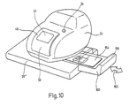
- Figure 10 shows the printer 24 when mounted on a third embodiment of a base station, which is in this drawing denoted with reference numeral 20".
- the base station 20" comprises a stop 150.
- the stop 150 is mounted to the main body of the base station 20" on which also the printer is placed.
- the stop 150 can be shifted by a user in the direction of arrow 152, ie. towards and away from the printer 24.
- the stop 150 is adjustable along the direction indicated by arrow 152.
- the right edge of the substrate to be printed can hence be aligned on a shoulder 156 of the stop 150.
- the stop 150 arrests at certain predetermined positions, as stops to be found in a hole punch. It would also be possible to have a single base station with a fixed stop.
Landscapes
- Accessory Devices And Overall Control Thereof (AREA)
- Printers Characterized By Their Purpose (AREA)
- Record Information Processing For Printing (AREA)
- Pile Receivers (AREA)
Claims (24)
- Drucker, umfassend:dadurch gekennzeichnet, dass der Drucker ferner eine Basisstation (20) zum Aufnehmen des Gehäuses (24) umfasst, wenn der Drucker nicht in Gebrauch ist, wodurch der Druckkopf (126) geschützt ist, wobei die Basisstation ein erstes Kabel (22) zum Versorgen des Druckkopfes mit Strom und Daten und ein zweites Kabel (18) zum Anschließen der Basisstation (20) an einen entfernt aufgestellten Computer aufweist.ein Gehäuse (24), das zum manuellen Positionieren auf einem Bildempfangsmedium (40) angeordnet ist, wobei das Gehäuse (24) mit einem Fenster (36) versehen ist;einen Druckkopf (126), der in dem Gehäuse vorgesehen ist;eine Druckfläche (11), die für das Bildempfangsmedium (40) freiliegt, wobei die Druckfläche (11) eine Zone definiert, in der der Druckkopf (126) zum Drucken eines gewünschten Musters auf das Bildempfangsmedium (40) betriebsfähig ist; wobei das Fenster (36) so angeordnet ist, dass die Druckfläche (11) durch das Fenster (36) sichtbar ist; und
- Drucker nach Anspruch 1, wobei ein Mittel zum Projizieren eines Lichtpunktes auf das Bildempfangsmedium (40) vorgesehen ist.
- Drucker nach Anspruch 2, wobei zwei Lichtpunkte auf das Bildempfangsmedium (40) projiziert werden und eine gedachte Linie, die beide Punkte verbindet, parallel zu einer Kante der Druckfläche (11) ausgerichtet ist.
- Drucker nach einem der Ansprüche 2 oder 3, wobei die Mittel (11) zum Projizieren eines Lichtpunktes eine LED und eine Fokussierlinse und/oder einen Festkörperlaser umfassen.
- Drucker nach Anspruch 1, wobei eine Visieranordnung (42') in dem Gehäuse (24) des Druckers vorgesehen ist, wobei die Visieranordnung (42') so angeordnet ist, dass die Druckfläche (11) dadurch gesehen werden kann, und zwei vertikal getrennte Bezugsmerkmale umfasst, vorzugsweise Fadenkreuze.
- Drucker nach Anspruch 5, wobei zwei Visieranordnungen (42') vorgesehen sind und eine gedachte Linie, die beide Visieranordnungen (42') verbindet, parallel zu einer Kante der Druckfläche (11) ausgerichtet ist.
- Drucker nach einem der vorhergehenden Ansprüche, wobei das Fenster (36) einen ersten und einen zweiten Bereich (44, 46) umfasst, wobei der erste Bereich (44) klar und der zweite Bereich (46) matt ist.
- Drucker nach Anspruch 7, wobei der erste Bereich (44) ungefähr rechteckig und vom zweiten Bereich (46) umgeben ist.
- Drucker nach einem der Ansprüche 7 oder 8, wobei der erste und der zweite Bereich (44, 46) des Fensters (36) so angeordnet sind, dass die Druckfläche (11) zumindest von einer größeren Entfernung vom Gehäuse (24) durch den ersten Bereich (44) sichtbar ist.
- Drucker nach einem der vorhergehenden Ansprüche, wobei das Fenster (36) gelenkig an dem Gehäuse (24) angebracht ist.
- Drucker nach Anspruch 10, wobei das Fenster (36) zwei Teile umfasst, die gelenkig aneinander angebracht sind.
- Drucker nach einem der Ansprüche 1 bis 9, wobei das Fenster (36) lösbar an dem Gehäuse (24) angebracht ist.
- Drucker nach einem der vorhergehenden Ansprüche, wobei die Druckfläche (11) von einer dünnen starren Führung (50) umgeben ist, die dünn genug ist, um eine Bewegung des Druckkopfes (126) innerhalb der Druckfläche (11) zu ermöglichen, und durch das Fenster (36) sichtbar ist.
- Drucker nach einem der Ansprüche 1 bis 12, wobei die Druckfläche (11) durch gelenkig angebrachte Druckbereichsführungen (52) umgeben ist, wobei die Druckbereichsführungen (52) so eingespannt sind, dass sie normal ausgerichtet von einer Ebene vertikal hoch stehen, die durch die Druckfläche (11) definiert ist, und angeordnet sind, um durch den Druckkopf (126) beiseite geschoben zu werden, und wobei die Druckbereichsführungen (52) durch das Fenster (36) sichtbar sind.
- Drucker nach Anspruch 14, wobei das Gelenk einstückig mit dem Gehäuse (24) geformt ist.
- Drucker nach einem der vorhergehenden Ansprüche,
wobei der Drucker weiterhin Folgendes umfasst:wobei das Steuergerät zum Erfassen von Markierungen (106) auf dem Bildempfangsmedium (40) betriebsfähig ist, wobei die Markierungen (106) mithilfe des Scanners gescannt werden, und das Steuergerät zum Anzeigen einer Information bezüglich einer Richtung, in die der Drucker bewegt werden soll, um eine Ausrichtung zwischen der Druckfläche (11) und den erfassten Markierungen (106) zu erzielen, betriebsfähig ist.einen Scanner, der zum Scannen der Druckfläche (11) betriebsfähig ist;ein Steuergerät, das an den Scanner, den Druckkopf (126) und ein Display (12) angeschlossen ist, wobei das Display im Gehäuse (24) des Druckers oder extern vom Drucker vorgesehen ist; - Drucker nach Anspruch 16, wobei der Scanner am Druckkopf (126) angebracht oder im Druckkopf (126) integriert ist.
- Drucker nach einem der Ansprüche 16 oder 17, wobei das Steuergerät gerade Linien (70) oder Schnittpunkte zwischen geraden Linien erfasst.
- Drucker nach einem der Ansprüche 16 bis 18, wobei das Display Pfeile und/oder blinkende LEDs zeigt, um anzuzeigen, in welche Richtung der Drucker bewegt werden soll.
- Drucker nach einem der Ansprüche 16 bis 19, wobei neben der Druckfläche (11) zwei räumlich getrennte Mauskugeln vorgesehen sind, wobei die Mauskugeln an das Steuergerät angeschlossen sind und eine Information bezüglich einer relativen Bewegung zwischen dem Drucker und dem Bildempfangsmedium (40) an das Steuergerät übermitteln und wobei das Steuergerät zum Vergleichen der Bewegung, die durch die Mauskugeln gemessen wird, mit einer Bewegung, die mithilfe von Daten, die vom Scanner erhalten werden, berechnet wird, und zum Anzeigen einer Information, wenn der Drucker in eine Position gebracht wurde, in der die Druckfläche (11) an den erfassten Markierungen (106) ausgerichtet ist, betriebfähig ist.
- Kombination eines Bildempfangsmediums (40) und des Druckers nach einem der vorhergehenden Ansprüche,
wobei das Bildempfangsmedium (40) mit vorgedruckten oder gelochten Ausrichtungsmarkierungen (106) zum Ausrichten des Druckers an dem Bildempfangsmedium (40) versehen ist. - Kombination nach Anspruch 21, wobei das Bildempfangsmedium (40) ein Etikettenstreifen ist.
- Kombination eines Bildempfangsmediums und des Druckers nach einem der Ansprüche 1 bis 20, wobei das Bildempfangsmedium (40) eine ID-Karte ist und der Drucker Ausrichtungsmarkierungen (106) auf die ID-Karte druckt, wobei die Ausrichtungsmarkierungen (106) zum Ausrichten der ID-Karte bei der folgenden Laminierung vorgesehen sind.
- Drucker nach einem der vorhergehenden Ansprüche 1 bis 20, wobei die Basisstation (20) mit einem Anschlag (150) versehen ist, der angeordnet ist, um ein Druckmedium (154) auf der Basisstation (20) in Bezug auf den Drucker auszurichten, und wobei die Position des Anschlags (150) einstellbar ist und eine Anzahl vorgegebener Positionen aufweist, an denen der Anschlag (150) festgestellt sein kann.
Priority Applications (1)
| Application Number | Priority Date | Filing Date | Title |
|---|---|---|---|
| EP02078599A EP1277589B1 (de) | 1998-11-13 | 1999-10-26 | Manuell positionierter Drucker mit Ausrichtungsmittel |
Applications Claiming Priority (3)
| Application Number | Priority Date | Filing Date | Title |
|---|---|---|---|
| GB9825018A GB2343656B (en) | 1998-11-13 | 1998-11-13 | A manually positioned printer with an alignment means |
| GB9825018 | 1998-11-13 | ||
| PCT/GB1999/003539 WO2000029221A1 (en) | 1998-11-13 | 1999-10-26 | A manually positioned printer with an alignment means |
Related Child Applications (1)
| Application Number | Title | Priority Date | Filing Date |
|---|---|---|---|
| EP02078599A Division EP1277589B1 (de) | 1998-11-13 | 1999-10-26 | Manuell positionierter Drucker mit Ausrichtungsmittel |
Publications (2)
| Publication Number | Publication Date |
|---|---|
| EP1128965A1 EP1128965A1 (de) | 2001-09-05 |
| EP1128965B1 true EP1128965B1 (de) | 2003-12-10 |
Family
ID=10842469
Family Applications (2)
| Application Number | Title | Priority Date | Filing Date |
|---|---|---|---|
| EP02078599A Expired - Lifetime EP1277589B1 (de) | 1998-11-13 | 1999-10-26 | Manuell positionierter Drucker mit Ausrichtungsmittel |
| EP99950991A Expired - Lifetime EP1128965B1 (de) | 1998-11-13 | 1999-10-26 | Positioniermittel für handdrucker |
Family Applications Before (1)
| Application Number | Title | Priority Date | Filing Date |
|---|---|---|---|
| EP02078599A Expired - Lifetime EP1277589B1 (de) | 1998-11-13 | 1999-10-26 | Manuell positionierter Drucker mit Ausrichtungsmittel |
Country Status (7)
| Country | Link |
|---|---|
| US (1) | US6674543B2 (de) |
| EP (2) | EP1277589B1 (de) |
| JP (1) | JP2002529290A (de) |
| AU (1) | AU6357499A (de) |
| DE (3) | DE69925764T2 (de) |
| GB (1) | GB2343656B (de) |
| WO (1) | WO2000029221A1 (de) |
Families Citing this family (36)
| Publication number | Priority date | Publication date | Assignee | Title |
|---|---|---|---|---|
| GB0011547D0 (en) * | 2000-05-12 | 2000-06-28 | Esselte Nv | A printer |
| JP3711868B2 (ja) * | 2000-05-31 | 2005-11-02 | カシオ計算機株式会社 | プリンタ内蔵マウス装置 |
| SE516503C2 (sv) | 2000-06-09 | 2002-01-22 | Print Dreams Europe Ab | Metod och anordning för en handhållen skrivaranordning |
| GB2372480A (en) * | 2001-01-30 | 2002-08-28 | Esselte Nv | Portable inkjet printer having a printer unit and a base station wherein the station includes an opening to receive an image receiving medium for printing |
| US6648528B2 (en) * | 2001-09-28 | 2003-11-18 | Hewlett-Packard Development Company, L.P. | Stationary media mobile printing |
| US7133168B2 (en) * | 2002-12-12 | 2006-11-07 | Xerox Corporation | Portable coilable electronic apparatus and method |
| US6991332B1 (en) | 2003-05-02 | 2006-01-31 | Fan Nong-Qiang | Digital hand stamp with memory to store multiple images |
| US7101097B2 (en) | 2003-07-28 | 2006-09-05 | Wessells Philip G | Apparatus and method for pad printing |
| US6971806B2 (en) * | 2003-07-28 | 2005-12-06 | Wessells Philip G | Apparatus, method, and computer program product for pad transfer |
| US6975827B2 (en) * | 2003-07-28 | 2005-12-13 | Wessells Philip G | Apparatus and method for image capture and pad transfer |
| US20050022686A1 (en) * | 2003-07-28 | 2005-02-03 | Dreampatch, Llc | Apparatus, method, and computer program product for animation pad transfer |
| JP4537676B2 (ja) * | 2003-08-07 | 2010-09-01 | 株式会社サトー | 印字ヘッドの識別機構 |
| US7869078B2 (en) * | 2003-12-18 | 2011-01-11 | Xerox Corporation | Reference marking system and tracking system for large area printing |
| US7513415B1 (en) * | 2004-07-29 | 2009-04-07 | Diebold Self-Service Systems | Cash dispensing automated banking machine deposit printing system and method |
| US7812994B2 (en) * | 2005-06-10 | 2010-10-12 | Marvell International Technology Ltd. | Handheld printer |
| US20070070395A1 (en) * | 2005-09-26 | 2007-03-29 | Lexmark International, Inc. | Handheld printer alert system |
| US7536533B2 (en) * | 2005-09-30 | 2009-05-19 | Silicon Laboratories Inc. | MCU based motor controller with pre-load register and DMA controller |
| US20070092324A1 (en) * | 2005-10-21 | 2007-04-26 | Studer Anthony D | Device and method for printing |
| US20070092325A1 (en) * | 2005-10-21 | 2007-04-26 | Studer Anthony D | Hand-held printing device |
| US7735951B2 (en) * | 2005-11-15 | 2010-06-15 | Lexmark International, Inc. | Alignment method for hand-operated printer |
| US7524051B2 (en) * | 2005-12-20 | 2009-04-28 | Lexmark International, Inc. | Hand-operated printer having a user interface |
| US7399129B2 (en) * | 2005-12-20 | 2008-07-15 | Lexmark International, Inc. | User interface for a hand-operated printer |
| US7748839B2 (en) * | 2006-05-09 | 2010-07-06 | Lexmark International, Inc. | Handheld printing with reference indicia |
| US7682017B2 (en) * | 2006-05-10 | 2010-03-23 | Lexmark International, Inc. | Handheld printer minimizing printing defects |
| JP4179354B2 (ja) * | 2006-07-21 | 2008-11-12 | セイコーエプソン株式会社 | 付箋紙供給装置および付箋紙プリンタ |
| US7938531B2 (en) | 2006-09-27 | 2011-05-10 | Lexmark International, Inc. | Methods and apparatus for handheld printing with optical positioning |
| US7748840B2 (en) * | 2006-09-27 | 2010-07-06 | Lexmark International, Inc. | Methods and apparatus for handheld printing with optical positioning |
| US7918519B2 (en) | 2006-09-27 | 2011-04-05 | Lexmark International, Inc. | Methods and apparatus for handheld printing with optical positioning |
| US7876472B2 (en) | 2006-10-12 | 2011-01-25 | Ricoh Co. Ltd. | Handheld printer and method of operation |
| US8123349B2 (en) | 2007-01-31 | 2012-02-28 | Hewlett-Packard Development Company, L.P. | Automatic image color and contrast optimization system based on cartridge identification |
| US8092006B2 (en) | 2007-06-22 | 2012-01-10 | Lexmark International, Inc. | Handheld printer configuration |
| US20090040286A1 (en) * | 2007-08-08 | 2009-02-12 | Tan Theresa Joy L | Print scheduling in handheld printers |
| US9225853B2 (en) | 2011-08-17 | 2015-12-29 | Empire Technology Development Llc | Visual images processed on portions of folded substrate |
| JP2017170807A (ja) * | 2016-03-24 | 2017-09-28 | カシオ計算機株式会社 | 印刷補助装置、印刷装置、印刷システム、報知方法及びプログラム |
| JP6911314B2 (ja) * | 2016-09-27 | 2021-07-28 | カシオ計算機株式会社 | 印刷装置、制御方法及びプログラム |
| JP6953815B2 (ja) * | 2017-06-13 | 2021-10-27 | 株式会社リコー | プログラム、情報処理装置、表示方法、液滴吐出装置、液滴吐出システム |
Family Cites Families (30)
| Publication number | Priority date | Publication date | Assignee | Title |
|---|---|---|---|---|
| FR2063988A1 (de) * | 1969-10-22 | 1971-07-16 | Mully Richard | |
| US3901372A (en) * | 1974-07-22 | 1975-08-26 | Teletype Corp | Protective cover with viewing window for printers |
| US4193684A (en) * | 1978-05-12 | 1980-03-18 | Armstrong Alvin H | Photographic printing and print identifying apparatus |
| JPS5619778A (en) * | 1979-07-27 | 1981-02-24 | Canon Inc | Printer |
| US4436439A (en) | 1980-08-27 | 1984-03-13 | Epson Corporation | Small printer |
| JPS57195671A (en) * | 1981-05-26 | 1982-12-01 | Canon Inc | Recording type electric equipment |
| DE3142937C2 (de) | 1981-10-29 | 1984-03-01 | Dieter Dipl.-Volksw. 7022 Leinfelden-Echterdingen Wesser | Handstempel mit einem elektrisch oder elektronisch steuerbaren Nadeldruckwerk |
| JPS61175056A (ja) * | 1985-01-31 | 1986-08-06 | Pentel Kk | ハンドプリンタ−による棒状体印字装置 |
| WO1986005142A1 (en) * | 1985-03-01 | 1986-09-12 | Benno Perren | Computer-controlled printing and marking device |
| US4819083A (en) * | 1986-01-31 | 1989-04-04 | Konishiroku Photo Industry Co., Ltd. | Moving type image recording apparatus |
| JPS62179965A (ja) * | 1986-02-04 | 1987-08-07 | Mitsubishi Electric Corp | 自力走行式プリンタ−装置 |
| JPS6353084A (ja) * | 1986-08-22 | 1988-03-07 | Canon Inc | 記録装置 |
| US5063451A (en) * | 1988-07-11 | 1991-11-05 | Canon Kabushiki Kaisha | Hand held recording apparatus with window on lower body portion for viewing recording position |
| JPH0226769A (ja) * | 1988-07-18 | 1990-01-29 | Nec Home Electron Ltd | 手動式印刷機 |
| US4949283A (en) * | 1988-12-28 | 1990-08-14 | Casio Computer Co., Ltd. | Manually sweepable printing apparatus |
| GB2236985A (en) * | 1989-10-10 | 1991-04-24 | David Heugh Hardy | Hand stamps for applying selective printing to articles |
| JPH03143657A (ja) * | 1989-10-31 | 1991-06-19 | Canon Inc | 手動走査式記録装置 |
| JP2551876Y2 (ja) * | 1991-09-06 | 1997-10-27 | ローム株式会社 | 携帯式プリンタを使用したテーププリンタ装置 |
| US5311208A (en) * | 1991-10-03 | 1994-05-10 | Xerox Corporation | Mouse that prints |
| JPH05108278A (ja) * | 1991-10-18 | 1993-04-30 | Brother Ind Ltd | キーボード付きコンパクトプリンタ |
| GB9207287D0 (en) * | 1992-04-02 | 1992-05-13 | Esselte Dymo Nv | Printing device |
| DE4237275C1 (de) * | 1992-11-05 | 1993-11-04 | Dorothea Wolf | Stempel |
| JPH0752428A (ja) * | 1993-08-21 | 1995-02-28 | Sony Corp | 印刷装置 |
| JPH0876680A (ja) * | 1994-09-02 | 1996-03-22 | Fujitsu Ltd | 管理教育システム |
| JPH09109466A (ja) * | 1995-10-13 | 1997-04-28 | Brother Ind Ltd | 走査式印字装置 |
| US5634730A (en) | 1995-11-06 | 1997-06-03 | Bobry; Howard H. | Hand-held electronic printer |
| JPH09131927A (ja) * | 1995-11-09 | 1997-05-20 | Brother Ind Ltd | 印字装置 |
| US5825995A (en) * | 1996-03-11 | 1998-10-20 | Intermec Technologies, Inc. | Printer with motion detection |
| JPH09286139A (ja) * | 1996-04-24 | 1997-11-04 | Brother Ind Ltd | 印字装置 |
| GB9825024D0 (en) * | 1998-11-13 | 1999-01-13 | Esselte Nv | A printer with failsafe features |
-
1998
- 1998-11-13 GB GB9825018A patent/GB2343656B/en not_active Expired - Fee Related
-
1999
- 1999-10-26 DE DE69925764T patent/DE69925764T2/de not_active Expired - Lifetime
- 1999-10-26 AU AU63574/99A patent/AU6357499A/en not_active Abandoned
- 1999-10-26 EP EP02078599A patent/EP1277589B1/de not_active Expired - Lifetime
- 1999-10-26 EP EP99950991A patent/EP1128965B1/de not_active Expired - Lifetime
- 1999-10-26 WO PCT/GB1999/003539 patent/WO2000029221A1/en active IP Right Grant
- 1999-10-26 DE DE69913562T patent/DE69913562T2/de not_active Expired - Lifetime
- 1999-10-26 DE DE29923983U patent/DE29923983U1/de not_active Expired - Lifetime
- 1999-10-26 JP JP2000582239A patent/JP2002529290A/ja not_active Withdrawn
-
2001
- 2001-05-14 US US09/853,804 patent/US6674543B2/en not_active Expired - Fee Related
Also Published As
| Publication number | Publication date |
|---|---|
| GB9825018D0 (en) | 1999-01-06 |
| DE69925764T2 (de) | 2006-03-23 |
| DE69913562D1 (de) | 2004-01-22 |
| EP1277589A1 (de) | 2003-01-22 |
| GB2343656B (en) | 2002-11-13 |
| WO2000029221A1 (en) | 2000-05-25 |
| US6674543B2 (en) | 2004-01-06 |
| DE69925764D1 (de) | 2005-07-14 |
| JP2002529290A (ja) | 2002-09-10 |
| EP1277589B1 (de) | 2005-06-08 |
| DE29923983U1 (de) | 2001-07-12 |
| AU6357499A (en) | 2000-06-05 |
| US20020030830A1 (en) | 2002-03-14 |
| EP1128965A1 (de) | 2001-09-05 |
| GB2343656A (en) | 2000-05-17 |
| DE69913562T2 (de) | 2004-09-16 |
Similar Documents
| Publication | Publication Date | Title |
|---|---|---|
| EP1128965B1 (de) | Positioniermittel für handdrucker | |
| US6499840B2 (en) | Multi-functional printer | |
| EP1000758B1 (de) | Ausfallsicherer Drucker | |
| US7413301B2 (en) | Inkjet printing apparatus with multiple platens | |
| US6367993B2 (en) | Printer system | |
| AU673080B2 (en) | Printing apparatus | |
| US5223939A (en) | Printer having a mark printing function for printing marks indicative of cut positions | |
| US7524051B2 (en) | Hand-operated printer having a user interface | |
| US20080069620A1 (en) | Hand-operated Printer and Printer Dock Configured to Facilitate Auxiliary Printing | |
| US20060227161A1 (en) | Printing apparatus and printing system | |
| US7625146B2 (en) | Method and system for custom paper cutting | |
| EP2045083B1 (de) | Etikettdatenerstellungsvorrichtung, Etikettdatenerstellungsverfahren und Computerprogrammprodukt | |
| US20060024115A1 (en) | Printing apparatus and print control apparatus | |
| JP4321331B2 (ja) | テープ印刷装置 | |
| EP2314457A1 (de) | Druckvorrichtung | |
| EP1231561B1 (de) | Drucksystem | |
| KR100721989B1 (ko) | 커팅 플로터용의 레지스터 마크 판독장치 및 레지스터 마크판독방법 | |
| JPH11240209A (ja) | ドットインパクトプリンタ | |
| JP2021122973A (ja) | 印刷装置、プログラムおよび印刷物の生産方法 | |
| JP2005335245A (ja) | 印刷方法、印刷装置、インク吸着部材及びトレイ |
Legal Events
| Date | Code | Title | Description |
|---|---|---|---|
| PUAI | Public reference made under article 153(3) epc to a published international application that has entered the european phase |
Free format text: ORIGINAL CODE: 0009012 |
|
| 17P | Request for examination filed |
Effective date: 20010427 |
|
| AK | Designated contracting states |
Kind code of ref document: A1 Designated state(s): AT BE CH CY DE DK ES FI FR GB GR IE IT LI LU MC NL PT SE |
|
| AX | Request for extension of the european patent |
Free format text: AL;LT;LV;MK;RO;SI |
|
| 17Q | First examination report despatched |
Effective date: 20020424 |
|
| GRAH | Despatch of communication of intention to grant a patent |
Free format text: ORIGINAL CODE: EPIDOS IGRA |
|
| GRAS | Grant fee paid |
Free format text: ORIGINAL CODE: EPIDOSNIGR3 |
|
| GRAA | (expected) grant |
Free format text: ORIGINAL CODE: 0009210 |
|
| AK | Designated contracting states |
Kind code of ref document: B1 Designated state(s): DE FR GB |
|
| REG | Reference to a national code |
Ref country code: GB Ref legal event code: FG4D |
|
| REF | Corresponds to: |
Ref document number: 69913562 Country of ref document: DE Date of ref document: 20040122 Kind code of ref document: P |
|
| ET | Fr: translation filed | ||
| PLBE | No opposition filed within time limit |
Free format text: ORIGINAL CODE: 0009261 |
|
| STAA | Information on the status of an ep patent application or granted ep patent |
Free format text: STATUS: NO OPPOSITION FILED WITHIN TIME LIMIT |
|
| 26N | No opposition filed |
Effective date: 20040913 |
|
| REG | Reference to a national code |
Ref country code: FR Ref legal event code: CD |
|
| PGFP | Annual fee paid to national office [announced via postgrant information from national office to epo] |
Ref country code: DE Payment date: 20091022 Year of fee payment: 11 |
|
| PGFP | Annual fee paid to national office [announced via postgrant information from national office to epo] |
Ref country code: GB Payment date: 20091021 Year of fee payment: 11 Ref country code: FR Payment date: 20091029 Year of fee payment: 11 |
|
| GBPC | Gb: european patent ceased through non-payment of renewal fee |
Effective date: 20101026 |
|
| PG25 | Lapsed in a contracting state [announced via postgrant information from national office to epo] |
Ref country code: FR Free format text: LAPSE BECAUSE OF NON-PAYMENT OF DUE FEES Effective date: 20101102 |
|
| REG | Reference to a national code |
Ref country code: FR Ref legal event code: ST Effective date: 20110630 |
|
| REG | Reference to a national code |
Ref country code: DE Ref legal event code: R119 Ref document number: 69913562 Country of ref document: DE Effective date: 20110502 |
|
| PG25 | Lapsed in a contracting state [announced via postgrant information from national office to epo] |
Ref country code: GB Free format text: LAPSE BECAUSE OF NON-PAYMENT OF DUE FEES Effective date: 20101026 |
|
| PG25 | Lapsed in a contracting state [announced via postgrant information from national office to epo] |
Ref country code: DE Free format text: LAPSE BECAUSE OF NON-PAYMENT OF DUE FEES Effective date: 20110502 |