EP1128005A2 - Poignée de porte pour véhicule - Google Patents
Poignée de porte pour véhicule Download PDFInfo
- Publication number
- EP1128005A2 EP1128005A2 EP01104178A EP01104178A EP1128005A2 EP 1128005 A2 EP1128005 A2 EP 1128005A2 EP 01104178 A EP01104178 A EP 01104178A EP 01104178 A EP01104178 A EP 01104178A EP 1128005 A2 EP1128005 A2 EP 1128005A2
- Authority
- EP
- European Patent Office
- Prior art keywords
- handle
- switch
- control portion
- lever
- lock
- Prior art date
- Legal status (The legal status is an assumption and is not a legal conclusion. Google has not performed a legal analysis and makes no representation as to the accuracy of the status listed.)
- Withdrawn
Links
Images

Classifications
-
- E—FIXED CONSTRUCTIONS
- E05—LOCKS; KEYS; WINDOW OR DOOR FITTINGS; SAFES
- E05B—LOCKS; ACCESSORIES THEREFOR; HANDCUFFS
- E05B81/00—Power-actuated vehicle locks
- E05B81/54—Electrical circuits
- E05B81/64—Monitoring or sensing, e.g. by using switches or sensors
- E05B81/76—Detection of handle operation; Detection of a user approaching a handle; Electrical switching actions performed by door handles
- E05B81/78—Detection of handle operation; Detection of a user approaching a handle; Electrical switching actions performed by door handles as part of a hands-free locking or unlocking operation
-
- E—FIXED CONSTRUCTIONS
- E05—LOCKS; KEYS; WINDOW OR DOOR FITTINGS; SAFES
- E05B—LOCKS; ACCESSORIES THEREFOR; HANDCUFFS
- E05B81/00—Power-actuated vehicle locks
- E05B81/54—Electrical circuits
- E05B81/64—Monitoring or sensing, e.g. by using switches or sensors
- E05B81/76—Detection of handle operation; Detection of a user approaching a handle; Electrical switching actions performed by door handles
-
- E—FIXED CONSTRUCTIONS
- E05—LOCKS; KEYS; WINDOW OR DOOR FITTINGS; SAFES
- E05B—LOCKS; ACCESSORIES THEREFOR; HANDCUFFS
- E05B85/00—Details of vehicle locks not provided for in groups E05B77/00 - E05B83/00
- E05B85/10—Handles
- E05B85/14—Handles pivoted about an axis parallel to the wing
- E05B85/16—Handles pivoted about an axis parallel to the wing a longitudinal grip part being pivoted at one end about an axis perpendicular to the longitudinal axis of the grip part
Definitions
- the present invention relates to a vehicle door handle.
- Vehicle doors in general, and motor vehicle doors in particular, are opened by means of a handle, wherein an elongated frame is fitted inside the door and supports a control lever, which has a control end portion connected, in use, to the relative lock, and an opposite end portion connected to the frame by a hinge having a normally vertical axis of rotation, so as to rotate about the hinge axis between a withdrawn rest position and an extracted position releasing the lock.
- More and more modern vehicles are equipped with electronic devices for remote controlling each door lock and, in particular, activating or deactivating the security function of the lock without using the key.
- a transmitter or so-called 'badge' is used, which is carried by the user of the vehicle and provides for transmitting signals to a central control unit on the vehicle, which, on receiving and recognizing the signals, deactivates the security function of the lock.
- the same transmitter can also be used to activate the security function of the lock. That is, when the transmitter is a given distance from the vehicle, the central control unit is no longer able to receive the signals emitted by the transmitter, and can be programmed to automatically activate the security function of the lock in the absence of a signal.
- the above electronic device has the drawback that, in most cases, the user of the vehicle wishes to activate the security function of the lock immediately, without waiting for it to be done automatically when the transmitter is a given distance from the vehicle.
- a handle comprising a switch located inside the frame, just beneath the end portion of the lever hinged to the frame, so that the switching member of the switch is movable directly by the end portion of the lever.
- the hinge interposed between the frame and the end portion of the lever is so formed as to permit not only rotation but also radial displacement of the end portion inwards of the door from the rest position to a switching position, so as to trip the switch and so activate the security function of the lock.
- the switch is easily damaged and subject to malfunctioning, on account of said displacement inwards of the door necessarily requiring, between the frame and the end of the lever in the rest position, a certain amount of clearance by which the switch communicates directly with the outside environment, especially in the event the complex seal provided is not positioned correctly or is damaged, e.g. by normal operation of the lever.
- the lever is maintained in the rest position by a thrust spring acting directly on the lever itself, and which is often stressed even when releasing the lock, and the efficiency and reliability of which is gradually impaired by external agents, so that very often the security function of the lock remains permanently activated.
- the handle itself is complex in design, on account of the particular hinge and seal used, as well as the presence of elastic thrust elements, so that, in the event of a fault on the switch and/or spring, replacing the switch or spring is a particularly awkward, relatively time-consuming and, hence, expensive job.
- a handle for a vehicle door comprising a frame fittable to said door; a manual control lever hinged to said frame and comprising a control portion, which engages in sliding manner a passage, formed in the frame, for mechanical connection to a lock on said door; and electric control means for electrically controlling said lock to activate a security function of the lock;
- the electric control means comprising a switch, and push-button activating means for activating said switch; characterized in that said switch is located to the side of said passage; and said push-button activating means comprise said control portion, and transmission means interposed between said control portion and said switch; flexible positioning means being provided to keep said control portion in an intermediate rest position between an extracted position releasing the lock and a forward position switching said switch.
- Number 1 in Figure 1 indicates as a whole a handle connectable to a body 2 of a door 3 (shown partly) of a vehicle (not shown) to control a lock 4 on door 3.
- Handle 1 comprises a frame 5 fittable inside door 3; a body 6 for supporting a key assembly (not shown) and connected in known manner to an end portion 5a of frame 5; and a substantially L-shaped lever 7, which is gripped by the user of the vehicle. More specifically, lever 7 comprises an elongated portion or grip 8 having an end portion (not shown) hinged to an end portion of frame 5, longitudinally opposite portion 5a, so as to rotate, with respect to frame 5, about a hinge axis (not shown); and an elongated control portion 9 integral with a portion of portion 8 adjacent to body 6. Control portion 9 extends through frame 5 in a direction substantially perpendicular to portion 8, loosely engages a passage 10 formed through frame 5, and terminates at the free end with a pin 12. Pin 12 projects facing portion 8, and is fitted with a known lever 13 connected to lock 4 by a Bowden cable 14, which, together with levers 7 and 13, defines as assembly 15 for mechanically activating lock 4.
- handle 1 also comprises an electric control assembly 16 for activating the security function of lock 4.
- Assembly 16 comprises a known push-button switch 18 located to the side of passage 10 and housed inside a cavity 19 in frame 5, an inner wall 20 of which cavity defines passage 10 and extends partly facing pin 12.
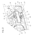
- switch 18 is connected releasably to frame 5 by two, elastic appendixes 21 terminating with respective retaining teeth 22 which click on to switch 18 ( Figure 2).
- Switch 18 is also connected electrically in known manner to a central control unit (not shown) for controlling activation of the security function of the lock, and is controlled by a push-button activating device 23 user-operated manually from the outside and forming part of assembly 16.
- Transmission 24 comprises a single rocker arm lever 25, which extends astride wall 20, is substantially parallel to pin 12, and has an intermediate portion 26 adjacent to wall 20 and hinged to frame 5 by a hinge 27 to swing about a hinge axis 28 perpendicular to pin 12 and parallel to the hinge axis (not shown) of lever 7.
- Rocker arm lever 25 also comprises two opposite end portions 29 and 30, portion 29 extending facing a free end portion of pin 12, and portion 30 extending facing the movable member of switch 18.
- hinge 27 comprises a fork, the arms 31 of which, integral with frame 5, define respective cylindrical seats 32 coaxial with axis 28 and engaged in rotary manner by respective opposite hinge pins 33 integral with intermediate portion 26 and which click inside seats 32.
- Each of pins 33 is wound with a respective intermediate portion of a known wire torsion spring 35 having two opposite end portions resting one on frame 5 and the other on an inner surface of end portion 30 to keep end portion 30 detached from switch 18, as shown in Figure 1, and to force a supporting surface 37 of portion 29 against pin 12 to keep lever 7, and hence control portion 9, in an intermediate rest position (Figure 1) between an extracted position controlling lock 4 - wherein control portion 9 extends partly outside passage 10 and releases lock 4 - and a forward position activating the security function of lock 4 - wherein portion 9 is pushed towards frame 5 and rocker arm lever 25 is rotated as shown by the dash and dot line in Figure 1.
- lever 7 is also maintained in the intermediate rest position by a flexible member 39, which is located parallel to the lever 25-spring 35 assembly, is connected to lever 7, and comprises a rigid contoured supporting portion 40 resting on an outer surface of body 2, and a collar portion 41, which is made of flexible, e.g. elastomeric, material, is integral with supporting portion 40, and extends towards and contacts the inner surface 8a of portion 8 of lever 7. More specifically, collar portion 41 comprises two flat longitudinal walls 43 facing and parallel to each other; and a flat transverse wall 44 extending facing control portion 9 and connecting longitudinal walls 43 to each other.
- portion 8 may be gripped to move lever 7 into the extracted position and release lock 4, or to push control portion 9 inwards of door 3, in opposition to the elastic resistance of spring 35 and portion 41 of member 39, and, by means of control portion 9, rotate lever 25 in the opposite direction into the withdrawn position activating the security function of the lock and wherein portion 30 of rocker arm lever 25 trips switch 18.
- handle 1 is, first of all, extremely straightforward in design, by lever 7 being simply hinged to frame 5 to rotate about a fixed hinge axis, and being of the same design as levers normally used in known handles.
- switch 18 is fitted to frame 5 in a position in which it can be reached and removed easily from inside the door, and is controlled by a straightforward lever transmission activated directly by control portion 9 and which provides for both switching switch 18 and keeping lever 7 in the intermediate rest position.
- a straightforward lever transmission activated directly by control portion 9 and which provides for both switching switch 18 and keeping lever 7 in the intermediate rest position.
- using a straightforward lever transmission enables switch 18 to be located to the side of and at a distance from passage 10 of control portion 9, and in particular inside a cavity 19 open inwards of the door, so that any external agents infiltrating passage 10 have no effect whatsoever on switch 18, the reliability and efficiency of which therefore remains unchanged over time.
- lever 7 being maintained in the intermediate rest position by both the mechanical transmission and the elastomeric member, which are located parallel to cooperate synergically, and are so formed as to adapt to each other with no manual adjustment required.
- member 39 also enables it to act, not only as an elastically deformable member to keep lever 7 in the intermediate rest position, but also as a sealing member, by portion 41 of member 39 always being forced against lever 7 in the intermediate rest position or the withdrawn security function activating position.
- switch 18 may be located otherwise than as shown, providing it is some distance from passage 10; rocker arm lever 25 may be replaced with a different mechanical transmission, providing it is activated by pushing the portion of lever 7 adjacent to supporting body 6 inwards of the door; and, finally, provision may be made, between lever 7 and the door body, for a retaining and sealing member other than the one described and even performing only one of the functions performed by member 39.
Landscapes
- Lock And Its Accessories (AREA)
Applications Claiming Priority (2)
| Application Number | Priority Date | Filing Date | Title |
|---|---|---|---|
| ITTO000175 | 2000-02-23 | ||
| IT2000TO000175A IT1319907B1 (it) | 2000-02-23 | 2000-02-23 | Maniglia per una portiera di un veicolo. |
Publications (2)
| Publication Number | Publication Date |
|---|---|
| EP1128005A2 true EP1128005A2 (fr) | 2001-08-29 |
| EP1128005A3 EP1128005A3 (fr) | 2002-06-05 |
Family
ID=11457475
Family Applications (1)
| Application Number | Title | Priority Date | Filing Date |
|---|---|---|---|
| EP01104178A Withdrawn EP1128005A3 (fr) | 2000-02-23 | 2001-02-21 | Poignée de porte pour véhicule |
Country Status (4)
| Country | Link |
|---|---|
| US (1) | US20020046440A1 (fr) |
| EP (1) | EP1128005A3 (fr) |
| JP (1) | JP2001288935A (fr) |
| IT (1) | IT1319907B1 (fr) |
Cited By (4)
| Publication number | Priority date | Publication date | Assignee | Title |
|---|---|---|---|---|
| DE102004054189A1 (de) * | 2004-11-10 | 2006-05-11 | Bayerische Motoren Werke Ag | Verstellbarer Türgriff, insbesondere an einer Kraftfahrzeugtür |
| DE102004058874A1 (de) * | 2004-12-06 | 2006-06-08 | Huf Hülsbeck & Fürst Gmbh & Co. Kg | Türaußengriff für ein Kraftfahrzeug |
| WO2007042233A3 (fr) * | 2005-10-11 | 2007-11-29 | Huf Huelsbeck & Fuerst Gmbh | Dispositif pour ouvrir des serrures sur des portieres ou des hayons de vehicules |
| US20210010303A1 (en) * | 2019-07-08 | 2021-01-14 | U-Shin Italia S.P.A. | Door leaf handle for a motor vehicle |
Families Citing this family (9)
| Publication number | Priority date | Publication date | Assignee | Title |
|---|---|---|---|---|
| US8601903B1 (en) * | 1999-09-14 | 2013-12-10 | Huf Hülsbeck & Fürst Gmbh & Co. Kg | Closing system, especially for motor vehicles |
| JP2005299085A (ja) * | 2004-04-06 | 2005-10-27 | Honda Motor Co Ltd | ドアアウトサイドハンドル |
| US20060010943A1 (en) * | 2004-07-13 | 2006-01-19 | Lear Corporation | Mechanical handle switch assembly |
| GB2416186B (en) * | 2004-07-12 | 2007-04-04 | Lear Corp | Mechanical handle switch assembly |
| US8505241B2 (en) * | 2005-12-08 | 2013-08-13 | Nissan Motor Co., Ltd. | Door lever for controlling a door opening and closing apparatus |
| US9404292B2 (en) * | 2012-07-11 | 2016-08-02 | Huf North America Automotive Parts Mfg. Corp. | Vehicular door handle assembly with deployable latch connection |
| US9394729B2 (en) * | 2012-07-11 | 2016-07-19 | Huf North America Automotive Parts Mfg. Corp. | Vehicular door handle assembly with electrically deployable latch connection |
| JP5955303B2 (ja) * | 2013-11-19 | 2016-07-20 | 株式会社小糸製作所 | ドアハンドル |
| DE102021000442B4 (de) | 2021-01-29 | 2022-12-08 | Mercedes-Benz Group AG | Türgriff zur Türschlossbetätigung, insbesondere für ein Fahrzeug |
Citations (4)
| Publication number | Priority date | Publication date | Assignee | Title |
|---|---|---|---|---|
| US4738334A (en) * | 1985-10-11 | 1988-04-19 | Bayerische Motoren Werke, Ag | Security installation for motor vehicles |
| EP0916789A1 (fr) * | 1997-11-12 | 1999-05-19 | Robert Bosch Gmbh | Système de verrouillage de porte avec dispositif pour verrouiller et déverrouiller une serrure de porte |
| EP0927803A1 (fr) * | 1997-12-05 | 1999-07-07 | Kabushiki Kaisha Tokai Rika Denki Seisakusho | Dispositif de déverrouillage de porte pour véhicule |
| EP1111165A1 (fr) * | 1999-12-23 | 2001-06-27 | Valeo Sécurité Habitacle | Poignée d'ouvrant de véhicule automobile comportant des moyens perfectionnés d'actionnement des organes de commutation |
-
2000
- 2000-02-23 IT IT2000TO000175A patent/IT1319907B1/it active
-
2001
- 2001-02-21 EP EP01104178A patent/EP1128005A3/fr not_active Withdrawn
- 2001-02-22 US US09/791,485 patent/US20020046440A1/en not_active Abandoned
- 2001-02-23 JP JP2001048662A patent/JP2001288935A/ja active Pending
Patent Citations (4)
| Publication number | Priority date | Publication date | Assignee | Title |
|---|---|---|---|---|
| US4738334A (en) * | 1985-10-11 | 1988-04-19 | Bayerische Motoren Werke, Ag | Security installation for motor vehicles |
| EP0916789A1 (fr) * | 1997-11-12 | 1999-05-19 | Robert Bosch Gmbh | Système de verrouillage de porte avec dispositif pour verrouiller et déverrouiller une serrure de porte |
| EP0927803A1 (fr) * | 1997-12-05 | 1999-07-07 | Kabushiki Kaisha Tokai Rika Denki Seisakusho | Dispositif de déverrouillage de porte pour véhicule |
| EP1111165A1 (fr) * | 1999-12-23 | 2001-06-27 | Valeo Sécurité Habitacle | Poignée d'ouvrant de véhicule automobile comportant des moyens perfectionnés d'actionnement des organes de commutation |
Cited By (5)
| Publication number | Priority date | Publication date | Assignee | Title |
|---|---|---|---|---|
| DE102004054189A1 (de) * | 2004-11-10 | 2006-05-11 | Bayerische Motoren Werke Ag | Verstellbarer Türgriff, insbesondere an einer Kraftfahrzeugtür |
| DE102004058874A1 (de) * | 2004-12-06 | 2006-06-08 | Huf Hülsbeck & Fürst Gmbh & Co. Kg | Türaußengriff für ein Kraftfahrzeug |
| WO2007042233A3 (fr) * | 2005-10-11 | 2007-11-29 | Huf Huelsbeck & Fuerst Gmbh | Dispositif pour ouvrir des serrures sur des portieres ou des hayons de vehicules |
| EP2669453A1 (fr) * | 2005-10-11 | 2013-12-04 | Huf Hülsbeck & Fürst GmbH & Co. KG | Dispositif pour ouvrir des serrures de portes et d'ouvrants de véhicules |
| US20210010303A1 (en) * | 2019-07-08 | 2021-01-14 | U-Shin Italia S.P.A. | Door leaf handle for a motor vehicle |
Also Published As
| Publication number | Publication date |
|---|---|
| US20020046440A1 (en) | 2002-04-25 |
| EP1128005A3 (fr) | 2002-06-05 |
| IT1319907B1 (it) | 2003-11-12 |
| ITTO20000175A1 (it) | 2001-08-23 |
| JP2001288935A (ja) | 2001-10-19 |
| ITTO20000175A0 (it) | 2000-02-23 |
Similar Documents
| Publication | Publication Date | Title |
|---|---|---|
| EP1128005A2 (fr) | Poignée de porte pour véhicule | |
| US10920465B2 (en) | Interior door lock operator integrated into pull door handle | |
| JP4656942B2 (ja) | 慣性による安全システムを備える車両用のドアハンドル | |
| EP2619389B1 (fr) | Dispositif de poignée de portière de véhicule | |
| US8342583B2 (en) | Vehicle panel control system | |
| EP1162332B1 (fr) | Poignée de porte pour véhicule | |
| EP0999324A2 (fr) | Poignée pour une serrure de véhicule | |
| US5947536A (en) | Latch device for a tailgate of a vehicle | |
| CN109072642B (zh) | 用于打开机动车上的车门或舱盖的打开设备 | |
| US20120247161A1 (en) | Flush handle device for a door of a vehicle | |
| EP2620569B1 (fr) | Système de libération d'un pêne pour porte de véhicule | |
| JPS6252885B2 (fr) | ||
| CN112204217B (zh) | 门扇把手装置,特别是用于机动车辆的 | |
| CN113700399B (zh) | 致动器和用于车辆的门的车门致动系统 | |
| US20210363793A1 (en) | Door handle assembly for a vehicle door | |
| US8851533B2 (en) | Vehicle door locking device | |
| EP1128002A2 (fr) | Poignée de porte pour véhicule | |
| US20200332575A1 (en) | Door handle assembly of a motor vehicle | |
| US20080016777A1 (en) | Emergency release | |
| JP3600038B2 (ja) | オープナー装置 | |
| CN113195855A (zh) | 车门把手 | |
| EP1081319B1 (fr) | Poignée de véhicule automobile | |
| EP1128003A1 (fr) | Poignée de porte pour véhicule | |
| JP2005330752A (ja) | ドアハンドルユニット | |
| US20230313571A1 (en) | Actuating Mechanism for Actuating Covers for Vehicles |
Legal Events
| Date | Code | Title | Description |
|---|---|---|---|
| PUAI | Public reference made under article 153(3) epc to a published international application that has entered the european phase |
Free format text: ORIGINAL CODE: 0009012 |
|
| AK | Designated contracting states |
Kind code of ref document: A2 Designated state(s): AT BE CH CY DE DK ES FI FR GB GR IE IT LI LU MC NL PT SE TR |
|
| AX | Request for extension of the european patent |
Free format text: AL;LT;LV;MK;RO;SI |
|
| PUAL | Search report despatched |
Free format text: ORIGINAL CODE: 0009013 |
|
| AK | Designated contracting states |
Kind code of ref document: A3 Designated state(s): AT BE CH CY DE DK ES FI FR GB GR IE IT LI LU MC NL PT SE TR |
|
| AX | Request for extension of the european patent |
Free format text: AL;LT;LV;MK;RO;SI |
|
| 17P | Request for examination filed |
Effective date: 20021205 |
|
| AKX | Designation fees paid |
Designated state(s): DE ES FR GB SE |
|
| 17Q | First examination report despatched |
Effective date: 20030908 |
|
| STAA | Information on the status of an ep patent application or granted ep patent |
Free format text: STATUS: THE APPLICATION IS DEEMED TO BE WITHDRAWN |
|
| 18D | Application deemed to be withdrawn |
Effective date: 20040319 |