EP1127821B1 - Vorrichtung und Verfahren zum Verbinden von Folienrollen - Google Patents
Vorrichtung und Verfahren zum Verbinden von Folienrollen Download PDFInfo
- Publication number
- EP1127821B1 EP1127821B1 EP01200627A EP01200627A EP1127821B1 EP 1127821 B1 EP1127821 B1 EP 1127821B1 EP 01200627 A EP01200627 A EP 01200627A EP 01200627 A EP01200627 A EP 01200627A EP 1127821 B1 EP1127821 B1 EP 1127821B1
- Authority
- EP
- European Patent Office
- Prior art keywords
- film
- connecting members
- cutter
- pair
- movable
- Prior art date
- Legal status (The legal status is an assumption and is not a legal conclusion. Google has not performed a legal analysis and makes no representation as to the accuracy of the status listed.)
- Expired - Lifetime
Links
Images


Classifications
-
- B—PERFORMING OPERATIONS; TRANSPORTING
- B65—CONVEYING; PACKING; STORING; HANDLING THIN OR FILAMENTARY MATERIAL
- B65H—HANDLING THIN OR FILAMENTARY MATERIAL, e.g. SHEETS, WEBS, CABLES
- B65H19/00—Changing the web roll
- B65H19/10—Changing the web roll in unwinding mechanisms or in connection with unwinding operations
- B65H19/18—Attaching, e.g. pasting, the replacement web to the expiring web
- B65H19/1857—Support arrangement of web rolls
- B65H19/1873—Support arrangement of web rolls with two stationary roll supports carrying alternately the replacement and the expiring roll
-
- B—PERFORMING OPERATIONS; TRANSPORTING
- B65—CONVEYING; PACKING; STORING; HANDLING THIN OR FILAMENTARY MATERIAL
- B65H—HANDLING THIN OR FILAMENTARY MATERIAL, e.g. SHEETS, WEBS, CABLES
- B65H19/00—Changing the web roll
- B65H19/10—Changing the web roll in unwinding mechanisms or in connection with unwinding operations
- B65H19/18—Attaching, e.g. pasting, the replacement web to the expiring web
- B65H19/1842—Attaching, e.g. pasting, the replacement web to the expiring web standing splicing, i.e. the expiring web being stationary during splicing contact
- B65H19/1852—Attaching, e.g. pasting, the replacement web to the expiring web standing splicing, i.e. the expiring web being stationary during splicing contact taking place at a distance from the replacement roll
-
- B—PERFORMING OPERATIONS; TRANSPORTING
- B65—CONVEYING; PACKING; STORING; HANDLING THIN OR FILAMENTARY MATERIAL
- B65H—HANDLING THIN OR FILAMENTARY MATERIAL, e.g. SHEETS, WEBS, CABLES
- B65H2301/00—Handling processes for sheets or webs
- B65H2301/40—Type of handling process
- B65H2301/46—Splicing
- B65H2301/461—Processing webs in splicing process
- B65H2301/4615—Processing webs in splicing process after splicing
- B65H2301/4617—Processing webs in splicing process after splicing cutting webs in splicing process
- B65H2301/46172—Processing webs in splicing process after splicing cutting webs in splicing process cutting expiring web only
-
- B—PERFORMING OPERATIONS; TRANSPORTING
- B65—CONVEYING; PACKING; STORING; HANDLING THIN OR FILAMENTARY MATERIAL
- B65H—HANDLING THIN OR FILAMENTARY MATERIAL, e.g. SHEETS, WEBS, CABLES
- B65H2301/00—Handling processes for sheets or webs
- B65H2301/40—Type of handling process
- B65H2301/46—Splicing
- B65H2301/462—Form of splice
- B65H2301/4622—Abutting article or web portions, i.e. edge to edge
-
- B—PERFORMING OPERATIONS; TRANSPORTING
- B65—CONVEYING; PACKING; STORING; HANDLING THIN OR FILAMENTARY MATERIAL
- B65H—HANDLING THIN OR FILAMENTARY MATERIAL, e.g. SHEETS, WEBS, CABLES
- B65H2301/00—Handling processes for sheets or webs
- B65H2301/40—Type of handling process
- B65H2301/46—Splicing
- B65H2301/463—Splicing splicing means, i.e. means by which a web end is bound to another web end
- B65H2301/4631—Adhesive tape
-
- B—PERFORMING OPERATIONS; TRANSPORTING
- B65—CONVEYING; PACKING; STORING; HANDLING THIN OR FILAMENTARY MATERIAL
- B65H—HANDLING THIN OR FILAMENTARY MATERIAL, e.g. SHEETS, WEBS, CABLES
- B65H2301/00—Handling processes for sheets or webs
- B65H2301/40—Type of handling process
- B65H2301/46—Splicing
- B65H2301/464—Splicing effecting splice
- B65H2301/46412—Splicing effecting splice by element moving in a direction perpendicular to the running direction of the web
-
- B—PERFORMING OPERATIONS; TRANSPORTING
- B65—CONVEYING; PACKING; STORING; HANDLING THIN OR FILAMENTARY MATERIAL
- B65H—HANDLING THIN OR FILAMENTARY MATERIAL, e.g. SHEETS, WEBS, CABLES
- B65H2406/00—Means using fluid
- B65H2406/30—Suction means
- B65H2406/35—Other elements with suction surface, e.g. plate or wall
- B65H2406/351—Other elements with suction surface, e.g. plate or wall facing the surface of the handled material
-
- Y—GENERAL TAGGING OF NEW TECHNOLOGICAL DEVELOPMENTS; GENERAL TAGGING OF CROSS-SECTIONAL TECHNOLOGIES SPANNING OVER SEVERAL SECTIONS OF THE IPC; TECHNICAL SUBJECTS COVERED BY FORMER USPC CROSS-REFERENCE ART COLLECTIONS [XRACs] AND DIGESTS
- Y10—TECHNICAL SUBJECTS COVERED BY FORMER USPC
- Y10T—TECHNICAL SUBJECTS COVERED BY FORMER US CLASSIFICATION
- Y10T156/00—Adhesive bonding and miscellaneous chemical manufacture
- Y10T156/12—Surface bonding means and/or assembly means with cutting, punching, piercing, severing or tearing
- Y10T156/1317—Means feeding plural workpieces to be joined
Definitions
- the present invention relates to a device according to the preamble of claim 1.
- a device of the type mentioned which comprises means for transporting a preceding film and a film following the film via a joining station, a pair of joining members arranged at the joining station on respective opposite sides of a film transport path, a pair of cutters positioned upstream from the joining members with respect to the direction of transport of the film and arranged on respective opposite sides of the film transport path so as to be movable toward or away from each other, and a cutter receiver fixedly disposed between the cutters.
- the following film is joined to the preceding film by the joining members, and the portion of the preceding film remaining is cut off by the cutters.
- the films joined by the conventional device have a lap at the joint, and a length of the preceding film corresponding to the distance of the cutters from the connecting members extends from the joint as an unnecessary portion.
- the lap and the unnecessary portion not only result in a waste of film but are likely to bite into the device.
- JP-A 5-97122 (1993) discloses a roll film connecting device which comprises means for transporting a preceding film and a film following the film via a connecting station, a pair of connecting members arranged at the connecting station and movable toward or away from each other with a film transport path positioned therebetween, each of the connecting members having a face opposed to the other and serving as a suction face, and actuating means for moving the connecting members toward each other upon detecting the rear end of the preceding film as brought nearly to the space between the connecting members.
- a connecting tape is affixed to the leading end of the following film so as to partly extend downstream beyond the leading end with respect to the direction of transport of the tape, and the partly extending portion of the connecting tape is caused to be attracted to the corresponding connecting member by suction.
- the accuracy of the joint of the two films is dependent on the timing of moving the two connecting members toward each other. If this timing is too early, the two films lap over each other, whereas if the timing is too late, a clearance will occur between the two films. Thus it is difficult to connect the two films together accurately end-to-end. If it is attempted to position the films accurately relative to each other, the control mechanism therefor tends to become complex.
- An object of the present invention is to overcome the foregoing problems and to provide a device for and a method of connecting roll films, by which the rear end of the preceding film can be connected to the leading end of the following film accurately by a simple construction.
- the present invention provides a roll film connecting device comprising means for transporting a preceding film and a film following the film via a connecting station, a pair of connecting members arranged at the connecting station and movable toward or away from each other with a film transport path positioned therebetween, each of the connecting members having a face opposed to the other and serving as a suction face, a pair of cutters so arranged as to be movable out of or into the respective suction faces of the connecting members, and a cutter receiver so disposed as to be movable into or out of a space between the connecting members as moved away from each other.
- the cutter receiver is advanced into the space between the pair of connecting members, and the preceding film is cut by the cutter as projected from the suction face of the corresponding connecting member and by the cutter receiver.
- the two films are connected together by the connecting members, with the cutter receiver retracted from the space between the connecting members. Since the preceding film is cut and connected to the following film at one location, the films can be positioned easily relative to each other, with the result that the rear end of the preceding film can be connected to the leading end of the following film with high accuracy.
- each of the connecting members comprises a pair of vacuum pipes arranged at respective opposite sides of the cutter and each having suction holes formed in a suction face thereof, the cutter can be easily moved out of or into the suction face of the connecting member by a simple construction.
- each of the connecting members is attached to a movable frame along with the cutter, the connecting member and the cutter can be moved together. This also serves to give improved accuracy to the connection.
- the cutter is movable independently of the movement of the connecting member and can therefore be operated at desired timing.
- a connecting tape is affixed to the leading end of the following film so as to partly extend downstream beyond the leading end with respect to the direction of transport of the tape, and the partly extending portion of the connecting tape is caused to be attracted to the corresponding connecting member by suction, whereby the rear end of the preceding film can be connected to the leading end of the following film in the manner of a butt joint.
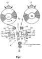
- FIG. 1 shows a left rewinder 11 having a preceding film F1 supported thereon, and a right rewinder 12 disposed in parallel to the rewinder 11 and having supported thereon a film F2 following the film F1.
- the preceding film F1 and the following film F2 are of the same type and made from polyethylene and have a thickness of about 0.5 mm for use as a closure material.
- the rewinders 11, 12 are provided with respective left and right rear end sensors 13, 14.
- left and right guide rollers 15, 16 Arranged below the two rewinders 11, 12 are left and right guide rollers 15, 16 which are horizontally spaced apart from each other. A feed roller 17 and a holding roller 18 are arranged one above another, as positioned below the space between the guide rollers 15, 16.
- a connecting station S is provided between the pair of guide rollers 15, 16 and the pair of feed and holding rollers 17, 18.
- pair of left and right connecting members 21, 22 so as to be movable toward or away from each other, and a pair of cutters 23, 24 which are similarly movable. When these components are moved away, a cutter receiver 25 is movable into or out of the space therebetween.
- the preceding film F1 is guided downward from the left rewinder 11, reeved around the left guide roller 15, passed between the feed roller 17 and the holding roller 18 and thereafter sent to an unillustrated filling machine.
- the following film F2 is guided downward from the right rewinder 12, reeved around the right guide roller 16 and held in a standby position with its leading end guided to the right connecting member 22.
- the first and second vacuum pipes 31, 32 are connected to the outer end of a left support arm 42 extending rightward from a horizontal left movable frame 41 which is L-shaped in cross section.
- the third and fourth vacuum pipes 33, 34 are directed toward the opposite direction to the first and second vacuum pipes 31, 32 transversely of the device (with respect to left-right direction), but identical with the pipes 31, 32 in construction, and attached to a right movable frame 43 by a right support arm 44.
- the left movable frame 41 is attached to the piston rod of a first fluid pressure cylinder 51 which is mounted as directed rightward by unillustrated means.
- the right movable frame 43 is attached to the piston rod of a second fluid pressure cylinder 52 which is directed leftward.
- the left cutter 23 is in the form of a horizontal plate so disposed as to be movable leftward and rightward between the first and second vacuum pipes 31, 32, and is attached by a depending left bracket to the piston rod of a third fluid pressure cylinder 53 mounted as directed rightward on the left movable frame 41.
- the right cutter 24 is in the form of a horizontal plate so disposed as to be movable leftward and rightward between the third and fourth vacuum pipes 33, 34, and is attached by a depending right bracket to the piston rod of a fourth fluid pressure cylinder 54 mounted as directed leftward on the right movable frame 43.
- a left cushion member 61 is affixed to the right side face of each of the first and second vacuum pipes 31, 32.
- a plurality of left suction bores 62 extend straight through the left cushion member 61 and the right side wall of each of the first and second vacuum pipes 31, 32 for the right side face of the left cushion member 61 to provide a left suction face 63.
- a right cushion member 64 is affixed similarly to each of the third and fourth vacuum pipes 33, 34, and right suction bores 65 and a right suction face 66 are formed alike.
- the cutter receiver 25 is in the form of a striplike plate and supported at one end thereof on a horizontal support axis 71 extending transversely of the device and positioned laterally of the cutters.
- the cutter receiver is pivotally movable by unillustrated means between a horizontal posture indicated in a solid line and a vertical posture indicated in a chain line in FIG. 1.
- the cutter receiver 25 has a cutter escape groove 72 formed at the widthwise midportion thereof and extending longitudinally. thereof.
- the films are connected together by the operation to be described below with reference to FIG. 3.
- the preceding film F1 supported by the left rewinder 11 is shown in FIG. 3a while it is being transported.
- the piston rods of the first to fourth fluid pressure cylinders 51 to 54 are all retracted, and the left and right connecting members 21, 22, as well as the cutters 23, 24, are away from each other.
- the cutter receiver 25 is advanced into the space between these opposed components.
- the following film F2 is set on the right rewinder 12 anew.
- a connecting tape T is affixed to the leading end of the following film F2 and fixed to the right connecting member 22 by being attracted thereto by suction. This state is shown in detail in FIG.
- the piston rod of the first fluid pressure cylinder 51 Upon the cessation of transport of the preceding film F1, the piston rod of the first fluid pressure cylinder 51 is advanced to move the left connecting member 21 rightward along with the left cutter 23, pressing the left connecting member 21 against the cutter receiver 25 with the preceding film F1 interposed therebetween.
- the first and second vacuum pipes 31, 32 are actuated to form a vacuum.
- the piston rod of the third fluid pressure cylinder 53 is advanced to move the left cutter 23 further rightward, causing the outer end of the left cutter 23 to project rightward beyond the first and second vacuum pipes 31, 32, whereby the preceding film F1 is cut by the left cutter 23.
- the piston rods of the first and third fluid pressure cylinders 51, 53 are retracted to move the left connecting member 21 leftward with the cut preceding film F1 held attracted thereto as shown in FIG. 3c, and the left cutter 23 is concealed in the left connecting member 21.
- the cutter receiver 25 is pivotally moved upward and retracted from the space between the opposed connecting members 21, 22.
- the first and second fluid pressure cylinders 51, 52 are then actuated to bring the left and right connecting members 21, 22 toward each other as seen in FIG. 3d.
- the connecting members 21, 22 are pressed against each other, the end portion of the preceding film F1 downstream from the cut portion is joined to the extending portion of the connecting tape T, whereby the preceding film F1 and the following film F2 are connected together.
- the second to fourth vacuum pipes 32 to 34 are thereafter brought out of operation to eliminate the vacuum.
- the piston rods of the first and second fluid pressure cylinders 51, 52 are retracted to move the opposed connecting members 21, 22 away from each other as shown in FIG. 3e.
- the cutter receiver 25 is pivotally moved downward and advanced into the space between the connecting members 21, 22 as positioned away from each other.
- the end portion of the preceding film F1 upstream from the cut portion is held attracted to the first vacuum pipe 31 by suction, whereas the preceding film F1 is connected to the following film F2 in a straight form, and the transport of the film F2 is started in this state. In this way, the films are completely connected together.
- FIG. 3f shows a new film F3 as set in place on the left rewinder 11 and made ready for the subsequent connecting operation.
- a connecting film T is affixed to the leading end of the film F3 as previously described and held attracted to the left connecting member 21.
Claims (4)
- Eine Vorrichtung zum Verbinden von Folienrollen mit:Mitteln (11, 12), um eine vorausgehende Folie (F1) und eine Folie (F2), die der vorausgehenden folgt, über eine Verbindungsstation (S) zu transportieren,einem Paar von Verbindungselementen (21, 22), die an der Verbindungsstation (S) angeordnet und aufeinander zu oder voneinander weg bewegbar sind, wobei ein Folientransportweg zwischen ihnen angeordnet ist, wobei jedes der Verbindungselemente eine Fläche (63, 66) hat, die der anderen gegenüberliegt und als Ansaugfläche dient,einem Paar von Schneidvorrichtungen (23, 24), die angeordnet sind, um eine der Folien zu schneiden, wenn die Folien unter Verwendung des Paares von Verbindungselementen verbunden werden, undeinem Schneidvorrichtungsaufnehmer (25), welcher angeordnet ist, um mit dem Paar von Schneidvorrichtungen während des Schneidens zusammenzuwirken, dadurch gekennzeichnet, daßdas Paar von Schneidvorrichtungen (23, 24) derart angeordnet ist, daß es aus den jeweiligen Ansaugflächen (63, 66) der Verbindungselemente (21, 22) heraus oder in diese hinein bewegbar ist, undder Schneidvorrichtungaufnehmer (25) derart angeordnet ist, daß er in den Raum zwischen den Verbindungselementen (21, 22), wenn sie voneinander weg bewegt sind, hinein oder aus ihm heraus bewegbar ist.
- Eine Vorrichtung zum Verbinden von Folienrollen nach Anspruch 1, wobei jedes der Verbindungselemente (21, 22) ein Paar Vakuumrohre (31-32, 33-34) umfaßt, die an jeweils einander gegenüberliegenden Seiten der Schneidvorrichtung (23, 24) angeordnet sind und jeweils Ansaugöffnungen (62, 65) aufweisen, die in ihre Ansaugfläche (63, 65) ausgebildet sind.
- Eine Vorrichtung zum Verbinden von Folienrollen nach Anspruch 1 oder 2, wobei jedes der Verbindungselemente (21, 22) an einem bewegbaren Rahmen (41, 43) zusammen mit der Schneidvorrichtung (23, 24) angebracht ist.
- Eine Vorrichtung zum Verbinden von Folienrollen nach Anspruch 3, wobei ein Fluiddruckzylinder (53, 54) zwischen der Schneidvorrichtung (23, 24) und dem bewegbaren Rahmen (41, 43) vorgesehen ist.
Priority Applications (1)
| Application Number | Priority Date | Filing Date | Title |
|---|---|---|---|
| DK01200627T DK1127821T3 (da) | 2000-02-23 | 2001-02-21 | Indretning og fremgangsmåde til forbindelse af filmruller |
Applications Claiming Priority (2)
| Application Number | Priority Date | Filing Date | Title |
|---|---|---|---|
| JP2000045860 | 2000-02-23 | ||
| JP2000045860A JP2001233514A (ja) | 2000-02-23 | 2000-02-23 | ロールフィルム接続装置およびその方法 |
Publications (3)
| Publication Number | Publication Date |
|---|---|
| EP1127821A2 EP1127821A2 (de) | 2001-08-29 |
| EP1127821A3 EP1127821A3 (de) | 2003-01-08 |
| EP1127821B1 true EP1127821B1 (de) | 2005-05-11 |
Family
ID=18568386
Family Applications (1)
| Application Number | Title | Priority Date | Filing Date |
|---|---|---|---|
| EP01200627A Expired - Lifetime EP1127821B1 (de) | 2000-02-23 | 2001-02-21 | Vorrichtung und Verfahren zum Verbinden von Folienrollen |
Country Status (6)
| Country | Link |
|---|---|
| US (1) | US6500288B2 (de) |
| EP (1) | EP1127821B1 (de) |
| JP (1) | JP2001233514A (de) |
| AT (1) | ATE295324T1 (de) |
| DE (1) | DE60110653T2 (de) |
| DK (1) | DK1127821T3 (de) |
Cited By (1)
| Publication number | Priority date | Publication date | Assignee | Title |
|---|---|---|---|---|
| TWI735685B (zh) * | 2017-02-08 | 2021-08-11 | 日商日東電工股份有限公司 | 黏著帶接合方法及黏著帶接合裝置 |
Families Citing this family (43)
| Publication number | Priority date | Publication date | Assignee | Title |
|---|---|---|---|---|
| EP1277683B1 (de) * | 2001-07-20 | 2006-08-23 | Fameccanica.Data S.p.A. | Verfahren und Vorrichtung zum Aufnehmen von Material |
| US6923880B2 (en) * | 2002-11-19 | 2005-08-02 | Keene Technology Inc., | Film splicer apparatus and method for splicing a film used for bagging snack foods |
| JP4170181B2 (ja) * | 2003-09-09 | 2008-10-22 | リンテック株式会社 | 帯状体の接続装置及び接続方法 |
| DE102004026312A1 (de) * | 2004-05-26 | 2005-12-15 | Krones Ag | Folienspleißstation |
| DE102004032528C5 (de) * | 2004-07-06 | 2012-04-05 | Khs Gmbh | Verfahren zum Durchführen eines Rollenwechsels bei einer Versorgungseinheit zum Zuführen eines bahnartigen Flachmaterials an eine Verpackungsmaschine oder dergleichen Verarbeitungsmaschine sowie Versorgungseinheit zum Durchführen dieses Verfahrens |
| DE102006015477B3 (de) * | 2006-04-03 | 2007-12-20 | Uhlmann Pac-Systeme Gmbh & Co. Kg | Vorrichtung zum Ersetzen einer ersten Materialbahn durch eine zweite Materialbahn |
| ES2324575B1 (es) * | 2007-02-22 | 2010-04-19 | Manuel Torres Martinez | Empalmador de tiras de fibra para maquinas de encintado. |
| IT1393913B1 (it) * | 2009-05-05 | 2012-05-17 | Rent Srl | Gruppo e procedimento di alimentazione di bobine di materiale in foglio, in particolare ma non esclusivamente film plastico stampato con riferimenti di posizione per confezionatrici automatiche |
| DE102010021732A1 (de) * | 2010-05-27 | 2011-12-01 | Krones Ag | Spleißvorrichtung und Verfahren zum Spleißen eines bahnartigen Flachmaterials |
| CN102069605B (zh) * | 2010-10-09 | 2013-01-30 | 杭州珂瑞特机械制造有限公司 | 一次性卫生用品原材料拼接系统及拼接方法 |
| CN102069604B (zh) * | 2010-10-09 | 2014-08-06 | 杭州珂瑞特机械制造有限公司 | 宽幅零速换接料系统及换接料方法 |
| TWI551560B (zh) * | 2010-11-30 | 2016-10-01 | 康寧公司 | 玻璃帶、接合玻璃帶之方法、以及製備用於接合之已塗佈玻璃帶之方法 |
| JP5203497B2 (ja) * | 2011-01-07 | 2013-06-05 | 富士フイルム株式会社 | フィルム同士の熱溶着接合方法及び接合装置並びに光学フィルムの製造方法 |
| KR101804851B1 (ko) | 2011-01-07 | 2017-12-05 | 후지필름 가부시키가이샤 | 필름끼리의 열용착 접합방법과 접합장치, 및 광학 필름의 제조방법 |
| JP5908231B2 (ja) * | 2011-08-22 | 2016-04-26 | 株式会社トパック | 自動包装機の継ぎ装置 |
| JP5943704B2 (ja) * | 2012-05-18 | 2016-07-05 | 富士機械工業株式会社 | ウェブ接続装置 |
| TWI591040B (zh) | 2012-10-22 | 2017-07-11 | 康寧公司 | 玻璃纖維網和拼接的方法 |
| WO2014086891A1 (de) * | 2012-12-04 | 2014-06-12 | Dieffenbacher GmbH Maschinen- und Anlagenbau | Verfahren und system zum zuführen von material zu einem auflegemaschine |
| KR102091229B1 (ko) * | 2013-04-03 | 2020-03-20 | 삼성디스플레이 주식회사 | 표시 패널용 절단 장치 및 이를 이용한 표시 장치의 제조 방법 |
| CN103318458A (zh) * | 2013-07-02 | 2013-09-25 | 江苏科瑞恩自动化科技有限公司 | 一种自动送膜供料机构 |
| CN103318457A (zh) * | 2013-07-02 | 2013-09-25 | 江苏科瑞恩自动化科技有限公司 | 一种自动吸膜机构 |
| US9637340B1 (en) * | 2014-03-26 | 2017-05-02 | Butler Automatic, Inc. | Automatic sleeving splicer |
| CN105198236B (zh) * | 2014-06-26 | 2019-04-02 | 日东电工株式会社 | 光学膜连续供给装置及光学膜连续供给方法 |
| JP6427186B2 (ja) * | 2014-06-30 | 2018-11-21 | 株式会社瑞光 | シート繰出システム及びこれを用いたシート繰出方法 |
| CN104192641A (zh) * | 2014-07-21 | 2014-12-10 | 张晋凯 | 走线过程中的自动换接线方法及装置 |
| CN104192607B (zh) * | 2014-08-12 | 2017-01-25 | 杭州中亚机械股份有限公司 | 一种膜材料交替连续供应装置 |
| CN204162141U (zh) * | 2014-10-10 | 2015-02-18 | 日东电工株式会社 | 光学膜连接装置 |
| CN104692168B (zh) * | 2015-01-16 | 2017-11-07 | 成都印钞有限公司 | 一种防伪膜带双工位开卷和接带装置及其控制方法 |
| JP6533420B2 (ja) * | 2015-06-22 | 2019-06-19 | 株式会社ヒラノテクシード | 吸引装置とそれを用いたウエブの接続装置 |
| CN106395473B (zh) * | 2016-10-15 | 2019-01-25 | 深圳市海目星激光科技有限公司 | 卷料放卷自动换卷接带装置 |
| JP6993827B2 (ja) * | 2017-09-26 | 2022-01-14 | 株式会社京都製作所 | テープ供給装置及び封函装置 |
| CN108861751A (zh) * | 2018-06-04 | 2018-11-23 | 佛山市高明正机械设备有限公司 | 一种多层膜材贴合机 |
| CN109911676A (zh) * | 2019-03-19 | 2019-06-21 | 江苏新美星包装机械股份有限公司 | 一种薄膜卷接料装置 |
| KR102181370B1 (ko) * | 2019-08-01 | 2020-11-23 | 윤중식 | 원단 연결 기능을 구비한 언와인딩 장치 |
| KR102390172B1 (ko) * | 2020-06-03 | 2022-04-25 | 주식회사 탑 엔지니어링 | 연결 장치 및 이를 이용한 연결 방법 |
| TWI759859B (zh) * | 2020-09-14 | 2022-04-01 | 禾廣企業股份有限公司 | 自動接膜設備及使用其之自動接膜方法 |
| EP3967637B1 (de) * | 2020-09-14 | 2023-11-29 | Harro Höfliger Verpackungsmaschinen GmbH | Vorrichtung und verfahren zum spleissen und kontinuierlichen bereitstellen einer folienbahn |
| CN113003261B (zh) * | 2021-04-09 | 2022-09-16 | 广州通泽机械有限公司 | 一种厚基材剪裁双面贴胶接料装置及方法 |
| KR20230106231A (ko) * | 2022-01-06 | 2023-07-13 | 주식회사 엘지에너지솔루션 | 전극 연결 장치 |
| DE102022119211A1 (de) | 2022-08-01 | 2024-02-01 | Körber Technologies Gmbh | Vorrichtung und Verfahren zum Verbinden von endlichen Materialbahnen |
| DE102022119212A1 (de) | 2022-08-01 | 2024-02-01 | Körber Technologies Gmbh | Vorrichtung und Verfahren zum Verbinden von endlichen Materialbahnen |
| DE102022119210A1 (de) | 2022-08-01 | 2024-02-01 | Körber Technologies Gmbh | Vorrichtung und Verfahren zum Verbinden von endlichen Materialbahnen |
| KR102594981B1 (ko) * | 2023-07-21 | 2023-10-27 | 주식회사제이에스텍 | 이차전지 전극 제조공정용 언와인딩 장치 |
Family Cites Families (12)
| Publication number | Priority date | Publication date | Assignee | Title |
|---|---|---|---|---|
| US3440126A (en) * | 1966-02-28 | 1969-04-22 | Eastman Kodak Co | Web splicer |
| US3858819A (en) * | 1972-10-24 | 1975-01-07 | Butler Automatic Inc | Web supply apparatus |
| JPS5311694A (en) | 1976-07-19 | 1978-02-02 | Yoshitsuka Seiki Kk | Automatic continuous film feeder |
| US4190483A (en) * | 1977-03-15 | 1980-02-26 | Compensating Tension Controls, Inc. | Butt splicer |
| US4157934A (en) * | 1977-07-18 | 1979-06-12 | Compensating Tension Controls, Inc. | Low tension lap slicer unit |
| ES484893A0 (es) * | 1979-10-10 | 1980-11-01 | Torres Martinez M | Perfeccionamientos en sistemas de empalme automatico de bandas laminadas o bobinas de papel |
| JPS5859146A (ja) * | 1981-09-30 | 1983-04-08 | Rengo Co Ltd | 紙継ぎ方法及びその装置 |
| JPS5922841A (ja) * | 1982-07-28 | 1984-02-06 | Isowa Fuupaa Suifuto:Kk | ウエブスプライサ− |
| JP2519613B2 (ja) | 1991-05-31 | 1996-07-31 | 株式会社フジキカイ | 包装用フィルムの自動接続装置 |
| IT227176Y1 (it) * | 1992-11-11 | 1997-09-15 | Ocme Srl | Dispositivo per la giunzione di film di materiale plastico termoestraibile in una macchina utilizzante detto film |
| JP2873182B2 (ja) * | 1995-03-17 | 1999-03-24 | ソマール株式会社 | フィルム張付装置における原反フィルムの連続的供給方法及び装置 |
| DE19804614A1 (de) * | 1998-02-06 | 1999-08-12 | Focke & Co | Verfahren und Vorrichtung zum Verbinden von Materialbahnen |
-
2000
- 2000-02-23 JP JP2000045860A patent/JP2001233514A/ja active Pending
-
2001
- 2001-02-21 DK DK01200627T patent/DK1127821T3/da active
- 2001-02-21 DE DE60110653T patent/DE60110653T2/de not_active Expired - Fee Related
- 2001-02-21 US US09/788,549 patent/US6500288B2/en not_active Expired - Fee Related
- 2001-02-21 EP EP01200627A patent/EP1127821B1/de not_active Expired - Lifetime
- 2001-02-21 AT AT01200627T patent/ATE295324T1/de not_active IP Right Cessation
Cited By (1)
| Publication number | Priority date | Publication date | Assignee | Title |
|---|---|---|---|---|
| TWI735685B (zh) * | 2017-02-08 | 2021-08-11 | 日商日東電工股份有限公司 | 黏著帶接合方法及黏著帶接合裝置 |
Also Published As
| Publication number | Publication date |
|---|---|
| JP2001233514A (ja) | 2001-08-28 |
| DK1127821T3 (da) | 2005-07-18 |
| EP1127821A2 (de) | 2001-08-29 |
| EP1127821A3 (de) | 2003-01-08 |
| US20010016120A1 (en) | 2001-08-23 |
| DE60110653T2 (de) | 2005-11-17 |
| DE60110653D1 (de) | 2005-06-16 |
| US6500288B2 (en) | 2002-12-31 |
| ATE295324T1 (de) | 2005-05-15 |
Similar Documents
| Publication | Publication Date | Title |
|---|---|---|
| EP1127821B1 (de) | Vorrichtung und Verfahren zum Verbinden von Folienrollen | |
| US6192955B1 (en) | Apparatus and method for aligning webs | |
| EP0472245B1 (de) | Gerät zum fortlaufenden Abspulen einer Mehrzahl aufgerollter Bänder | |
| US4785698A (en) | Separating device for plates | |
| EP2933211B1 (de) | Verfahren und systeme zum bearbeiten von filmen in verpackungsmaschinen | |
| EP0847948B1 (de) | Vorrichtung zum Verbinden von Filmen | |
| EP0426931B1 (de) | Verfahren zum Aufbringen eines Films und Vorrichtung zur Ausführung desselben | |
| JP4964228B2 (ja) | 2本の平形チューブ状ウェブの端部を接合する装置および方法 | |
| JP5181456B2 (ja) | 製袋装置及び袋の製造方法 | |
| US5248374A (en) | Strip winder for a tire building machine | |
| EP0842882B1 (de) | Methode und Vorrichtung zum Verbinden einer Bahn | |
| JP2519613B2 (ja) | 包装用フィルムの自動接続装置 | |
| JPH08118514A (ja) | 帯状部材の成形方法および装置 | |
| EP1013583A3 (de) | Automatischer Spleisser für Abwickler | |
| JP4377371B2 (ja) | フィルム材の接合装置 | |
| JPS6319356Y2 (de) | ||
| JP2017165524A (ja) | シート接続装置 | |
| JP3349171B2 (ja) | ラミネート枚葉紙のカッター構造 | |
| JP3856930B2 (ja) | 感光材料への遮光材料装着方法およびその装置 | |
| JP4167003B2 (ja) | 加硫済トレッド部材の切断方法 | |
| JP2000255517A (ja) | 封緘装置 | |
| JPH0647844A (ja) | 軟質フィルムからの扁平包装袋の作成装置 | |
| JPH06171067A (ja) | 印刷機の給紙装置 | |
| JP2003191917A (ja) | 充填機 | |
| JPH10279149A (ja) | 継ぎ合わせのずれの調節方法 |
Legal Events
| Date | Code | Title | Description |
|---|---|---|---|
| PUAI | Public reference made under article 153(3) epc to a published international application that has entered the european phase |
Free format text: ORIGINAL CODE: 0009012 |
|
| AK | Designated contracting states |
Kind code of ref document: A2 Designated state(s): AT BE CH CY DE DK ES FI FR GB GR IE IT LI LU MC NL PT SE TR |
|
| AX | Request for extension of the european patent |
Free format text: AL;LT;LV;MK;RO;SI |
|
| PUAL | Search report despatched |
Free format text: ORIGINAL CODE: 0009013 |
|
| AK | Designated contracting states |
Kind code of ref document: A3 Designated state(s): AT BE CH CY DE DK ES FI FR GB GR IE IT LI LU MC NL PT SE TR |
|
| AX | Request for extension of the european patent |
Free format text: AL;LT;LV;MK;RO;SI |
|
| 17P | Request for examination filed |
Effective date: 20030415 |
|
| 17Q | First examination report despatched |
Effective date: 20030704 |
|
| AKX | Designation fees paid |
Designated state(s): AT BE CH CY DE DK ES FI FR GB GR IE IT LI LU MC NL PT SE TR |
|
| GRAP | Despatch of communication of intention to grant a patent |
Free format text: ORIGINAL CODE: EPIDOSNIGR1 |
|
| GRAS | Grant fee paid |
Free format text: ORIGINAL CODE: EPIDOSNIGR3 |
|
| GRAA | (expected) grant |
Free format text: ORIGINAL CODE: 0009210 |
|
| AK | Designated contracting states |
Kind code of ref document: B1 Designated state(s): AT BE CH CY DE DK ES FI FR GB GR IE IT LI LU MC NL PT SE TR |
|
| PG25 | Lapsed in a contracting state [announced via postgrant information from national office to epo] |
Ref country code: IT Free format text: LAPSE BECAUSE OF FAILURE TO SUBMIT A TRANSLATION OF THE DESCRIPTION OR TO PAY THE FEE WITHIN THE PRESCRIBED TIME-LIMIT;WARNING: LAPSES OF ITALIAN PATENTS WITH EFFECTIVE DATE BEFORE 2007 MAY HAVE OCCURRED AT ANY TIME BEFORE 2007. THE CORRECT EFFECTIVE DATE MAY BE DIFFERENT FROM THE ONE RECORDED. Effective date: 20050511 Ref country code: AT Free format text: LAPSE BECAUSE OF FAILURE TO SUBMIT A TRANSLATION OF THE DESCRIPTION OR TO PAY THE FEE WITHIN THE PRESCRIBED TIME-LIMIT Effective date: 20050511 Ref country code: BE Free format text: LAPSE BECAUSE OF FAILURE TO SUBMIT A TRANSLATION OF THE DESCRIPTION OR TO PAY THE FEE WITHIN THE PRESCRIBED TIME-LIMIT Effective date: 20050511 Ref country code: FI Free format text: LAPSE BECAUSE OF FAILURE TO SUBMIT A TRANSLATION OF THE DESCRIPTION OR TO PAY THE FEE WITHIN THE PRESCRIBED TIME-LIMIT Effective date: 20050511 |
|
| REG | Reference to a national code |
Ref country code: GB Ref legal event code: FG4D |
|
| REG | Reference to a national code |
Ref country code: CH Ref legal event code: EP |
|
| REG | Reference to a national code |
Ref country code: SE Ref legal event code: TRGR |
|
| REG | Reference to a national code |
Ref country code: CH Ref legal event code: NV Representative=s name: PATENTANWALTSBUERO JEAN HUNZIKER Ref country code: IE Ref legal event code: FG4D |
|
| REF | Corresponds to: |
Ref document number: 60110653 Country of ref document: DE Date of ref document: 20050616 Kind code of ref document: P |
|
| REG | Reference to a national code |
Ref country code: DK Ref legal event code: T3 |
|
| PG25 | Lapsed in a contracting state [announced via postgrant information from national office to epo] |
Ref country code: GR Free format text: LAPSE BECAUSE OF FAILURE TO SUBMIT A TRANSLATION OF THE DESCRIPTION OR TO PAY THE FEE WITHIN THE PRESCRIBED TIME-LIMIT Effective date: 20050811 |
|
| PG25 | Lapsed in a contracting state [announced via postgrant information from national office to epo] |
Ref country code: PT Free format text: LAPSE BECAUSE OF FAILURE TO SUBMIT A TRANSLATION OF THE DESCRIPTION OR TO PAY THE FEE WITHIN THE PRESCRIBED TIME-LIMIT Effective date: 20051019 |
|
| PG25 | Lapsed in a contracting state [announced via postgrant information from national office to epo] |
Ref country code: GB Free format text: LAPSE BECAUSE OF NON-PAYMENT OF DUE FEES Effective date: 20060221 Ref country code: IE Free format text: LAPSE BECAUSE OF NON-PAYMENT OF DUE FEES Effective date: 20060221 |
|
| PG25 | Lapsed in a contracting state [announced via postgrant information from national office to epo] |
Ref country code: SE Free format text: LAPSE BECAUSE OF NON-PAYMENT OF DUE FEES Effective date: 20060222 |
|
| PG25 | Lapsed in a contracting state [announced via postgrant information from national office to epo] |
Ref country code: LI Free format text: LAPSE BECAUSE OF NON-PAYMENT OF DUE FEES Effective date: 20060228 Ref country code: LU Free format text: LAPSE BECAUSE OF NON-PAYMENT OF DUE FEES Effective date: 20060228 Ref country code: CH Free format text: LAPSE BECAUSE OF NON-PAYMENT OF DUE FEES Effective date: 20060228 Ref country code: DK Free format text: LAPSE BECAUSE OF NON-PAYMENT OF DUE FEES Effective date: 20060228 Ref country code: MC Free format text: LAPSE BECAUSE OF NON-PAYMENT OF DUE FEES Effective date: 20060228 |
|
| PLBE | No opposition filed within time limit |
Free format text: ORIGINAL CODE: 0009261 |
|
| STAA | Information on the status of an ep patent application or granted ep patent |
Free format text: STATUS: NO OPPOSITION FILED WITHIN TIME LIMIT |
|
| ET | Fr: translation filed | ||
| 26N | No opposition filed |
Effective date: 20060214 |
|
| PG25 | Lapsed in a contracting state [announced via postgrant information from national office to epo] |
Ref country code: DE Free format text: LAPSE BECAUSE OF NON-PAYMENT OF DUE FEES Effective date: 20060901 Ref country code: NL Free format text: LAPSE BECAUSE OF NON-PAYMENT OF DUE FEES Effective date: 20060901 |
|
| REG | Reference to a national code |
Ref country code: DK Ref legal event code: EBP |
|
| REG | Reference to a national code |
Ref country code: CH Ref legal event code: PL |
|
| EUG | Se: european patent has lapsed | ||
| GBPC | Gb: european patent ceased through non-payment of renewal fee |
Effective date: 20060221 |
|
| NLV4 | Nl: lapsed or anulled due to non-payment of the annual fee |
Effective date: 20060901 |
|
| REG | Reference to a national code |
Ref country code: IE Ref legal event code: MM4A |
|
| REG | Reference to a national code |
Ref country code: FR Ref legal event code: ST Effective date: 20061031 |
|
| PG25 | Lapsed in a contracting state [announced via postgrant information from national office to epo] |
Ref country code: FR Free format text: LAPSE BECAUSE OF NON-PAYMENT OF DUE FEES Effective date: 20060228 |
|
| PG25 | Lapsed in a contracting state [announced via postgrant information from national office to epo] |
Ref country code: TR Free format text: LAPSE BECAUSE OF FAILURE TO SUBMIT A TRANSLATION OF THE DESCRIPTION OR TO PAY THE FEE WITHIN THE PRESCRIBED TIME-LIMIT Effective date: 20050511 |
|
| PG25 | Lapsed in a contracting state [announced via postgrant information from national office to epo] |
Ref country code: CY Free format text: LAPSE BECAUSE OF FAILURE TO SUBMIT A TRANSLATION OF THE DESCRIPTION OR TO PAY THE FEE WITHIN THE PRESCRIBED TIME-LIMIT Effective date: 20050511 |
|
| PG25 | Lapsed in a contracting state [announced via postgrant information from national office to epo] |
Ref country code: ES Free format text: LAPSE BECAUSE OF NON-PAYMENT OF DUE FEES Effective date: 20060228 |