EP1127800A2 - Kappe für Schlauchbeutel - Google Patents
Kappe für Schlauchbeutel Download PDFInfo
- Publication number
- EP1127800A2 EP1127800A2 EP01810157A EP01810157A EP1127800A2 EP 1127800 A2 EP1127800 A2 EP 1127800A2 EP 01810157 A EP01810157 A EP 01810157A EP 01810157 A EP01810157 A EP 01810157A EP 1127800 A2 EP1127800 A2 EP 1127800A2
- Authority
- EP
- European Patent Office
- Prior art keywords
- tubular bag
- braid
- receiving means
- bag according
- liquid
- Prior art date
- Legal status (The legal status is an assumption and is not a legal conclusion. Google has not performed a legal analysis and makes no representation as to the accuracy of the status listed.)
- Withdrawn
Links
- 239000007788 liquid Substances 0.000 claims abstract description 23
- 239000000463 material Substances 0.000 claims abstract description 15
- 239000002250 absorbent Substances 0.000 claims description 13
- 230000002745 absorbent Effects 0.000 claims description 13
- 239000000126 substance Substances 0.000 claims description 10
- 229920002125 Sokalan® Polymers 0.000 claims description 2
- 239000004744 fabric Substances 0.000 claims description 2
- 239000004584 polyacrylic acid Substances 0.000 claims description 2
- 239000000945 filler Substances 0.000 description 3
- 238000004519 manufacturing process Methods 0.000 description 3
- 239000000565 sealant Substances 0.000 description 3
- 239000000243 solution Substances 0.000 description 3
- 230000001070 adhesive effect Effects 0.000 description 2
- 239000003795 chemical substances by application Substances 0.000 description 2
- 150000001875 compounds Chemical class 0.000 description 2
- 230000000694 effects Effects 0.000 description 2
- 241000255925 Diptera Species 0.000 description 1
- 239000000853 adhesive Substances 0.000 description 1
- 239000006227 byproduct Substances 0.000 description 1
- 238000011109 contamination Methods 0.000 description 1
- 125000003700 epoxy group Chemical group 0.000 description 1
- 230000009969 flowable effect Effects 0.000 description 1
- 239000003292 glue Substances 0.000 description 1
- 238000003384 imaging method Methods 0.000 description 1
- 238000002347 injection Methods 0.000 description 1
- 239000007924 injection Substances 0.000 description 1
- 239000002184 metal Substances 0.000 description 1
- 238000000034 method Methods 0.000 description 1
- 239000000203 mixture Substances 0.000 description 1
- 239000004570 mortar (masonry) Substances 0.000 description 1
- 229920000058 polyacrylate Polymers 0.000 description 1
- 229920001296 polysiloxane Polymers 0.000 description 1
- 229920002635 polyurethane Polymers 0.000 description 1
- 239000004814 polyurethane Substances 0.000 description 1
- 238000007789 sealing Methods 0.000 description 1
- 239000007787 solid Substances 0.000 description 1
- 238000003466 welding Methods 0.000 description 1
Images
Classifications
-
- B—PERFORMING OPERATIONS; TRANSPORTING
- B65—CONVEYING; PACKING; STORING; HANDLING THIN OR FILAMENTARY MATERIAL
- B65D—CONTAINERS FOR STORAGE OR TRANSPORT OF ARTICLES OR MATERIALS, e.g. BAGS, BARRELS, BOTTLES, BOXES, CANS, CARTONS, CRATES, DRUMS, JARS, TANKS, HOPPERS, FORWARDING CONTAINERS; ACCESSORIES, CLOSURES, OR FITTINGS THEREFOR; PACKAGING ELEMENTS; PACKAGES
- B65D81/00—Containers, packaging elements, or packages, for contents presenting particular transport or storage problems, or adapted to be used for non-packaging purposes after removal of contents
- B65D81/24—Adaptations for preventing deterioration or decay of contents; Applications to the container or packaging material of food preservatives, fungicides, pesticides or animal repellants
- B65D81/26—Adaptations for preventing deterioration or decay of contents; Applications to the container or packaging material of food preservatives, fungicides, pesticides or animal repellants with provision for draining away, or absorbing, or removing by ventilation, fluids, e.g. exuded by contents; Applications of corrosion inhibitors or desiccators
- B65D81/264—Adaptations for preventing deterioration or decay of contents; Applications to the container or packaging material of food preservatives, fungicides, pesticides or animal repellants with provision for draining away, or absorbing, or removing by ventilation, fluids, e.g. exuded by contents; Applications of corrosion inhibitors or desiccators for absorbing liquids
-
- B—PERFORMING OPERATIONS; TRANSPORTING
- B65—CONVEYING; PACKING; STORING; HANDLING THIN OR FILAMENTARY MATERIAL
- B65D—CONTAINERS FOR STORAGE OR TRANSPORT OF ARTICLES OR MATERIALS, e.g. BAGS, BARRELS, BOTTLES, BOXES, CANS, CARTONS, CRATES, DRUMS, JARS, TANKS, HOPPERS, FORWARDING CONTAINERS; ACCESSORIES, CLOSURES, OR FITTINGS THEREFOR; PACKAGING ELEMENTS; PACKAGES
- B65D33/00—Details of, or accessories for, sacks or bags
- B65D33/16—End- or aperture-closing arrangements or devices
- B65D33/1616—Elements constricting the neck of the bag
- B65D33/1641—Staples, clips or clamps made of metal
Definitions
- the invention relates to a tubular bag for one- or two-component compositions, which at least has one end gathered into a braid, the braid with a Clip is closed.
- Methods are known which are carried out by additional measures such as welding or should lead to the tubular bags being sealed by additional sealants.
- Tubular bags of the type mentioned are known for example from DE 29809514 U1
- the Tubular bag has a sealing film in the area of the braid, consisting of, for example Wax, glue or the like.
- a disadvantage of this known solution is, however, that the leakage of the liquid in the area of the braid is not stopped, because the sealants generally have no adhesive effect on the surface of the tubular bag to reach.
- the present invention has for its object in tubular bags with at least an end gathered into a braid an uncontrolled emergence of the in the Avoid liquid contained in tubular bags.
- the object is achieved in that at least in the area of the braid partially a liquid receiving means is arranged.
- the braid expediently points at least partially on the inner circumference of the tubular bag a liquid absorbent to attach to the gathered end of the tubular bag absorb any escaping liquid immediately.
- the receiving means is also the possibility of the receiving means to be arranged in the free end itself, thus preventing it from external influences is largely protected.
- the braid advantageously points at least partially on the outer circumference of the tubular bag a liquid absorbent. This arrangement makes it an uncontrolled one Leakage of the liquid along the outer circumference of the tubular bag in the Avoided area of the braid.
- the receiving means is preferably arranged at the free end of the braid. Consequently the liquid emerging from the tubular bag can be absorbed at the free end of the braid become. At the front end of the braid, the receiving means can be manufactured easy to attach and this makes production economical. Furthermore, for this Embodiment requires little recording material.
- the receiving means is expediently cap-shaped and comprises the Braid at least partially radially and on the front.
- This one-piece and easy to manufacture Absorbent is an optimal solution, liquid coming from any area of the body Pigtail emerges, and thus the area surrounding the pigtail is free from the Keep liquid.
- the receiving means is advantageously both on the inside of the braid arranged on the end face and radially encompassing cover. This is the recording material protected from external influences.
- the receiving means is preferably formed from an absorbent material. So it is possible to produce the recording material from material easily attachable to the tubular bag. Known from other applications, in particular, can be used as the recording material absorbent, materials are used.
- the absorbent material is an absorbent flow, in particular felt, is the Tubular bags can be manufactured economically and are easy to use for the user.
- the absorbent made of a chemical that reacts with the emerging liquid Substance, the absorbed liquid is chemically bound and a load on the Environment prevented.
- the chemical substance should be chosen so that after the reaction with the liquid is a no longer flowable substance, in particular solid or a highly viscous Fabric arises. Especially in the case of aggressive and / or unpleasant handling This embodiment is ideal for liquids.
- the chemically reacting substance is preferably polyacrylic acid copolymers or polyacrylates provided with epoxy groups for the recording material, making an economical Production of the tubular bag is ensured.
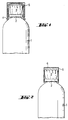
- the tubular bag 1 according to the invention shown in FIGS. 1 and 2 has a metal clip 2 closed, so that a braid 3 is created.
- a receiving means intended in the area of the plait 3 .
- the receiving means is cap-shaped and includes the Braid radial and frontal over its entire circumference.
- the receiving means is formed from a cap made of an absorbent flow 4.
- the embodiment shown in Fig. 2 uses one with the emerging liquid chemically reacting substance 6 as a receiving agent.
- the plait 3 is arranged both frontally and radially encompassing cover 5, like this shows both the variant of FIG. 1 and the variant of FIG. 2.
Landscapes
- Engineering & Computer Science (AREA)
- Mechanical Engineering (AREA)
- Food Science & Technology (AREA)
- Packages (AREA)
- Physical Or Chemical Processes And Apparatus (AREA)
- Bag Frames (AREA)
- External Artificial Organs (AREA)
Abstract
Description
- Fig. 1
- einen teilweise dargestellten Schlauchbeutel mit einem kappenförmigen Aufnahmemittel aus Fliess
- Fig. 2
- einen teilweise dargestellten Schlauchbeutel mit einem chemischen Aufnahmemittel
Claims (10)
- Schlauchbeutel (1) für Ein- oder Zweikomponentenmassen, der mindestens ein Ende aufweist, das zu einem Zopf (3) zusammengerafft ist, wobei der Zopf (3) mit einem Klipp (2) verschlossen ist, dadurch gekennzeichnet, dass im Bereich des Zopfes (3) ein Aufnahmemittel für Flüssigkeit angeordnet ist.
- Schlauchbeutel nach Anspruch 1, dadurch gekennzeichnet, dass das Aufnahmemittel am inneren Umfang des Zopfes (3) angeordnet ist.
- Schlauchbeutel nach Anspruch 1, dadurch gekennzeichnet, dass das Aufnahmemittel am äusseren Umfang des Zopfes (3) angeordnet ist.
- Schlauchbeutel nach Anspruch 3, dadurch gekennzeichnet, dass das Aufnahmemittel am freien Stirnende des Zopfes (3) angeordnet ist.
- Schlauchbeutel nach Anspruch 3, dadurch gekennzeichnet, dass das Aufnahmemittel kappenförmig ausgebildet ist und den Zopf (3) zumindest teilweise radial und stirnseitig umfasst.
- Schlauchbeutel nach einem der Ansprüche 3 bis 5, dadurch gekennzeichnet, dass das Aufnahmemittel auf der Innenseite eines den Zopf (3) sowohl stirnseitig als auch radial umfassenden Deckels (5) angeordnet ist.
- Schlauchbeutel nach einem der Ansprüche 1 bis 6, dadurch gekennzeichnet, dass das Aufnahmemittel aus einem saugfähigen Material gebildet ist.
- Schlauchbeutel nach Anspruch 7, dadurch gekennzeichnet, dass das saugfähige Material ein saugfähiger Fliess (4), insbesondere Filz ist.
- Schlauchbeutel nach einem der Ansprüche 1 bis 6, dadurch gekennzeichnet, dass das Aufnahmemittel aus einem mit der austretenden Flüssigkeit chemischen reagierenden Stoff (6) ist.
- Schlauchbeutel nach Anspruch 9, dadurch gekennzeichnet, dass als chemisch reagierende Stoffe (6) Polyacrylsäure-Copolymere vorgesehen sind.
Applications Claiming Priority (2)
| Application Number | Priority Date | Filing Date | Title |
|---|---|---|---|
| DE10009265A DE10009265A1 (de) | 2000-02-26 | 2000-02-26 | Kappe für Schlauchbeutel |
| DE10009265 | 2000-02-26 |
Publications (2)
| Publication Number | Publication Date |
|---|---|
| EP1127800A2 true EP1127800A2 (de) | 2001-08-29 |
| EP1127800A3 EP1127800A3 (de) | 2003-11-19 |
Family
ID=7632646
Family Applications (1)
| Application Number | Title | Priority Date | Filing Date |
|---|---|---|---|
| EP01810157A Withdrawn EP1127800A3 (de) | 2000-02-26 | 2001-02-16 | Kappe für Schlauchbeutel |
Country Status (3)
| Country | Link |
|---|---|
| US (1) | US6540400B2 (de) |
| EP (1) | EP1127800A3 (de) |
| DE (1) | DE10009265A1 (de) |
Cited By (2)
| Publication number | Priority date | Publication date | Assignee | Title |
|---|---|---|---|---|
| EP1657173A2 (de) | 2004-11-15 | 2006-05-17 | HILTI Aktiengesellschaft | Verschlussanordnung |
| CN103072740A (zh) * | 2013-02-04 | 2013-05-01 | 广东省潮州市质量计量监督检测所 | 一种软包装袋 |
Families Citing this family (4)
| Publication number | Priority date | Publication date | Assignee | Title |
|---|---|---|---|---|
| USD486224S1 (en) | 2002-11-22 | 2004-02-03 | Pbm Plastics, Inc. | Breast pump adapter |
| USD486225S1 (en) | 2002-11-22 | 2004-02-03 | Pbm Plastics, Inc. | Breast pump adapter |
| US20040122356A1 (en) * | 2002-12-23 | 2004-06-24 | Burke Adam P. | Kits and methods for the collection, storage and/or feeding of breast milk |
| US6813814B1 (en) | 2003-02-13 | 2004-11-09 | Grschultz Consultanting, Llc | Clip apparatus |
Citations (2)
| Publication number | Priority date | Publication date | Assignee | Title |
|---|---|---|---|---|
| CH277854A (de) | 1949-11-24 | 1951-09-15 | Schuepbach & Co Ag In Burgdorf | Verfahren zum Herstellen eines Verschlusses an einem Beutel aus Kunststoffolie und nach diesem Verfahren hergestellter Verschluss. |
| DE29809514U1 (de) | 1998-05-27 | 1999-09-30 | fischerwerke Artur Fischer GmbH & Co. KG, 72178 Waldachtal | Verschluß für Schlauchbeutel mit Zweikomponentenmassen |
Family Cites Families (10)
| Publication number | Priority date | Publication date | Assignee | Title |
|---|---|---|---|---|
| DE440472C (de) * | 1925-05-05 | 1927-02-04 | Alfred Johann Auspitzer Dipl I | Schutzhuelle fuer Behaelterverschluesse |
| US1917454A (en) * | 1931-11-11 | 1933-07-11 | Mazzola Lincoln Charles | Moisture take-up for jellies and conserves |
| US2102702A (en) * | 1937-01-28 | 1937-12-21 | Andrew M Hall | Package |
| US2682903A (en) * | 1951-11-30 | 1954-07-06 | Ici Ltd | Closure for containers |
| US3317119A (en) * | 1962-01-31 | 1967-05-02 | Grace W R & Co | Closures for packages |
| US3308936A (en) * | 1964-02-27 | 1967-03-14 | Nebraska Packing Co | Closed end film package |
| US3612325A (en) * | 1968-06-19 | 1971-10-12 | Dover Molded Products Co | Plastic screwcap with rotatable washer |
| DE4019937A1 (de) * | 1990-06-22 | 1992-01-09 | Niedecker Herbert | Dichtungsanordnung am endseitigen verschlussabschnitt einer schlauch- oder beutelpackung aus folienmaterial |
| JPH04339772A (ja) * | 1991-05-09 | 1992-11-26 | Toyo Seikan Kaisha Ltd | ライナー付容器蓋及びその製造方法 |
| DE4312192A1 (de) * | 1993-04-14 | 1994-10-20 | Hilti Ag | Schlauchbeutel aus Verbundfolie |
-
2000
- 2000-02-26 DE DE10009265A patent/DE10009265A1/de not_active Withdrawn
-
2001
- 2001-02-16 EP EP01810157A patent/EP1127800A3/de not_active Withdrawn
- 2001-02-23 US US09/792,441 patent/US6540400B2/en not_active Expired - Lifetime
Patent Citations (2)
| Publication number | Priority date | Publication date | Assignee | Title |
|---|---|---|---|---|
| CH277854A (de) | 1949-11-24 | 1951-09-15 | Schuepbach & Co Ag In Burgdorf | Verfahren zum Herstellen eines Verschlusses an einem Beutel aus Kunststoffolie und nach diesem Verfahren hergestellter Verschluss. |
| DE29809514U1 (de) | 1998-05-27 | 1999-09-30 | fischerwerke Artur Fischer GmbH & Co. KG, 72178 Waldachtal | Verschluß für Schlauchbeutel mit Zweikomponentenmassen |
Cited By (3)
| Publication number | Priority date | Publication date | Assignee | Title |
|---|---|---|---|---|
| EP1657173A2 (de) | 2004-11-15 | 2006-05-17 | HILTI Aktiengesellschaft | Verschlussanordnung |
| EP1657173A3 (de) * | 2004-11-15 | 2008-01-30 | HILTI Aktiengesellschaft | Verschlussanordnung |
| CN103072740A (zh) * | 2013-02-04 | 2013-05-01 | 广东省潮州市质量计量监督检测所 | 一种软包装袋 |
Also Published As
| Publication number | Publication date |
|---|---|
| US6540400B2 (en) | 2003-04-01 |
| EP1127800A3 (de) | 2003-11-19 |
| US20010017948A1 (en) | 2001-08-30 |
| DE10009265A1 (de) | 2001-08-30 |
Similar Documents
| Publication | Publication Date | Title |
|---|---|---|
| EP0663348B1 (de) | Vorrichtung zum Entleeren eines Schlauchbeutels | |
| EP2768619B1 (de) | Mehrkomponentenkartusche | |
| DE29706235U1 (de) | Anordnung zum Ausgeben einer gemischten dentaltechnischen Mehrkomponentenmasse | |
| DE8915525U1 (de) | Injektionsschlauch für abzudichtende Fugen in Betonbauwerken | |
| EP3405293A1 (de) | Auspressvorrichtung für ein foliengebinde, foliengebinde sowie baugruppe aus einer auspressvorrichtung und einem foliengebinde | |
| DE10009265A1 (de) | Kappe für Schlauchbeutel | |
| DE1953736A1 (de) | Dichtungsmittelspritzpatrone | |
| EP0151751B1 (de) | Zylindrischer Behälter | |
| DE69831135T2 (de) | Ausgabegerät fur dynamischen mixer | |
| CH684082A5 (de) | Behälter. | |
| CH632146A5 (de) | Behaelter fuer die aufnahme von miteinander reagierenden substanzen zur herstellung von zaehfluessigen medizinischen bzw. dentalmedizinischen praeparaten. | |
| EP1932775A2 (de) | Abgabeventil mit Beutel | |
| DE9100054U1 (de) | Vorratspackung für zweikomponentiges Polyurethanmaterial | |
| WO1991007333A1 (de) | Folienkartuschen für eine oder zwei komponenten zum einsetzen in dauerkartuschen für kittpistolen | |
| DE102012012360A1 (de) | Vorrichtung zum Auftragen einer pastösen Masse | |
| DE202006014087U1 (de) | Vorrichtung zum Ausbringen und Anmischen von Mehrkomponentenmassen | |
| DE19727369A1 (de) | Rohrförmiges Filterelement | |
| DE9004068U1 (de) | Vorrichtung zum Auftragen von flüssigem oder pastösem Gut, insbesondere Wimperntusche | |
| DE4105658A1 (de) | Geraet zum auftragen von fluessigkeiten | |
| DE20013272U1 (de) | Zweikomponentenspender | |
| DE3047313A1 (de) | Geraet zum verfuellen von bohrloechern | |
| DE102005037890A1 (de) | Vorrichtung zum Aufbewahren und Anwenden eines flüssigen Dentalmaterials | |
| DE2454832A1 (de) | Einrichtung zum befestigen eines mundstuecks an einem behaelter | |
| EP0658381B1 (de) | Auspresswerkzeug für in Kartuschen befindlichen Massen | |
| DE7241635U (de) |
Legal Events
| Date | Code | Title | Description |
|---|---|---|---|
| PUAI | Public reference made under article 153(3) epc to a published international application that has entered the european phase |
Free format text: ORIGINAL CODE: 0009012 |
|
| AK | Designated contracting states |
Kind code of ref document: A2 Designated state(s): AT BE CH CY DE DK ES FI FR GB GR IE IT LI LU MC NL PT SE TR |
|
| AX | Request for extension of the european patent |
Free format text: AL;LT;LV;MK;RO;SI |
|
| PUAL | Search report despatched |
Free format text: ORIGINAL CODE: 0009013 |
|
| AK | Designated contracting states |
Kind code of ref document: A3 Designated state(s): AT BE CH CY DE DK ES FI FR GB GR IE IT LI LU MC NL PT SE TR |
|
| AX | Request for extension of the european patent |
Extension state: AL LT LV MK RO SI |
|
| RIC1 | Information provided on ipc code assigned before grant |
Ipc: 7B 65D 51/00 B Ipc: 7B 65D 51/24 B Ipc: 7B 65D 77/18 B Ipc: 7B 65D 81/26 B Ipc: 7B 65D 33/16 A |
|
| 17P | Request for examination filed |
Effective date: 20040519 |
|
| AKX | Designation fees paid |
Designated state(s): DE FR GB |
|
| 17Q | First examination report despatched |
Effective date: 20040909 |
|
| STAA | Information on the status of an ep patent application or granted ep patent |
Free format text: STATUS: THE APPLICATION IS DEEMED TO BE WITHDRAWN |
|
| 18D | Application deemed to be withdrawn |
Effective date: 20050611 |