EP1127754A1 - Gassackmodulabdeckkappe mit Heizmittel - Google Patents
Gassackmodulabdeckkappe mit Heizmittel Download PDFInfo
- Publication number
- EP1127754A1 EP1127754A1 EP01101669A EP01101669A EP1127754A1 EP 1127754 A1 EP1127754 A1 EP 1127754A1 EP 01101669 A EP01101669 A EP 01101669A EP 01101669 A EP01101669 A EP 01101669A EP 1127754 A1 EP1127754 A1 EP 1127754A1
- Authority
- EP
- European Patent Office
- Prior art keywords
- cover cap
- heating means
- heating
- cover
- cap
- Prior art date
- Legal status (The legal status is an assumption and is not a legal conclusion. Google has not performed a legal analysis and makes no representation as to the accuracy of the status listed.)
- Granted
Links
Images



Classifications
-
- H—ELECTRICITY
- H05—ELECTRIC TECHNIQUES NOT OTHERWISE PROVIDED FOR
- H05B—ELECTRIC HEATING; ELECTRIC LIGHT SOURCES NOT OTHERWISE PROVIDED FOR; CIRCUIT ARRANGEMENTS FOR ELECTRIC LIGHT SOURCES, IN GENERAL
- H05B3/00—Ohmic-resistance heating
-
- B—PERFORMING OPERATIONS; TRANSPORTING
- B60—VEHICLES IN GENERAL
- B60R—VEHICLES, VEHICLE FITTINGS, OR VEHICLE PARTS, NOT OTHERWISE PROVIDED FOR
- B60R21/00—Arrangements or fittings on vehicles for protecting or preventing injuries to occupants or pedestrians in case of accidents or other traffic risks
- B60R21/02—Occupant safety arrangements or fittings, e.g. crash pads
- B60R21/16—Inflatable occupant restraints or confinements designed to inflate upon impact or impending impact, e.g. air bags
- B60R21/20—Arrangements for storing inflatable members in their non-use or deflated condition; Arrangement or mounting of air bag modules or components
- B60R21/215—Arrangements for storing inflatable members in their non-use or deflated condition; Arrangement or mounting of air bag modules or components characterised by the covers for the inflatable member
- B60R21/2165—Arrangements for storing inflatable members in their non-use or deflated condition; Arrangement or mounting of air bag modules or components characterised by the covers for the inflatable member characterised by a tear line for defining a deployment opening
-
- H—ELECTRICITY
- H05—ELECTRIC TECHNIQUES NOT OTHERWISE PROVIDED FOR
- H05B—ELECTRIC HEATING; ELECTRIC LIGHT SOURCES NOT OTHERWISE PROVIDED FOR; CIRCUIT ARRANGEMENTS FOR ELECTRIC LIGHT SOURCES, IN GENERAL
- H05B3/00—Ohmic-resistance heating
- H05B3/10—Heating elements characterised by the composition or nature of the materials or by the arrangement of the conductor
- H05B3/12—Heating elements characterised by the composition or nature of the materials or by the arrangement of the conductor characterised by the composition or nature of the conductive material
- H05B3/14—Heating elements characterised by the composition or nature of the materials or by the arrangement of the conductor characterised by the composition or nature of the conductive material the material being non-metallic
- H05B3/146—Conductive polymers, e.g. polyethylene, thermoplastics
-
- H—ELECTRICITY
- H05—ELECTRIC TECHNIQUES NOT OTHERWISE PROVIDED FOR
- H05B—ELECTRIC HEATING; ELECTRIC LIGHT SOURCES NOT OTHERWISE PROVIDED FOR; CIRCUIT ARRANGEMENTS FOR ELECTRIC LIGHT SOURCES, IN GENERAL
- H05B3/00—Ohmic-resistance heating
- H05B3/20—Heating elements having extended surface area substantially in a two-dimensional [2D] plane, e.g. plate-heater
- H05B3/34—Heating elements having extended surface area substantially in a two-dimensional [2D] plane, e.g. plate-heater flexible, e.g. heating nets or webs
-
- B—PERFORMING OPERATIONS; TRANSPORTING
- B60—VEHICLES IN GENERAL
- B60R—VEHICLES, VEHICLE FITTINGS, OR VEHICLE PARTS, NOT OTHERWISE PROVIDED FOR
- B60R21/00—Arrangements or fittings on vehicles for protecting or preventing injuries to occupants or pedestrians in case of accidents or other traffic risks
- B60R21/02—Occupant safety arrangements or fittings, e.g. crash pads
- B60R21/16—Inflatable occupant restraints or confinements designed to inflate upon impact or impending impact, e.g. air bags
- B60R21/20—Arrangements for storing inflatable members in their non-use or deflated condition; Arrangement or mounting of air bag modules or components
- B60R21/215—Arrangements for storing inflatable members in their non-use or deflated condition; Arrangement or mounting of air bag modules or components characterised by the covers for the inflatable member
- B60R21/2165—Arrangements for storing inflatable members in their non-use or deflated condition; Arrangement or mounting of air bag modules or components characterised by the covers for the inflatable member characterised by a tear line for defining a deployment opening
- B60R2021/21654—Arrangements for storing inflatable members in their non-use or deflated condition; Arrangement or mounting of air bag modules or components characterised by the covers for the inflatable member characterised by a tear line for defining a deployment opening the tearing being done or assisted by heating or pyrotechnic means
-
- B—PERFORMING OPERATIONS; TRANSPORTING
- B60—VEHICLES IN GENERAL
- B60R—VEHICLES, VEHICLE FITTINGS, OR VEHICLE PARTS, NOT OTHERWISE PROVIDED FOR
- B60R21/00—Arrangements or fittings on vehicles for protecting or preventing injuries to occupants or pedestrians in case of accidents or other traffic risks
- B60R21/02—Occupant safety arrangements or fittings, e.g. crash pads
- B60R21/16—Inflatable occupant restraints or confinements designed to inflate upon impact or impending impact, e.g. air bags
- B60R21/20—Arrangements for storing inflatable members in their non-use or deflated condition; Arrangement or mounting of air bag modules or components
- B60R21/215—Arrangements for storing inflatable members in their non-use or deflated condition; Arrangement or mounting of air bag modules or components characterised by the covers for the inflatable member
- B60R21/2165—Arrangements for storing inflatable members in their non-use or deflated condition; Arrangement or mounting of air bag modules or components characterised by the covers for the inflatable member characterised by a tear line for defining a deployment opening
- B60R21/21656—Steering wheel covers or similar cup-shaped covers
-
- H—ELECTRICITY
- H05—ELECTRIC TECHNIQUES NOT OTHERWISE PROVIDED FOR
- H05B—ELECTRIC HEATING; ELECTRIC LIGHT SOURCES NOT OTHERWISE PROVIDED FOR; CIRCUIT ARRANGEMENTS FOR ELECTRIC LIGHT SOURCES, IN GENERAL
- H05B2203/00—Aspects relating to Ohmic resistive heating covered by group H05B3/00
- H05B2203/002—Heaters using a particular layout for the resistive material or resistive elements
- H05B2203/007—Heaters using a particular layout for the resistive material or resistive elements using multiple electrically connected resistive elements or resistive zones
-
- H—ELECTRICITY
- H05—ELECTRIC TECHNIQUES NOT OTHERWISE PROVIDED FOR
- H05B—ELECTRIC HEATING; ELECTRIC LIGHT SOURCES NOT OTHERWISE PROVIDED FOR; CIRCUIT ARRANGEMENTS FOR ELECTRIC LIGHT SOURCES, IN GENERAL
- H05B2203/00—Aspects relating to Ohmic resistive heating covered by group H05B3/00
- H05B2203/011—Heaters using laterally extending conductive material as connecting means
-
- H—ELECTRICITY
- H05—ELECTRIC TECHNIQUES NOT OTHERWISE PROVIDED FOR
- H05B—ELECTRIC HEATING; ELECTRIC LIGHT SOURCES NOT OTHERWISE PROVIDED FOR; CIRCUIT ARRANGEMENTS FOR ELECTRIC LIGHT SOURCES, IN GENERAL
- H05B2203/00—Aspects relating to Ohmic resistive heating covered by group H05B3/00
- H05B2203/014—Heaters using resistive wires or cables not provided for in H05B3/54
Definitions
- the invention relates to a cover cap with a plastic layer for an airbag module of a vehicle occupant restraint device.
- Such caps are intended to cover the gas bag underneath protect its use from damage, but at the same time protect the optics optimally adapt the interior of the vehicle. Therefore, the cover cap is often in Material and structure, for example, the design of the dashboard aligned.
- the cover cap When a gas bag of a vehicle occupant restraint system is triggered must the cover cap, for example in the steering wheel or integrated in the dashboard can be opened to release the gas bag.
- predetermined breaking points are often prefabricated in the cover caps, where the cover cap can open.
- a problem with plastic cover caps is that the forces necessary to open the cover cap with temperature fluctuate because the material properties of the plastics used vary greatly are temperature dependent. For example, the brittleness of the plastic with falling temperature strongly, while the strength of the plastic increasing temperature decreases. This means that the one cap, which is designed for optimal opening at summer temperatures, cannot be opened reliably at low temperatures in winter. In addition, even low external forces can occur at low temperatures damage the cover cap.
- the invention provides a cover cap for a vehicle occupant restraint system, which function over a wide temperature range reliably met. This is achieved in that the cover cap at least in places with a heating medium, in particular an electrical one Heating is provided. Because at lower temperatures the temperature of the Cover cap can be increased compared to the ambient temperature, the material properties of the plastic of the cover cap kept constant over a wide range of ambient temperature, and the the force required to open the cover cap remains approximately constant. Since the Cover cap is thus always kept at a certain temperature, increases even with low ambient temperatures with decreasing Not temperature sensitive notch sensitivity.
- the Cover a weakening zone, and the heating medium is in the area the weakened zone.
- a zone of weakness for example one Tear line or a zone of reduced thickness in the cap, is at the Arranged at the point where the cap is to open around the gas bag to release. This is the really critical area of the cap, because it must be ensured that at this point when a certain force opens the cap. So it's enough that Heating medium only in the area of this weakening zone, e.g. right on the Weakened zone or in immediately adjacent sections of the Cover cap to be arranged. In this way, the production becomes less complex and less material intensive.
- the heating means is advantageously a heating wire. Since the The weakening zone usually does not have a large width, is the use an inexpensive heating wire is sufficient to heat this area.
- the heating means preferably consists of an electrically conductive Plastic
- An electrically conductive plastic can be in the desired Arrangement and layer thickness during the manufacturing process of Slightly insert the plastic cover cap. Nor does it exist Danger of the layer pushing through the material and the optics impaired.
- a layer of electrically conductive is advantageously Plastic cast in during the manufacturing process of the cover cap. On in this way, the heating medium can be produced in one production step Cover cap are made.
- the electrical connection elements for connecting the heating medium to a power source are preferably in a plastic layer of the cover cast in to keep manufacturing costs low.
- Heating means a heating mat. This is due to the areal extent of one Heating mat is particularly advantageous if the entire cover cap is heated shall be.
- the heating mat For simple and intimate attachment of the heating mat to the Cover is the heating mat with a plastic layer of the cover preferably ultrasonically welded.
- the heating means is between a plastic layer of Cover and the leather cover arranged. In this way one can Heat the leather-covered cover cap in a simple way.
- Fig. 1 is a first embodiment of an inventive Cover cap 10 for an airbag module of a vehicle occupant restraint shown, with only a part of the cap shown is.
- the cover cap 10 preferably has a plastic layer 12 which for example at its edges 14 may be angled to better fit into the Insert the look of the steering wheel or dashboard.
- the cover cap but can also consist of two or more layers.
- Fastening elements 16 are provided, which are part of the plastic layer 12 can, with which the cap 10 can be attached to the vehicle.
- the heating means 18 is preferably an electrical heater, the electrical supply via a connection 20 is made.
- the heating means 18 can, as in FIG. 1 indicated, through the entire cover 10 or over essential parts extend the same. If the cover cap consists of several overlying layers, the heating medium is usually in one of these layers or between two of these layers.
- low Ambient temperatures the entire cap 10 heated and on a predetermined temperature held, which are for example at about 20 ° C. can.
- the heating means 18 can, for example, be laid flat Heating wire 40 (Fig. 6a) consist of a heating mat 42 (Figs. 6b, 7 and 8), So a flat arrangement of one or more heating wires, or from one electrically conductive layer 44 (FIGS. 1, 5a), for example a layer of a known electrically conductive thermoplastic.
- the heating means 18 can during the manufacturing process of the cap 10 to a first trained Plastic layer of the cap 10 applied and then with the or remaining layers of the cap 10 shed or the heating wire can be encapsulated.
- the material without interrupting the Injection molding process can be inserted in a further molding step.
- the plastic of the cover cap 10 can be caused by the heating means 18 warmed and thus embrittlement of the plastic at low temperatures be counteracted. This also makes the notch sensitivity the surface of the cap 10 is reduced. The behavior of the cap can be almost constant over a wide range of ambient temperature being held.
- Zones with a smaller cap thickness may be provided, which open the Lighten the cap to release the gas bag. Examples of that The arrangement of weakening zones is shown in FIGS. 2, 3, 5a and 7.
- the cover cap 10 has weakening zones 22 provided, in which the cap 10 when applying a predetermined Force tears open to release an airbag.
- the zones of weakness are shown here as notches, but can also be formed in other ways be, e.g. through cuts without material removal or through a large area Reduction of the thickness of the cap.
- the weakening zones 22 can e.g. at the edge of the cover cap near the fastening of the cover cap be arranged on the vehicle, as shown in Fig. 2.
- the heating means 18 is only in the area of the Attenuation zone 22 arranged.
- A is preferably used as the heating means 18 Heating wire or an electrically conductive layer used.
- An electric one Conductive layer can, depending on the material used, also Contribute to weakening, it is then advantageous if the electrical conductive layer placed directly over the mechanical weakening zone is as shown in Fig. 2.
- FIG 3 shows a further embodiment of the invention, in which the weakening zone 22 is arranged in the middle of the cap 10, to open the cover cap centrally when the airbag unfolds enable.
- two heating means 18 on the right and left are the Attenuation zone 22 arranged, for example two heating wires, two Heating mats or two electrically conductive layers. In this way the opening behavior of the cap is not affected by the Material properties of the heating medium used are affected.
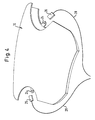
- Figure 4 shows a possibility of realizing the electrical Connection of the heating means 18 to a power supply (not shown).
- the connections 20 consist of the cover cap 10 incorporated flat plugs 24, which are plugged onto the sleeves 26 are in turn connected to a power supply via cable 28.
- FIG. 5a is an electrical conductive plastic layer 44 into the inside of the cap 10 poured.
- Elongated electrical contacts Metal contact strips 46 are provided, which are preferably in one piece with Flat plugs 24 are connected.
- the connection to a power source takes place as described in connection with Figure 4.
- the length of the Contact strip 46 corresponds approximately to the extent of the electrically conductive Layer 44 to ensure a uniform current flow through layer 44 guarantee.
- the current flow is illustrated by arrows in FIG. 5a.
- the contact strips 46 can also be on the angled edges 14 be arranged as long as they are in electrical contact with layer 44 are located.
- the contact strips 46 are preferably designed so that they during the injection molding process in the injection mold and by overmolding can be connected to the cap 10.
- the Cover cap so shaped that it e.g. has a recess into which the contact strips can be inserted or glued in a form-fitting manner.
- layer 44 may have an interruption, consistently trained or in their shape of the weakening zone be adjusted.
- Figure 5b shows alternative arrangement options for a total of four Contact strips 46.
- FIG. 7 shows an embodiment of an inventive Cover cap 10 with two arranged on the inside of the cover cap Heating mats 42.
- the heating mats 42 leave a weakening zone 22 free to not to interfere with the opening of the cover cap.
- There are 42 per heating mat two electrical connections are provided via flat plug 24, which like described are connected to a power source.
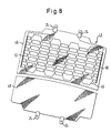
- the structure of the heating mats is shown in more detail in FIG.
- the Heating mats 42 consist of a fabric 48 onto which heating wires 40 are upset. Only the fabric 48 of the lower heating mat is shown, corresponding heating wires 40 are present, but not shown. This Heating wires 40 are connected to tabs 24 via contact strips 50.
- the heating mat 42 can be attached to the plastic layer 12 of the cap 10 e.g. be fixed by ultrasonic welding.
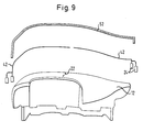
- FIG. 9 Another embodiment is shown in FIG. 9. This Embodiment is preferred to a leather covered cap with a To provide heating means 18.
- the body that forms the cap Plastic layer is connected on the outside to two heating mats 42, which leave a weakened zone 22.
- a leather cover 52 is placed over the Assembly of plastic layer 12 and heating mats 42 applied.
- thermocontrol electronics with an im Area of the heating means arranged temperature sensors may be provided are not shown here.
- the power supply of the heating means 18 can for the use of the cover cap on a driver gas bag to the supply of the other electrical consumers connected in the steering wheel or as independent electrical system can be implemented.
Landscapes
- Engineering & Computer Science (AREA)
- Mechanical Engineering (AREA)
- Air Bags (AREA)
Abstract
Description
- Fig. 1 eine schematische Schnittansicht einer erfindungsgemäßen Abdeckkappe gemäß einer ersten Ausführungsform;
- Fig. 2 eine schematische Schnittansicht einer erfindungsgemäßen Abdeckkappe gemäß einer zweiten Ausführungsform;
- Fig. 3 eine schematische Schnittansicht einer erfindungsgemäßen Abdeckkappe gemäß einer weiteren Ausführungsform;
- Figur 4 eine schematische dreidimensionale Ansicht einer erfindungsgemäßen Abdeckkappe;
- Figuren 5a und 5b eine schematische Ansicht der Innenseite einer erfindungsgemäßen, eine leitfähige Kunststoffschicht aufweisenden Abdeckkappe gemäß einer weiteren Ausführungsform, wobei Fig. 5b eine geringfügige Modifikation gegenüber der Ausführungsform nach Fig. 5a zeigt;
- Figuren 6a und 6b verschiedene, bei der erfindungsgemäßen Abdeckkappe einsetzbare Heizmittel;
- Figur 7 eine schematische Ansicht der Innenseite einer erfindungsgemäßen, eine Heizmatte aufweisenden Abdeckkappe gemäß einer weiteren Ausführungsform;
- Figur 8 eine Ansicht einer bei der erfindungsgemäßen Abdeckkappe einsetzbaren Heizmatte; und
- Figur 9 eine schematische Explosionsansicht einer erfindungsgemäßen Abdeckkappe mit einem Lederüberzug gemäß einer weiteren Ausführungsform.
Claims (10)
- Abdeckkappe für ein Gassackmodul einer Fahrzeuginsassen-Rückhaltevorrichtung, mit wenigstens einer Kunststoffschicht, dadurch gekennzeichnet, daß die Abdeckkappe (10) wenigstens stellenweise mit einem Heizmittel (18) versehen ist.
- Abdeckkappe nach Anspruch 1, dadurch gekennzeichnet, daß die Abdeckkappe (10) eine Schwächungszone (22) aufweist und daß das Heizmittel (18) im Bereich der Schwächungszone (22) angeordnet ist.
- Abdeckkappe nach Anspruch 1 oder 2, dadurch gekennzeichnet, daß das Heizmittel eine elektrische Heizung ist.
- Abdeckkappe nach Anspruch 3, dadurch gekennzeichnet, daß das Heizmittel (18) ein Heizdraht (40) ist.
- Abdeckkappe nach Anspruch 3, dadurch gekennzeichnet, daß das Heizmittel (18) aus einem elektrisch leitfähigen Kunststoff besteht.
- Abdeckkappe nach Anspruch 5, dadurch gekennzeichnet, daß in die Abdeckkappe (10) eine Schicht (44) aus elektrisch leitfähigem Kunststoff eingegossen ist.
- Abdeckkappe nach einem der vorhergehenden Ansprüche, dadurch gekennzeichnet, daß elektrische Verbindungselemente (20) zum Anschluß einer Stromquelle an das Heizmittel (18) vorgesehen sind, die in einer Kunststoffschicht der Abdeckkappe (10) eingegossen sind.
- Abdeckkappe nach Anspruch 3, dadurch gekennzeichnet, daß das Heizmittel (10) eine Heizmatte (42) ist.
- Abdeckkappe nach Anspruch 8, dadurch gekennzeichnet, daß die Heizmatte (42) mit einer Kunststoffschicht (12) der Abdeckkappe (10) ultraschallverschweißt ist.
- Abdeckkappe nach einem der vorhergehenden Ansprüche, dadurch gekennzeichnet, daß ein Lederüberzug (52) vorgesehen ist und daß das Heizmittel (18) zwischen einer Kunststoffschicht (12) der Abdeckkappe (10) und dem Lederüberzug (52) angeordnet ist.
Priority Applications (2)
| Application Number | Priority Date | Filing Date | Title |
|---|---|---|---|
| EP04004684A EP1433668A3 (de) | 2000-02-24 | 2001-01-29 | Gassackmodulabdeckkappe mit Heizmittel |
| EP04004685A EP1433669A3 (de) | 2000-02-24 | 2001-01-29 | Gassackmodulabdeckkappe mit Heizmittel |
Applications Claiming Priority (2)
| Application Number | Priority Date | Filing Date | Title |
|---|---|---|---|
| DE20003365U DE20003365U1 (de) | 2000-02-24 | 2000-02-24 | Abdeckkappe für ein Gassackmodul |
| DE20003365U | 2000-02-24 |
Related Child Applications (2)
| Application Number | Title | Priority Date | Filing Date |
|---|---|---|---|
| EP04004684A Division EP1433668A3 (de) | 2000-02-24 | 2001-01-29 | Gassackmodulabdeckkappe mit Heizmittel |
| EP04004685A Division EP1433669A3 (de) | 2000-02-24 | 2001-01-29 | Gassackmodulabdeckkappe mit Heizmittel |
Publications (2)
| Publication Number | Publication Date |
|---|---|
| EP1127754A1 true EP1127754A1 (de) | 2001-08-29 |
| EP1127754B1 EP1127754B1 (de) | 2004-10-06 |
Family
ID=7937831
Family Applications (3)
| Application Number | Title | Priority Date | Filing Date |
|---|---|---|---|
| EP04004685A Withdrawn EP1433669A3 (de) | 2000-02-24 | 2001-01-29 | Gassackmodulabdeckkappe mit Heizmittel |
| EP01101669A Expired - Lifetime EP1127754B1 (de) | 2000-02-24 | 2001-01-29 | Gassackmodulabdeckkappe mit Heizmittel |
| EP04004684A Withdrawn EP1433668A3 (de) | 2000-02-24 | 2001-01-29 | Gassackmodulabdeckkappe mit Heizmittel |
Family Applications Before (1)
| Application Number | Title | Priority Date | Filing Date |
|---|---|---|---|
| EP04004685A Withdrawn EP1433669A3 (de) | 2000-02-24 | 2001-01-29 | Gassackmodulabdeckkappe mit Heizmittel |
Family Applications After (1)
| Application Number | Title | Priority Date | Filing Date |
|---|---|---|---|
| EP04004684A Withdrawn EP1433668A3 (de) | 2000-02-24 | 2001-01-29 | Gassackmodulabdeckkappe mit Heizmittel |
Country Status (4)
| Country | Link |
|---|---|
| US (1) | US6454295B2 (de) |
| EP (3) | EP1433669A3 (de) |
| DE (2) | DE20003365U1 (de) |
| ES (1) | ES2230183T3 (de) |
Cited By (4)
| Publication number | Priority date | Publication date | Assignee | Title |
|---|---|---|---|---|
| DE10333617A1 (de) * | 2003-07-24 | 2005-03-03 | Autoliv Development Ab | Beheizbare Airbagvorrichtung für ein Fahrzeug |
| DE102008047690A1 (de) | 2008-09-18 | 2010-03-25 | GM Global Technology Operations, Inc., Detroit | Fahrzeuginnenverkleidung und Temperierungsverfahren |
| DE102014001339B3 (de) * | 2014-01-24 | 2015-05-21 | Autoliv Development Ab | Airbagvorrichtung für ein Fahrzeug |
| DE102016007451A1 (de) | 2016-06-17 | 2017-12-21 | Audi Ag | Airbagmodul und Lenkrad für ein Fahrzeug |
Families Citing this family (7)
| Publication number | Priority date | Publication date | Assignee | Title |
|---|---|---|---|---|
| DE10231131C5 (de) | 2002-07-10 | 2020-01-09 | Lisa Dräxlmaier GmbH | Armaturenbrett für ein Fahrzeug |
| US20090102168A1 (en) * | 2007-10-23 | 2009-04-23 | Hyun Kim | Door of passenger air bag for vehicle |
| DE102008056158B4 (de) | 2008-11-06 | 2011-05-05 | D'Onorio De Meo, Marco, Dr. | Verfahren zur Steuerung und Installation eines audiovisuellen Kommunikationsgerätes mit einfacher Handhabung, eine besondere Kamerasteuerungseinrichtung und Verwendung für die Unterstützung einer Person |
| DE202011004899U1 (de) * | 2011-04-05 | 2012-07-09 | Peguform Gmbh | Kraftfahrzeuginnenverkleidungsbauteil aus Kunststoff |
| DE102011007432A1 (de) * | 2011-04-14 | 2012-10-18 | Behr Gmbh & Co. Kg | Bauteil und zugehöriges Herstellungsverfahren |
| EP3971028A1 (de) * | 2020-09-18 | 2022-03-23 | Autoneum Management AG | Kraftfahrzeugverkleidungsteil mit integrierter heizvorrichtung |
| DE102022207667B4 (de) * | 2022-07-27 | 2024-07-11 | Zf Friedrichshafen Ag | Vorheizen eines Temperaturelements eines Sicherheitssystems |
Citations (5)
| Publication number | Priority date | Publication date | Assignee | Title |
|---|---|---|---|---|
| EP0681944A1 (de) * | 1994-05-11 | 1995-11-15 | Morton International, Inc. | Airbag-Hupenschalter mit Temperaturkompensation |
| JPH1076544A (ja) * | 1996-09-03 | 1998-03-24 | Kansei Corp | 車両用内装パネル及びその成形方法 |
| US5804121A (en) * | 1995-04-21 | 1998-09-08 | Davidson Textron Inc. | Method of forming a motor vehicle instrument panel with a flexibly tethered air bag deployment door |
| US5902428A (en) * | 1995-03-31 | 1999-05-11 | Davidson Textron Inc. | Motor vehicle instrument panel with flexible tethering hinged air bag deployment door |
| DE19907742A1 (de) * | 1999-02-23 | 2000-08-24 | Volkswagen Ag | Insassenschutzvorrichtung mit einem Airbag für ein Kraftfahrzeug |
Family Cites Families (14)
| Publication number | Priority date | Publication date | Assignee | Title |
|---|---|---|---|---|
| US4310174A (en) * | 1978-04-07 | 1982-01-12 | General Motors Corporation | Steering column electrical connector arrangement |
| ES2050681T5 (es) | 1988-08-05 | 1997-11-16 | Karlheinz Beckhausen | Carril de contacto de seguridad. |
| US5797619A (en) * | 1989-01-30 | 1998-08-25 | Tip Engineering Group, Inc. | Automotive trim piece and method to form an air bag opening |
| US5611564A (en) * | 1993-08-18 | 1997-03-18 | Tip Engineering Group, Inc. | Method and treatment for forming an air bag deployment opening in leather covered trim |
| US5335935A (en) * | 1992-08-31 | 1994-08-09 | Plastic Mold Technology Incorporated | Air bag cover/molded article with integral cover layer of leather |
| US5296658A (en) | 1992-09-25 | 1994-03-22 | Rockwell International Corporation | Safety edge switch for detection of obstructions encountered by a moving object |
| US5390950A (en) | 1993-03-04 | 1995-02-21 | Tip Eng Group Inc | Method and arrangement for forming an air bag deployment opening in an auto interior trim piece |
| US5372379A (en) | 1994-02-15 | 1994-12-13 | Davidson Textron Inc. | Preheated safety air bag cover |
| GB9519847D0 (en) * | 1995-09-29 | 1995-11-29 | United Technologies Automotive | Crash protection device |
| US5961869A (en) * | 1995-11-13 | 1999-10-05 | Irgens; O. Stephan | Electrically insulated adhesive-coated heating element |
| JPH09183374A (ja) * | 1995-12-28 | 1997-07-15 | Tokyo Seat Kk | 皮革貼りエアバッグカバー |
| JPH09183372A (ja) * | 1995-12-28 | 1997-07-15 | Tokyo Seat Kk | 皮革貼りエアバッグカバー |
| JPH09183373A (ja) * | 1995-12-28 | 1997-07-15 | Tokyo Seat Kk | 皮革貼りエアバッグカバー |
| DE19653797A1 (de) * | 1996-12-21 | 1998-06-25 | Mst Automotive Gmbh | Abdeckung für ein Airbag-Modul |
-
2000
- 2000-02-24 DE DE20003365U patent/DE20003365U1/de not_active Expired - Lifetime
-
2001
- 2001-01-29 ES ES01101669T patent/ES2230183T3/es not_active Expired - Lifetime
- 2001-01-29 EP EP04004685A patent/EP1433669A3/de not_active Withdrawn
- 2001-01-29 DE DE50103931T patent/DE50103931D1/de not_active Expired - Fee Related
- 2001-01-29 EP EP01101669A patent/EP1127754B1/de not_active Expired - Lifetime
- 2001-01-29 EP EP04004684A patent/EP1433668A3/de not_active Withdrawn
- 2001-01-30 US US09/772,837 patent/US6454295B2/en not_active Expired - Fee Related
Patent Citations (5)
| Publication number | Priority date | Publication date | Assignee | Title |
|---|---|---|---|---|
| EP0681944A1 (de) * | 1994-05-11 | 1995-11-15 | Morton International, Inc. | Airbag-Hupenschalter mit Temperaturkompensation |
| US5902428A (en) * | 1995-03-31 | 1999-05-11 | Davidson Textron Inc. | Motor vehicle instrument panel with flexible tethering hinged air bag deployment door |
| US5804121A (en) * | 1995-04-21 | 1998-09-08 | Davidson Textron Inc. | Method of forming a motor vehicle instrument panel with a flexibly tethered air bag deployment door |
| JPH1076544A (ja) * | 1996-09-03 | 1998-03-24 | Kansei Corp | 車両用内装パネル及びその成形方法 |
| DE19907742A1 (de) * | 1999-02-23 | 2000-08-24 | Volkswagen Ag | Insassenschutzvorrichtung mit einem Airbag für ein Kraftfahrzeug |
Non-Patent Citations (1)
| Title |
|---|
| PATENT ABSTRACTS OF JAPAN vol. 1998, no. 08 30 June 1998 (1998-06-30) * |
Cited By (5)
| Publication number | Priority date | Publication date | Assignee | Title |
|---|---|---|---|---|
| DE10333617A1 (de) * | 2003-07-24 | 2005-03-03 | Autoliv Development Ab | Beheizbare Airbagvorrichtung für ein Fahrzeug |
| DE10333617B4 (de) * | 2003-07-24 | 2005-07-28 | Autoliv Development Ab | Beheizbare Airbagvorrichtung für ein Fahrzeug |
| DE102008047690A1 (de) | 2008-09-18 | 2010-03-25 | GM Global Technology Operations, Inc., Detroit | Fahrzeuginnenverkleidung und Temperierungsverfahren |
| DE102014001339B3 (de) * | 2014-01-24 | 2015-05-21 | Autoliv Development Ab | Airbagvorrichtung für ein Fahrzeug |
| DE102016007451A1 (de) | 2016-06-17 | 2017-12-21 | Audi Ag | Airbagmodul und Lenkrad für ein Fahrzeug |
Also Published As
| Publication number | Publication date |
|---|---|
| EP1433668A2 (de) | 2004-06-30 |
| EP1433669A3 (de) | 2005-11-16 |
| US6454295B2 (en) | 2002-09-24 |
| EP1127754B1 (de) | 2004-10-06 |
| DE50103931D1 (de) | 2004-11-11 |
| EP1433669A2 (de) | 2004-06-30 |
| ES2230183T3 (es) | 2005-05-01 |
| DE20003365U1 (de) | 2000-08-10 |
| EP1433668A3 (de) | 2005-11-16 |
| US20010017457A1 (en) | 2001-08-30 |
Similar Documents
| Publication | Publication Date | Title |
|---|---|---|
| EP1181172B1 (de) | Lenkrad | |
| EP0608554B1 (de) | Anschlusselement für eine Glasscheibe mit elektrischer Anordnung | |
| DE19750103B4 (de) | Flachkabel-Verbindungsanordnung | |
| EP2165580B1 (de) | Schliesssystem für fahrzeuge und verwendung eines komponententrägers | |
| EP1127754B1 (de) | Gassackmodulabdeckkappe mit Heizmittel | |
| EP1283005A1 (de) | Kombiniertes sensor- und heizelement | |
| EP0904613B1 (de) | Steckverbinder mit einer mit elektrischen bauelementen bestückten leiterbahnstruktur sowie verfahren zur herstellung eines solchen | |
| EP4110579B1 (de) | Beheizbares kunststoffbauteil und verfahren zu dessen herstellung | |
| DE69325378T2 (de) | Elektrischer regensensor und verfahren zum herstellen eines sensorbauteils | |
| WO2014124995A1 (de) | Vereinfachte kapazitive sensoreinheit | |
| EP3619781B1 (de) | Elektro-bauteil und verfahren zu dessen herstellung | |
| EP2947773A1 (de) | Variabel einsetzbare sensoreinheit | |
| WO2018146061A1 (de) | Lenkrad und verfahren zur herstellung eines lenkrads | |
| EP0980322B1 (de) | Sensorschaltung für kraftfahrzeuge | |
| EP1040311B1 (de) | Integrierte schaltungsanordnung zum aufheizen von zündmaterial sowie verwendung einer solchen integrierten schaltungsanordnung | |
| DE3519303C2 (de) | Gleichspannungsgespeister Näherungsschalter | |
| EP3640655A1 (de) | Batteriesensor und verfahren zur herstellung eines batteriesensors | |
| DE602005003827T2 (de) | Innenmaterialstruktur für fahrzeug | |
| EP1083627B1 (de) | Elektrische Verbinderbaugruppe mit Flachkabel | |
| DE29813239U1 (de) | Kontaktvorrichtung | |
| DE19732851C2 (de) | Elektrische Anschlußvorrichtung | |
| DE10260271B4 (de) | Vorrichtung zum Auslösen einer elektrischen Sicherung in einem Versorgungsstromkreis | |
| EP1351560A2 (de) | Verfahren zur Herstellung eines elektronischen Geräts und elektronisches Gerät | |
| DE19708306A1 (de) | Kraftfahrzeug-Diebstahlsicherung | |
| DE10063367A1 (de) | Elektrisches Kraftfahrzeugschloß-Modul und Verfahren zu seiner Herstellung |
Legal Events
| Date | Code | Title | Description |
|---|---|---|---|
| PUAI | Public reference made under article 153(3) epc to a published international application that has entered the european phase |
Free format text: ORIGINAL CODE: 0009012 |
|
| AK | Designated contracting states |
Kind code of ref document: A1 Designated state(s): AT BE CH CY DE DK ES FI FR GB GR IE IT LI LU MC NL PT SE TR |
|
| AX | Request for extension of the european patent |
Free format text: AL;LT;LV;MK;RO;SI |
|
| 17P | Request for examination filed |
Effective date: 20020107 |
|
| AKX | Designation fees paid |
Free format text: DE ES FR GB IT |
|
| 17Q | First examination report despatched |
Effective date: 20030819 |
|
| GRAP | Despatch of communication of intention to grant a patent |
Free format text: ORIGINAL CODE: EPIDOSNIGR1 |
|
| RAP1 | Party data changed (applicant data changed or rights of an application transferred) |
Owner name: TRW AUTOMOTIVE SAFETY SYSTEMS GMBH |
|
| GRAS | Grant fee paid |
Free format text: ORIGINAL CODE: EPIDOSNIGR3 |
|
| GRAA | (expected) grant |
Free format text: ORIGINAL CODE: 0009210 |
|
| AK | Designated contracting states |
Kind code of ref document: B1 Designated state(s): DE ES FR GB IT |
|
| REG | Reference to a national code |
Ref country code: GB Ref legal event code: FG4D Free format text: NOT ENGLISH |
|
| REF | Corresponds to: |
Ref document number: 50103931 Country of ref document: DE Date of ref document: 20041111 Kind code of ref document: P |
|
| PGFP | Annual fee paid to national office [announced via postgrant information from national office to epo] |
Ref country code: GB Payment date: 20041210 Year of fee payment: 5 |
|
| PGFP | Annual fee paid to national office [announced via postgrant information from national office to epo] |
Ref country code: FR Payment date: 20050105 Year of fee payment: 5 |
|
| PGFP | Annual fee paid to national office [announced via postgrant information from national office to epo] |
Ref country code: ES Payment date: 20050120 Year of fee payment: 5 |
|
| PGFP | Annual fee paid to national office [announced via postgrant information from national office to epo] |
Ref country code: DE Payment date: 20050131 Year of fee payment: 5 |
|
| REG | Reference to a national code |
Ref country code: ES Ref legal event code: FG2A Ref document number: 2230183 Country of ref document: ES Kind code of ref document: T3 |
|
| PLBE | No opposition filed within time limit |
Free format text: ORIGINAL CODE: 0009261 |
|
| STAA | Information on the status of an ep patent application or granted ep patent |
Free format text: STATUS: NO OPPOSITION FILED WITHIN TIME LIMIT |
|
| ET | Fr: translation filed | ||
| 26N | No opposition filed |
Effective date: 20050707 |
|
| PG25 | Lapsed in a contracting state [announced via postgrant information from national office to epo] |
Ref country code: GB Free format text: LAPSE BECAUSE OF NON-PAYMENT OF DUE FEES Effective date: 20060129 |
|
| PG25 | Lapsed in a contracting state [announced via postgrant information from national office to epo] |
Ref country code: ES Free format text: LAPSE BECAUSE OF NON-PAYMENT OF DUE FEES Effective date: 20060130 |
|
| PG25 | Lapsed in a contracting state [announced via postgrant information from national office to epo] |
Ref country code: FR Free format text: LAPSE BECAUSE OF NON-PAYMENT OF DUE FEES Effective date: 20060131 |
|
| PGFP | Annual fee paid to national office [announced via postgrant information from national office to epo] |
Ref country code: IT Payment date: 20060131 Year of fee payment: 6 |
|
| PG25 | Lapsed in a contracting state [announced via postgrant information from national office to epo] |
Ref country code: DE Free format text: LAPSE BECAUSE OF NON-PAYMENT OF DUE FEES Effective date: 20060801 |
|
| GBPC | Gb: european patent ceased through non-payment of renewal fee |
Effective date: 20060129 |
|
| REG | Reference to a national code |
Ref country code: FR Ref legal event code: ST Effective date: 20060929 |
|
| REG | Reference to a national code |
Ref country code: ES Ref legal event code: FD2A Effective date: 20060130 |
|
| PG25 | Lapsed in a contracting state [announced via postgrant information from national office to epo] |
Ref country code: IT Free format text: LAPSE BECAUSE OF NON-PAYMENT OF DUE FEES Effective date: 20070129 |