EP1127663A1 - Dispositif de préhension - Google Patents
Dispositif de préhension Download PDFInfo
- Publication number
- EP1127663A1 EP1127663A1 EP00610011A EP00610011A EP1127663A1 EP 1127663 A1 EP1127663 A1 EP 1127663A1 EP 00610011 A EP00610011 A EP 00610011A EP 00610011 A EP00610011 A EP 00610011A EP 1127663 A1 EP1127663 A1 EP 1127663A1
- Authority
- EP
- European Patent Office
- Prior art keywords
- gripping device
- finger
- fingers
- slide
- finger portion
- Prior art date
- Legal status (The legal status is an assumption and is not a legal conclusion. Google has not performed a legal analysis and makes no representation as to the accuracy of the status listed.)
- Withdrawn
Links
Images
Classifications
-
- B—PERFORMING OPERATIONS; TRANSPORTING
- B25—HAND TOOLS; PORTABLE POWER-DRIVEN TOOLS; MANIPULATORS
- B25J—MANIPULATORS; CHAMBERS PROVIDED WITH MANIPULATION DEVICES
- B25J15/00—Gripping heads and other end effectors
- B25J15/08—Gripping heads and other end effectors having finger members
- B25J15/12—Gripping heads and other end effectors having finger members with flexible finger members
-
- H—ELECTRICITY
- H05—ELECTRIC TECHNIQUES NOT OTHERWISE PROVIDED FOR
- H05K—PRINTED CIRCUITS; CASINGS OR CONSTRUCTIONAL DETAILS OF ELECTRIC APPARATUS; MANUFACTURE OF ASSEMBLAGES OF ELECTRICAL COMPONENTS
- H05K13/00—Apparatus or processes specially adapted for manufacturing or adjusting assemblages of electric components
- H05K13/04—Mounting of components, e.g. of leadless components
- H05K13/0404—Pick-and-place heads or apparatus, e.g. with jaws
- H05K13/0408—Incorporating a pick-up tool
Definitions
- the invention relates to a gripping device for a component mounting machine, said gripping device comprising a gripping device body with a finger portion, said finger portion being provided with at least two elongate fingers made in one piece, each finger having an outer edge, said outer edges being provided for, in cooperation, gripping a component, said at least two fingers being flexible in relation to each other so that the outer edges of the fingers are movable towards and away from each other.
- NO-B-167 366 shows a gripping device of this type in which two gripping fingers made in one piece extend parallel with each other. One of the fingers has a portion with two thin, parallel walls thereby making it elastically deformable. When a lateral pressure is applied directly on the finger, it is moved towards the other finger.
- DE-Al-196 44 502 shows a gripping device comprising fingers which are made integrally with the body of the gripper. Each finger is connected to the body of the gripping device via a narrow bridge forming a relatively rigid hinge. The inner end of each finger is provided with a lever and a disc is arranged for pressing the levers thereby causing the fingers to tilt about their relatively rigid hinges.
- US-A-5 458 388 shows a gripping device comprising a vacuum chamber provided with a piston that is retracted when a vacuum is applied.
- the piston presses on levers connected to gripping fingers which are moved towards each other by tilting about hinge portions of the fingers.
- the above-mentioned devices are characterised in that the gripping fingers are made in one piece and that a force is applied for forcing the fingers towards each other.
- the fingers are deformed elastically and the inherent elasticity of the finger material causes the fingers to be moved away from each other once the applied force is removed again.
- the known gripping devices may be accurate in their gripping action, but when the components are to be released by removal of the applied force that forces the fingers towards each other, the movement of the fingers are totally dependent on the inherent elasticity of the finger material. This may - especially over time - cause inaccurate and unforseeable positions of the fingers which is most undesirable in precision machine works.
- the object of the invention is to provide a gripper that overcomes this problem.
- positive movement when used in this specification is meant to mean movement in either direction directly and unambiguously controlled by a positive engagement between the slide and the finger portion.
- the finger portion is made in one piece with the gripping device body thereby reducing the number of separate parts in the gripping device. This facilitates assembling of the gripping device and furthermore eliminates any play and requirements to manufacturing tolerances between the otherwise two parts.
- the slide is provided with a notch that cooperates with a guiding knob provided on the finger portion.
- the guiding knob is displaced accordingly causing the fingers of the finger portion to be displaced towards or away from each other.
- the finger portion is provided with two fingers, one of said fingers being in substantially rigid relation to the gripping device body, the other being flexible in relation to the gripping device body.
- the flexibility may be achieved by providing a narrow tongue interconnecting the two fingers, and in a preferred embodiment the tongue extends substantially parallel with a longitudinal direction of the fingers and is connected to one finger at a first end thereof and to the other finger at a second end thereof.
- This structure results in a slim design of the finger portion, while maintaining its high flexibility. It is therefore especially suitable for mounting of small components even in narrow places.
- a pneumatic actuator may be provided for displacing the slide in relation to the gripping device body thereby making it suitable for any kind of mounting machine where compressed air is available.
- other types of actuators may be applied, e.g. electric motors.
- a guideway may be provided in the slide, said guideway being able to cooperate with a guiding pin provided on the gripping device body.
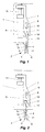
- the gripping device according to the invention shown in Fig. 1 and 2 comprises a gripping device body 1 with a finger portion 2 provided with two fingers 3, 4 each having an outer edge 5, 6, a slide 7 having a guideway 8 and a pneumatic actuator 9.
- the gripping device is mountable in a component mounting machine, such as a robot mounting cell or the like.
- the gripping device is shown in its closed position in Fig. 1, i.e. the gap between the outer edges 5, 6 is as small as possible. This gap is shaped in accordance with the component that is to be handled by the gripping device.
- the finger portion 2 comprises two slots 10, 11, a bridging portion 12 and an elongated finger part 13 having a guiding knop 14 at its upper end.
- the finger portion 2 is made of the same piece as the gripping device body 1, hence they are in rigid relation via the bridging portion 12. The rest of the finger portion 2 is positioned in front of the gripping device body 1.
- the finger portion 2 may be made as a separate part that is fastened to the gripping device body 1, e.g. by bolts extending through a backwards extending part of the bridging portion 12.
- the two slots 10, 11 give the finger portion 2 some flexibility allowing the outer edges 5, 6 of the fingers 3, 4 to be moved towards and away from each other in order to grip and release a component.
- the movement of the fingers 3, 4 is preferably such that only elastic deformation of the finger portion 2 occurs.
- a slide 7 cooperating with the guiding knob 14 of the finger portion 2 is positioned on the front of the gripping device body 1.
- the slide 7 is movable in the vertical direction via the pneumatic actuator 9, the housing of which is firmly connected to the gripping device body 1 and the piston 15 being connected to the upper end of the slide 7.
- the movement is determined by the vertical movement of the piston 15 and the cooperation of the guideway 8 provided in the slide 7 with a guiding pin 16 connected to the gripper device body 1.
- the lower end of the slide 7 is provided with a notch 17 that cooperates with the guiding knob 14 of the finger portion 2.
- the notch 17 is provided with inclined side faces which force the guiding knob 14 to move laterally when the slide 7 is displaced vertically.
- the lateral displacement of the guiding knob 14 causes the outer edge 6 of the finger 4 to be laterally displaced as well, thereby opening or closing the gap between the outer edges 5, 6 of the fingers 3, 4.
- the play between the side faces of the notch 17 and the guiding knop 14 of the finger portion 2 is reduced to a minimum in order to ensure that the position of the guiding knob 14 - and thereby the outer edge 6 of the finger 4 - is detemineable at all times dependent only of the position of the slide 7.
- Fig. 2 the slide 7 has been displaced downwards by means of the pneumatic actuator 9. Due to the shape of the notch 17 and the interaction between the notch 17 and the guiding knop 14, the latter is forced to the left as shown. Since the finger portion 2 is flexible, the outer edge 6 of the finger 4 is displaced to the right as shown, thereby opening the gap between the outer edges 5, 6 of the fingers 3, 4. In this position the gripper device is ready for gripping a component.
- the pneumatic actuator 9 When a component has been positioned between the outer edges 5, 6 of the fingers 3, 4, the pneumatic actuator 9 is activated and causes the slide 7 to be displaced upwards. This forces the guiding knob 14 to the right which in turn closes the gap between the outer edges 5, 6 of the fingers 3, 4 thereby gripping the component.
- the slide 7 is displaced downwards again which opens the gap between the outer edges 5, 6 of the fingers 3, 4 and thereby releases the component.
- the gripper device is then ready for gripping another component.
- the slide could be horisontally displaceable instead of vertically displaceable if it is required to limit the height of the gripper device, e.g. due to limited free space above the gripper device.
- the flexibility of the finger portion could also be achieved by shaping the elastical part differently. It is, however, important that the finger portion is made in one piece thereby avoiding the high requirements to acceptable manufacturing tolerances that would have been necessary had the finger portion consisted of more pieces.
Landscapes
- Engineering & Computer Science (AREA)
- Robotics (AREA)
- Mechanical Engineering (AREA)
- Manufacturing & Machinery (AREA)
- Microelectronics & Electronic Packaging (AREA)
- Manipulator (AREA)
Priority Applications (4)
| Application Number | Priority Date | Filing Date | Title |
|---|---|---|---|
| EP00610011A EP1127663A1 (fr) | 2000-01-26 | 2000-01-26 | Dispositif de préhension |
| PCT/EP2000/012928 WO2001054868A1 (fr) | 2000-01-26 | 2000-12-18 | Dispositif de prehension |
| AU21682/01A AU2168201A (en) | 2000-01-26 | 2000-12-18 | Gripping device |
| US09/769,722 US6481770B2 (en) | 2000-01-26 | 2001-01-25 | Gripping device |
Applications Claiming Priority (1)
| Application Number | Priority Date | Filing Date | Title |
|---|---|---|---|
| EP00610011A EP1127663A1 (fr) | 2000-01-26 | 2000-01-26 | Dispositif de préhension |
Publications (1)
| Publication Number | Publication Date |
|---|---|
| EP1127663A1 true EP1127663A1 (fr) | 2001-08-29 |
Family
ID=8174364
Family Applications (1)
| Application Number | Title | Priority Date | Filing Date |
|---|---|---|---|
| EP00610011A Withdrawn EP1127663A1 (fr) | 2000-01-26 | 2000-01-26 | Dispositif de préhension |
Country Status (4)
| Country | Link |
|---|---|
| US (1) | US6481770B2 (fr) |
| EP (1) | EP1127663A1 (fr) |
| AU (1) | AU2168201A (fr) |
| WO (1) | WO2001054868A1 (fr) |
Families Citing this family (6)
| Publication number | Priority date | Publication date | Assignee | Title |
|---|---|---|---|---|
| US20040005213A1 (en) * | 2002-05-22 | 2004-01-08 | Pavel Hegedus | Method and apparatus for firm handling disc shaped objects with a concentric bore |
| ITTO20060518A1 (it) * | 2006-07-14 | 2008-01-15 | Alenia Aeronautica Spa | Metodo, attrezzatura e impianto per la lavorazione di strutture a guscio |
| JP4871910B2 (ja) * | 2007-05-16 | 2012-02-08 | 株式会社日立ハイテクノロジーズ | ディスクチャック機構およびディスクハンドリングロボット |
| TWI808983B (zh) * | 2017-09-08 | 2023-07-21 | 日商索尼股份有限公司 | 機器人手部、機器人裝置及電子機器的製造方法 |
| WO2019077671A1 (fr) * | 2017-10-17 | 2019-04-25 | 株式会社Fuji | Tête de montage et machine de montage d'élément constitutif |
| CN212825430U (zh) * | 2020-05-07 | 2021-03-30 | 深圳蓝胖子机器智能有限公司 | 一种手指可拆卸的灵巧手 |
Citations (4)
| Publication number | Priority date | Publication date | Assignee | Title |
|---|---|---|---|---|
| US4045870A (en) * | 1977-01-28 | 1977-09-06 | Precision Engineered Products, Inc. | Socket inserter |
| US4179803A (en) * | 1976-10-21 | 1979-12-25 | Wolkert Per O M | Device for handling electrical components |
| DE19637618A1 (de) * | 1996-09-16 | 1998-03-19 | Staiger Steuerungstech | Pinzette |
| US5895084A (en) * | 1997-02-19 | 1999-04-20 | Mauro; George | Cam operated microgripper |
Family Cites Families (15)
| Publication number | Priority date | Publication date | Assignee | Title |
|---|---|---|---|---|
| US2899232A (en) * | 1959-08-11 | Bottle chuck | ||
| US2215844A (en) * | 1939-02-14 | 1940-09-24 | Cecil E Van Syckle | Material handling device |
| US3108835A (en) * | 1962-03-29 | 1963-10-29 | Lodge & Shipley Co | Externally gripping article transferring apparatus |
| GB1200141A (en) * | 1968-05-28 | 1970-07-29 | English Electric Co Ltd | Grabs |
| US3630391A (en) * | 1969-01-28 | 1971-12-28 | Gulf & Western Ind Prod Co | Work gripper |
| US3625378A (en) * | 1970-06-25 | 1971-12-07 | Frank H Attiz | High-vacuum manipulating tool |
| US4257639A (en) * | 1979-12-17 | 1981-03-24 | Rockwell International Corporation | Ejector device for stores |
| DE3011837A1 (de) * | 1980-03-27 | 1981-10-01 | Sommer, Friedhelm, 7530 Pforzheim | Handhabungsgreifer, bspw. fuer industrieroboter |
| US5938258A (en) * | 1986-02-15 | 1999-08-17 | Master Appliance Corp. | Power actuated tweezer |
| SU1572808A1 (ru) * | 1988-08-01 | 1990-06-23 | Предприятие П/Я Р-6409 | Схват промышленного робота |
| FR2679480B1 (fr) * | 1991-07-26 | 1993-10-15 | Roudaut Philippe | Pince pneumatique. |
| DK0532774T3 (da) * | 1991-09-16 | 1996-03-18 | Sig Schweiz Industrieges | Griber til en manipulator |
| NL9101846A (nl) * | 1991-11-05 | 1993-06-01 | Jong Dirk De | Compactdiskpakker. |
| US5458388A (en) | 1994-08-03 | 1995-10-17 | Universal Instruments Incorporated | Replaceable nozzle tip with vacuum actuated mechanical gripping fingers |
| DE19644502C2 (de) | 1996-10-25 | 2002-04-25 | Fraunhofer Ges Forschung | Greifervorrichtung für die Mikromontage kleiner Werkstücke mit wenigstens zwei Greiferelementen |
-
2000
- 2000-01-26 EP EP00610011A patent/EP1127663A1/fr not_active Withdrawn
- 2000-12-18 WO PCT/EP2000/012928 patent/WO2001054868A1/fr active Application Filing
- 2000-12-18 AU AU21682/01A patent/AU2168201A/en not_active Abandoned
-
2001
- 2001-01-25 US US09/769,722 patent/US6481770B2/en not_active Expired - Fee Related
Patent Citations (4)
| Publication number | Priority date | Publication date | Assignee | Title |
|---|---|---|---|---|
| US4179803A (en) * | 1976-10-21 | 1979-12-25 | Wolkert Per O M | Device for handling electrical components |
| US4045870A (en) * | 1977-01-28 | 1977-09-06 | Precision Engineered Products, Inc. | Socket inserter |
| DE19637618A1 (de) * | 1996-09-16 | 1998-03-19 | Staiger Steuerungstech | Pinzette |
| US5895084A (en) * | 1997-02-19 | 1999-04-20 | Mauro; George | Cam operated microgripper |
Also Published As
| Publication number | Publication date |
|---|---|
| AU2168201A (en) | 2001-08-07 |
| WO2001054868A1 (fr) | 2001-08-02 |
| US6481770B2 (en) | 2002-11-19 |
| US20010040381A1 (en) | 2001-11-15 |
Similar Documents
| Publication | Publication Date | Title |
|---|---|---|
| CA1181790A (fr) | Mecanisme de commutation a pedale | |
| DE10114551C1 (de) | Mikrogreifer | |
| US6667879B2 (en) | System for latching and ejecting a modular component from an electronic device | |
| US5115108A (en) | Two-stage rubber switch | |
| US6481770B2 (en) | Gripping device | |
| CN1127786C (zh) | 卡连接件中的推出机构 | |
| EP1202311A3 (fr) | Interrupteur à coulisse | |
| WO2004004976A2 (fr) | Serre-joint à barre avec levier de freinage activé latéralement | |
| CA3015506A1 (fr) | Appareil de suture chirurgicale | |
| US7750260B2 (en) | Leading auxiliary switch for circuit breaker | |
| ITTO980408A1 (it) | Serraggio di sicurezza | |
| US8177543B2 (en) | Demolding device for demolding a tool from a mold | |
| US6362441B1 (en) | Pneumatic foot switch assembly | |
| EP1528583A1 (fr) | Bouton poussoir | |
| JP3745667B2 (ja) | Icソケット | |
| WO2020067001A1 (fr) | Commutateur d'activation | |
| CN208903908U (zh) | 一种开关元件的触头系统 | |
| JP7174585B2 (ja) | イネーブルスイッチ | |
| JP3945207B2 (ja) | 射出成形装置 | |
| US5265786A (en) | Apparatus for placing surgical staples | |
| CN213532249U (zh) | 一种夹持装置 | |
| CN211138007U (zh) | 塑胶盖的同步取件装置 | |
| EP0780863B1 (fr) | Dispositif pour l'établissement d'une connexion électrique | |
| JP7223634B2 (ja) | グリップコネクタ把持用取付部材、及びそれを用いたグリップコネクタ把持装置 | |
| CN112890472B (zh) | 滑轨总成 |
Legal Events
| Date | Code | Title | Description |
|---|---|---|---|
| PUAI | Public reference made under article 153(3) epc to a published international application that has entered the european phase |
Free format text: ORIGINAL CODE: 0009012 |
|
| AK | Designated contracting states |
Kind code of ref document: A1 Designated state(s): AT BE CH CY DE DK ES FI FR GB GR IE IT LI LU MC NL PT SE |
|
| AX | Request for extension of the european patent |
Free format text: AL PAYMENT 20000202;LT PAYMENT 20000202;LV PAYMENT 20000202;MK PAYMENT 20000202;RO PAYMENT 20000202;SI PAYMENT 20000202 |
|
| 17P | Request for examination filed |
Effective date: 20020117 |
|
| AKX | Designation fees paid |
Free format text: AT BE CH CY DE DK ES FI FR GB GR IE IT LI LU MC NL PT SE |
|
| AXX | Extension fees paid |
Free format text: AL PAYMENT 20000202;LT PAYMENT 20000202;LV PAYMENT 20000202;MK PAYMENT 20000202;RO PAYMENT 20000202;SI PAYMENT 20000202 |
|
| 17Q | First examination report despatched |
Effective date: 20021030 |
|
| STAA | Information on the status of an ep patent application or granted ep patent |
Free format text: STATUS: THE APPLICATION IS DEEMED TO BE WITHDRAWN |
|
| RAP1 | Party data changed (applicant data changed or rights of an application transferred) |
Owner name: TELEFONAKTIEBOLAGET LM ERICSSON (PUBL) |
|
| 18D | Application deemed to be withdrawn |
Effective date: 20031121 |